1999 NISSAN PRIMERA Control
[x] Cancel search: ControlPage 664 of 2267
On Board Diagnosis LogicNCEC0202When a misfire occurs, the engine speed will fluctuate. If the engine speed fluctuates enough to cause the
CKP sensor signal to vary, The ECM can determine that a misfire is occurring.
Sensor Input Signal to ECM ECM function
Crankshaft position sensor (POS) Engine speed On board diagnosis of misfire
The misfire detection logic consists of the following two conditions.
1. One Trip Detection Logic (Three Way Catalyst Damage)
On the first trip that a misfire condition occurs that can damage the three way catalyst (TWC) due to
overheating, the MI will blink.
When a misfire condition occurs, the ECM monitors the CKP sensor signal every 200 engine revolutions
for a change.
When the misfire condition decreases to a level that will not damage the TWC, the MI will turn off.
If another misfire condition occurs that can damage the TWC on a second trip, the MI will blink.
When the misfire condition decreases to a level that will not damage the TWC, the MI will remain on.
If another misfire condition occurs that can damage the TWC, the MI will begin to blink again.
(After the first trip detection, the MI will light up from engine starting. If a misfire is detected that will cause
three way catalyst damage, the MI will start blinking.)
2. Two Trip Detection Logic (Exhaust quality deterioration)
For misfire conditions that will not damage the TWC (but will affect emissions), the MI will only light when
the misfire is detected on a second trip. During this condition, the ECM monitors the CKP sensor signal
every 1,000 engine revolutions.
A misfire malfunction can be detected on any one cylinder or on multiple cylinders.
DTC No. Malfunction is detected when ... Check Items (Possible Cause)
P0300
0300IMultiple cylinders misfire.IImproper spark plug
IInsufficient compression
IIncorrect fuel pressure
IEGR volume control valve (If so equipped)
IThe injector circuit is open or shorted
IInjectors
IIntake air leak
IInsufficient ignition spark
ILack of fuel
IHeated oxygen sensor 1 (front) P0301
0301INo. 1 cylinder misfires.
P0302
0302INo. 2 cylinder misfires.
P0303
0303INo. 3 cylinder misfires.
P0304
0304INo. 4 cylinder misfires.
DTC Confirmation ProcedureNCEC0203CAUTION:
Always drive vehicle at a safe speed.
NOTE:
If ªDTC Confirmation Procedureº has been previously conducted,
always turn ignition switch ªOFFº and wait at least 9 seconds
before conducting the next test.
With CONSULT-II
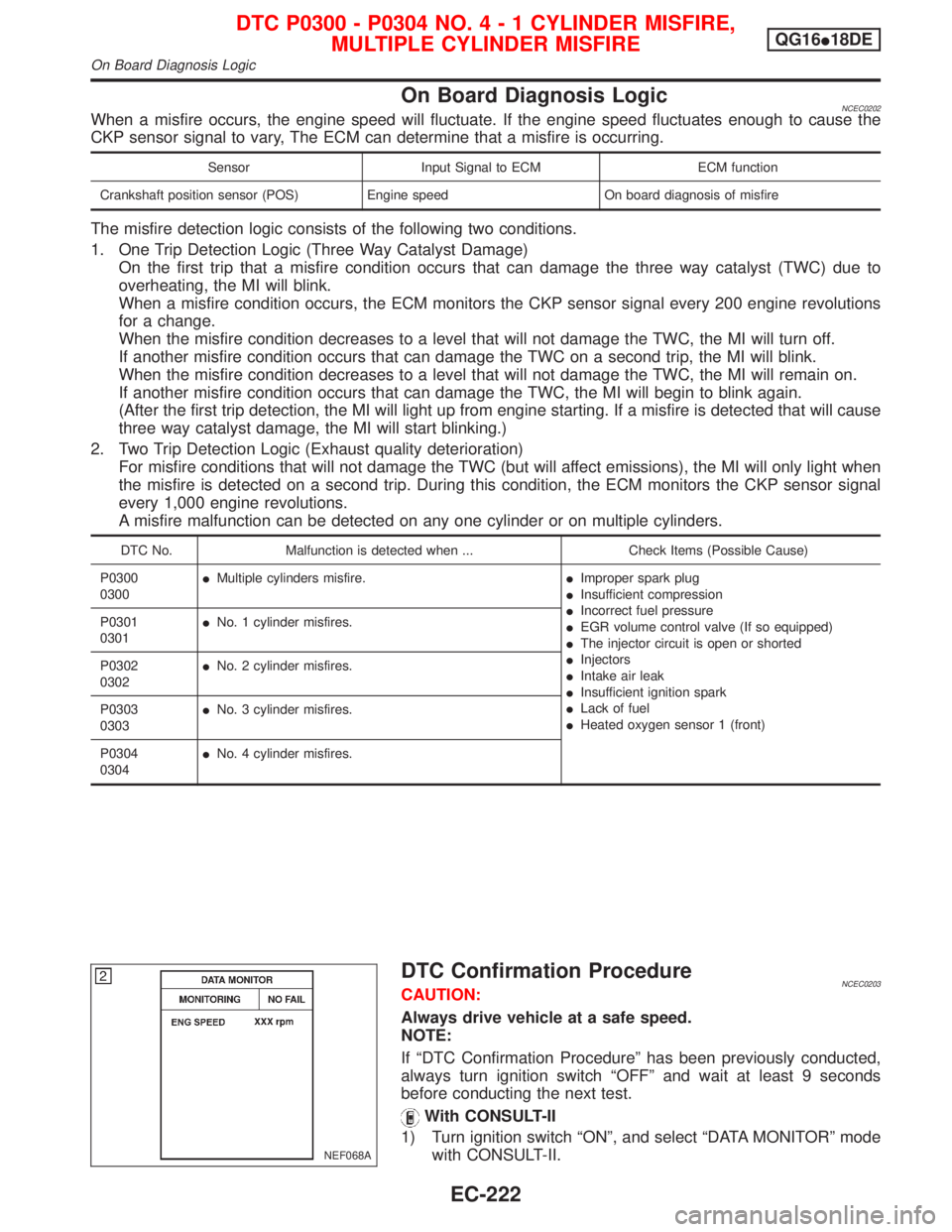
1) Turn ignition switch ªONº, and select ªDATA MONITORº mode
with CONSULT-II.
NEF068A
DTC P0300 - P0304 NO.4-1CYLINDER MISFIRE,
MULTIPLE CYLINDER MISFIREQG16I18DE
On Board Diagnosis Logic
EC-222
Page 674 of 2267
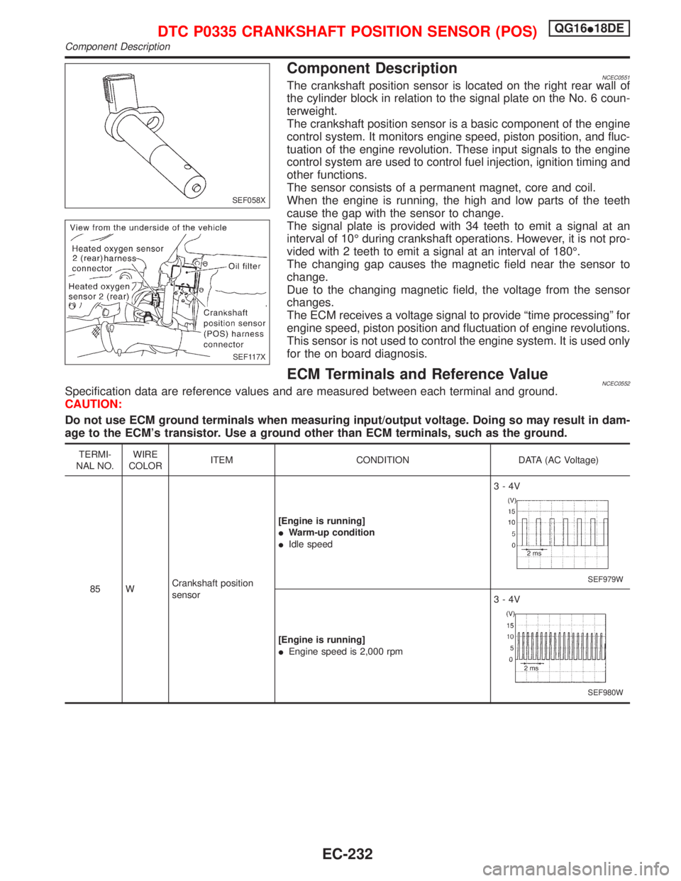
Component DescriptionNCEC0551The crankshaft position sensor is located on the right rear wall of
the cylinder block in relation to the signal plate on the No. 6 coun-
terweight.
The crankshaft position sensor is a basic component of the engine
control system. It monitors engine speed, piston position, and fluc-
tuation of the engine revolution. These input signals to the engine
control system are used to control fuel injection, ignition timing and
other functions.
The sensor consists of a permanent magnet, core and coil.
When the engine is running, the high and low parts of the teeth
cause the gap with the sensor to change.
The signal plate is provided with 34 teeth to emit a signal at an
interval of 10É during crankshaft operations. However, it is not pro-
vided with 2 teeth to emit a signal at an interval of 180É.
The changing gap causes the magnetic field near the sensor to
change.
Due to the changing magnetic field, the voltage from the sensor
changes.
The ECM receives a voltage signal to provide ªtime processingº for
engine speed, piston position and fluctuation of engine revolutions.
This sensor is not used to control the engine system. It is used only
for the on board diagnosis.
ECM Terminals and Reference ValueNCEC0552Specification data are reference values and are measured between each terminal and ground.
CAUTION:
Do not use ECM ground terminals when measuring input/output voltage. Doing so may result in dam-
age to the ECM's transistor. Use a ground other than ECM terminals, such as the ground.
TERMI-
NAL NO.WIRE
COLORITEM CONDITION DATA (AC Voltage)
85 WCrankshaft position
sensor[Engine is running]
IWarm-up condition
IIdle speed3-4V
SEF979W
[Engine is running]
IEngine speed is 2,000 rpm3-4V
SEF980W
SEF058X
SEF117X
DTC P0335 CRANKSHAFT POSITION SENSOR (POS)QG16I18DE
Component Description
EC-232
Page 680 of 2267
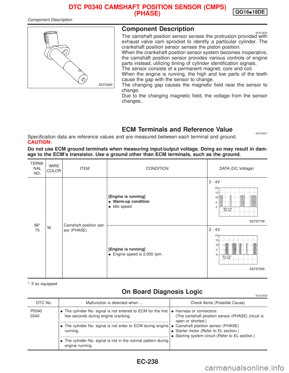
Component DescriptionNCEC0220The camshaft position sensor senses the protrusion provided with
exhaust valve cam sprocket to identify a particular cylinder. The
crankshaft position sensor senses the piston position.
When the crankshaft position sensor system becomes inoperative,
the camshaft position sensor provides various controls of engine
parts instead, utilizing timing of cylinder identification signals.
The sensor consists of a permanent magnet, core and coil.
When the engine is running, the high and low parts of the teeth
cause the gap with the sensor to change.
The changing gap causes the magnetic field near the sensor to
change.
Due to the changing magnetic field, the voltage from the sensor
changes.
ECM Terminals and Reference ValueNCEC0221Specification data are reference values and are measured between each terminal and ground.
CAUTION:
Do not use ECM ground terminals when measuring input/output voltage. Doing so may result in dam-
age to the ECM's transistor. Use a ground other than ECM terminals, such as the ground.
TERMI-
NAL
NO.WIRE
COLORITEM CONDITION DATA (DC Voltage)
66*
75WCamshaft position sen-
sor (PHASE)[Engine is running]
IWarm-up condition
IIdle speed3-4V
SEF977W
[Engine is running]
IEngine speed is 2,000 rpm3-4V
SEF978W
*: If so equipped
On Board Diagnosis LogicNCEC0222
DTC No. Malfunction is detected when ... Check Items (Possible Cause)
P0340
0340IThe cylinder No. signal is not entered to ECM for the first
few seconds during engine cranking.
.................................................................................................
IThe cylinder No. signal is not enter to ECM during engine
running.
.................................................................................................
IThe cylinder No. signal is not in the normal pattern during
engine running.IHarness or connectors
(The camshaft position sensor (PHASE) circuit is
open or shorted.)
ICamshaft position sensor (PHASE)
IStarter motor (Refer to EL section.)
IStarting system circuit (Refer to EL section.)
SEF058X
DTC P0340 CAMSHAFT POSITION SENSOR (CMPS)
(PHASE)QG16I18DE
Component Description
EC-238
Page 686 of 2267
DescriptionNCEC0227SYSTEM DESCRIPTIONNCEC0227S01
Sensor Input Signal to ECMECM func-
tionActuator
Crankshaft position sensor Engine speed
EGR control EGR volume control valve Mass air flow sensor Amount of intake air
Engine coolant temperature sensor Engine coolant temperature
Ignition switch Start signal
Throttle position sensor Throttle position
Vehicle speed sensor or ABS actuator and
electric unit (control unit)Vehicle speed
Battery Battery voltage
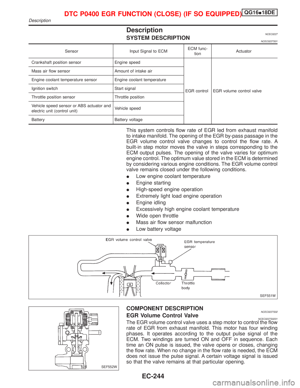
This system controls flow rate of EGR led from exhaust manifold
to intake manifold. The opening of the EGR by-pass passage in the
EGR volume control valve changes to control the flow rate. A
built-in step motor moves the valve in steps corresponding to the
ECM output pulses. The opening of the valve varies for optimum
engine control. The optimum value stored in the ECM is determined
by considering various engine conditions. The EGR volume control
valve remains closed under the following conditions.
ILow engine coolant temperature
IEngine starting
IHigh-speed engine operation
IExtremely light load engine operation
IEngine idling
IExcessively high engine coolant temperature
IWide open throttle
IMass air flow sensor malfunction
ILow battery voltage
COMPONENT DESCRIPTIONNCEC0227S02EGR Volume Control ValveNCEC0227S0201The EGR volume control valve uses a step motor to control the flow
rate of EGR from exhaust manifold. This motor has four winding
phases. It operates according to the output pulse signal of the
ECM. Two windings are turned ON and OFF in sequence. Each
time an ON pulse is issued, the valve opens or closes, changing
the flow rate. When no change in the flow rate is needed, the ECM
does not issue the pulse signal. A certain voltage signal is issued
so that the valve remains at that particular opening.
SEF551W
SEF552W
DTC P0400 EGR FUNCTION (CLOSE) (IF SO EQUIPPED)QG16I18DE
Description
EC-244
Page 687 of 2267
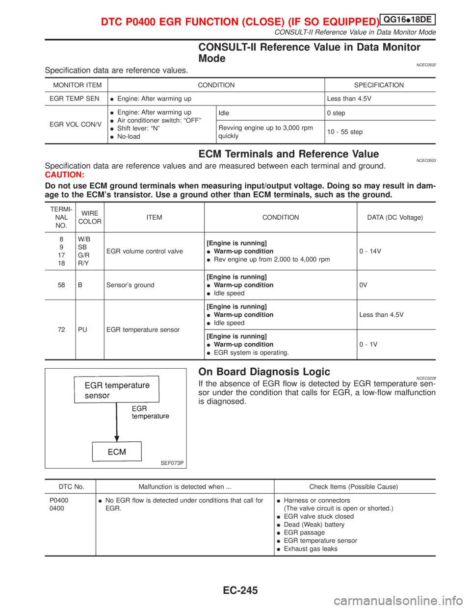
CONSULT-II Reference Value in Data Monitor
Mode
NCEC0502Specification data are reference values.
MONITOR ITEM CONDITION SPECIFICATION
EGR TEMP SENIEngine: After warming up Less than 4.5V
EGR VOL CON/VIEngine: After warming up
IAir conditioner switch: ªOFFº
IShift lever: ªNº
INo-loadIdle 0 step
Revving engine up to 3,000 rpm
quickly10 - 55 step
ECM Terminals and Reference ValueNCEC0503Specification data are reference values and are measured between each terminal and ground.
CAUTION:
Do not use ECM ground terminals when measuring input/output voltage. Doing so may result in dam-
age to the ECM's transistor. Use a ground other than ECM terminals, such as the ground.
TERMI-
NAL
NO.WIRE
COLORITEM CONDITION DATA (DC Voltage)
8
9
17
18W/B
SB
G/R
R/YEGR volume control valve[Engine is running]
IWarm-up condition
IRev engine up from 2,000 to 4,000 rpm0 - 14V
58 B Sensor's ground[Engine is running]
IWarm-up condition
IIdle speed0V
72 PU EGR temperature sensor[Engine is running]
IWarm-up condition
IIdle speedLess than 4.5V
[Engine is running]
IWarm-up condition
IEGR system is operating.0-1V
On Board Diagnosis LogicNCEC0228If the absence of EGR flow is detected by EGR temperature sen-
sor under the condition that calls for EGR, a low-flow malfunction
is diagnosed.
DTC No. Malfunction is detected when ... Check Items (Possible Cause)
P0400
0400INo EGR flow is detected under conditions that call for
EGR.IHarness or connectors
(The valve circuit is open or shorted.)
IEGR valve stuck closed
IDead (Weak) battery
IEGR passage
IEGR temperature sensor
IExhaust gas leaks
SEF073P
DTC P0400 EGR FUNCTION (CLOSE) (IF SO EQUIPPED)QG16I18DE
CONSULT-II Reference Value in Data Monitor Mode
EC-245
Page 691 of 2267
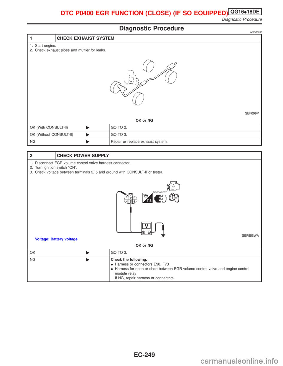
Diagnostic ProcedureNCEC0232
1 CHECK EXHAUST SYSTEM
1. Start engine.
2. Check exhaust pipes and muffler for leaks.
SEF099P
OK or NG
OK (With CONSULT-II)©GO TO 2.
OK (Without CONSULT-II)©GO TO 3.
NG©Repair or replace exhaust system.
2 CHECK POWER SUPPLY
1. Disconnect EGR volume control valve harness connector.
2. Turn ignition switch ªONº.
3. Check voltage between terminals 2, 5 and ground with CONSULT-II or tester.
DISCONNECT
SEF556WAVoltage: Battery voltage
OK or NG
OK©GO TO 3.
NG©Check the following.
IHarness or connectors E90, F73
IHarness for open or short between EGR volume control valve and engine control
module relay
If NG, repair harness or connectors.
DTC P0400 EGR FUNCTION (CLOSE) (IF SO EQUIPPED)QG16I18DE
Diagnostic Procedure
EC-249
Page 692 of 2267
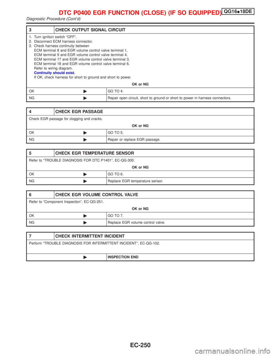
3 CHECK OUTPUT SIGNAL CIRCUIT
1. Turn ignition switch ªOFFº.
2. Disconnect ECM harness connector.
3. Check harness continuity between
ECM terminal 8 and EGR volume control valve terminal 1,
ECM terminal 9 and EGR volume control valve terminal 4,
ECM terminal 17 and EGR volume control valve terminal 3,
ECM terminal 18 and EGR volume control valve terminal 6.
Refer to wiring diagram.
Continuity should exist.
If OK, check harness for short to ground and short to power.
OK or NG
OK©GO TO 4.
NG©Repair open circuit, short to ground or short to power in harness connectors.
4 CHECK EGR PASSAGE
Check EGR passage for clogging and cracks.
OK or NG
OK©GO TO 5.
NG©Repair or replace EGR passage.
5 CHECK EGR TEMPERATURE SENSOR
Refer to ªTROUBLE DIAGNOSIS FOR DTC P1401º, EC-QG-300.
OK or NG
OK©GO TO 6.
NG©Replace EGR temperature sensor.
6 CHECK EGR VOLUME CONTROL VALVE
Refer to ªComponent Inspectionº, EC-QG-251.
OK or NG
OK©GO TO 7.
NG©Replace EGR volume control valve.
7 CHECK INTERMITTENT INCIDENT
Perform ªTROUBLE DIAGNOSIS FOR INTERMITTENT INCIDENTº, EC-QG-102.
©INSPECTION END
DTC P0400 EGR FUNCTION (CLOSE) (IF SO EQUIPPED)QG16I18DE
Diagnostic Procedure (Cont'd)
EC-250
Page 693 of 2267
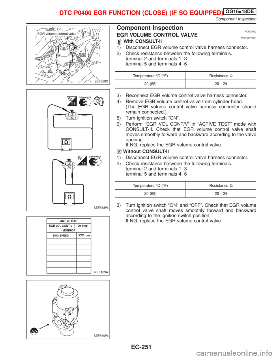
Component InspectionNCEC0233EGR VOLUME CONTROL VALVENCEC0233S01With CONSULT-II
1) Disconnect EGR volume control valve harness connector.
2) Check resistance between the following terminals.
terminal 2 and terminals 1, 3
terminal 5 and terminals 4, 6
Temperature ÉC (ÉF) ResistanceW
20 (68) 20 - 24
3) Reconnect EGR volume control valve harness connector.
4) Remove EGR volume control valve from cylinder head.
(The EGR volume control valve harness connector should
remain connected.)
5) Turn ignition switch ªONº.
6) Perform ªEGR VOL CONT/Vº in ªACTIVE TESTº mode with
CONSULT-II. Check that EGR volume control valve shaft
moves smoothly forward and backward according to the valve
opening.
If NG, replace the EGR volume control valve.
Without CONSULT-II
1) Disconnect EGR volume control valve harness connector.
2) Check resistance between the following terminals.
terminal 2 and terminals 1, 3
terminal 5 and terminals 4, 6
Temperature ÉC (ÉF) ResistanceW
20 (68) 20 - 24
3) Turn ignition switch ªONº and ªOFFº. Check that EGR volume
control valve shaft moves smoothly forward and backward
according to the ignition switch position.
If NG, replace the EGR volume control valve.
SEF069X
SEF558W
NEF109A
SEF560W
DTC P0400 EGR FUNCTION (CLOSE) (IF SO EQUIPPED)QG16I18DE
Component Inspection
EC-251