Page 1336 of 2267
YEL181C
IGNITION SWITCH
ACC or ONBATTERYIGNITION SWITCH
ON or START
FUSE
BLOCK
(J/B)BATTERY
Refer to EL-POWER.
POWER
FUSE
15A: With gasoline engine
: With diesel engine
: With XENON headlamp,
gasoline engine
: Except
CLOCKCOMBINATION
METER
(CLOCK)
CIGARETTE
LIGHTER
SOCKET
POWER
SOCKET
REFER TO THE FOLLOWING
FUSE BLOCK - Junction Box (J/B) ACCESSORY
RELAY IGNITION
SWITCH OFF
ONST
ACC
ACC
HORN, CIGARETTE LIGHTER AND CLOCK
Wiring Diagram—HORN—(Cont’d)
EL-204
Page 1337 of 2267
Type-2
YEL885C
HORN, CIGARETTE LIGHTER AND CLOCK
Wiring Diagram—HORN—(Cont’d)
EL-205
Page 1338 of 2267
YEL886C
HORN, CIGARETTE LIGHTER AND CLOCK
Wiring Diagram—HORN—(Cont’d)
EL-206
Page 1439 of 2267

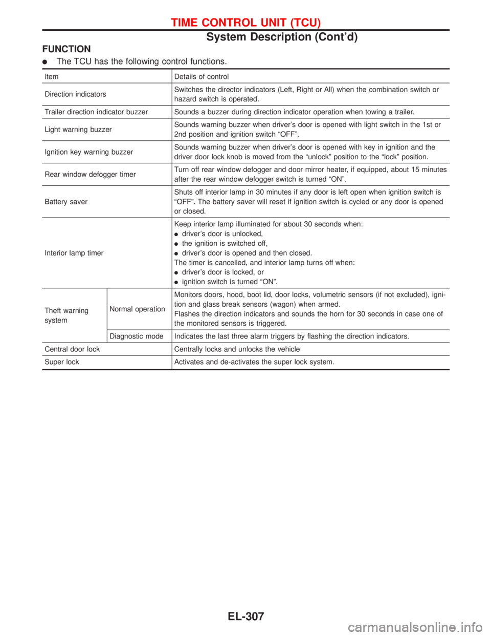
FUNCTION
�The TCU has the following control functions.
Item Details of control
Direction indicatorsSwitches the director indicators (Left, Right or All) when the combination switch or
hazard switch is operated.
Trailer direction indicator buzzer Sounds a buzzer during direction indicator operation when towing a trailer.
Light warning buzzerSounds warning buzzer when driver’s door is opened with light switch in the 1st or
2nd position and ignition switch“OFF”.
Ignition key warning buzzerSounds warning buzzer when driver’s door is opened with key in ignition and the
driver door lock knob is moved from the“unlock”position to the“lock”position.
Rear window defogger timerTurn off rear window defogger and door mirror heater, if equipped, about 15 minutes
after the rear window defogger switch is turned“ON”.
Battery saverShuts off interior lamp in 30 minutes if any door is left open when ignition switch is
“OFF”. The battery saver will reset if ignition switch is cycled or any door is opened
or closed.
Interior lamp timerKeep interior lamp illuminated for about 30 seconds when:
�driver’s door is unlocked,
�the ignition is switched off,
�driver’s door is opened and then closed.
The timer is cancelled, and interior lamp turns off when:
�driver’s door is locked, or
�ignition switch is turned“ON”.
Theft warning
systemNormal operationMonitors doors, hood, boot lid, door locks, volumetric sensors (if not excluded), igni-
tion and glass break sensors (wagon) when armed.
Flashes the direction indicators and sounds the horn for 30 seconds in case one of
the monitored sensors is triggered.
Diagnostic mode Indicates the last three alarm triggers by flashing the direction indicators.
Central door lock Centrally locks and unlocks the vehicle
Super lock Activates and de-activates the super lock system.
TIME CONTROL UNIT (TCU)
System Description (Cont’d)
EL-307
Page 1443 of 2267
Components Parts and Harness Connector
Location
NEL529 Door unlock sensor RH
Ultrasonic sub sensor
Door unlock sensor
Front door switch RH
Security indicator light
Hood switchRear door switch RH
Ultra sonic sensor
Theft warning horn
Rear door switch
Door unlock sensor LH
Door key cylinder
switch
Door unlock sensor
Front door switch LH
Ultrasonic
cancel switch
Time control unit
Theft warning horn relay
.
Door key cylinder switch
Door unlock sensor
Ultrasonic
sub sensorUltrasonic sensor
Ultrasonic cancel switch
.Trunk room/luggage
room lamp switchTime control unit
Hood switch
Theft
warning
horn
Trunk room/Luggange room lamp switch
THEFT WARNING SYSTEM
EL-311
Page 1445 of 2267

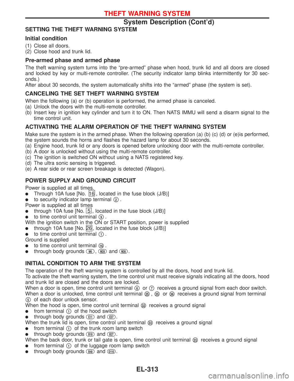
SETTING THE THEFT WARNING SYSTEM
Initial condition
(1) Close all doors.
(2) Close hood and trunk lid.
Pre-armed phase and armed phase
The theft warning system turns into the“pre-armed”phase when hood, trunk lid and all doors are closed
and locked by key or multi-remote controller. (The security indicator lamp blinks intermittently for 30 sec-
onds.)
After about 30 seconds, the system automatically shifts into the“armed”phase (the system is set).
CANCELING THE SET THEFT WARNING SYSTEM
When the following (a) or (b) operation is performed, the armed phase is canceled.
(a) Unlock the doors with the multi-remote controller.
(b) Insert key in ignition key cylinder and turn it to ON. Then NATS IMMU will send a disarm signal to the
time control unit.
ACTIVATING THE ALARM OPERATION OF THE THEFT WARNING SYSTEM
Make sure the system is in the armed phase. When the following operation (a) (b) (c) (d) or (e)is performed,
the system sounds the horns and flashes the hazard lamp for about 30 seconds.
(a) Engine hood, trunk lid or any doors is opened before unlocking door with the multi-remote controller.
(b) A door is unlocked without using the multi-remote controller.
(c) The ignition is switched ON without using a NATS registered key.
(d) The ultra sonic sensing is triggered.
(e) A rear side or rear screen breakage is detected (Wagon).
POWER SUPPLY AND GROUND CIRCUIT
Power is supplied at all times.
�Through 10A fuse [No.16 , located in the fuse block (J/B)]
�to security indicator lamp terminal�2.
Power is supplied at all times
�through 10A fuse [No.5 , located in the fuse block (J/B)]
�to time control unit terminal�9.
With the ignition switch in the ON or START position, power is supplied
�through 10A fuse [No.26 , located in the fuse block (J/B)]
�to time control unit terminal�1.
Ground is supplied
�to time control unit terminal�16.
�through body groundsM6,M28andM26.
INITIAL CONDITION TO ARM THE SYSTEM
The operation of the theft warning system is controlled by all the doors, hood and trunk lid.
To activate the theft warning system, the time control unit must receive signals indicating all the doors, hood
and trunk lid are closed and the doors are locked.
When a door is open, time control unit terminal
�6or�7receives a ground signal from each door switch.
When a door is unlocked, time control unit terminal
�25,�35or�36receives a ground signal from terminal
�5of each door unlock sensor.
When the hood is open, time control unit terminal
�32receives a ground signal
�from terminal�1of the hood switch
�through body groundsE11andE37.
When the trunk lid is open, time control unit terminal
�33receives a ground signal
�from terminal�1of the trunk room lamp switch
�through body groundsB18andB27.
When the back door, trunk or tail gate is open, time control unit terminal
�33receives a ground signal
�from terminal�1of the luggage room lamp switch
�through body groundsB48andD110.
THEFT WARNING SYSTEM
System Description (Cont’d)
EL-313
Page 1446 of 2267

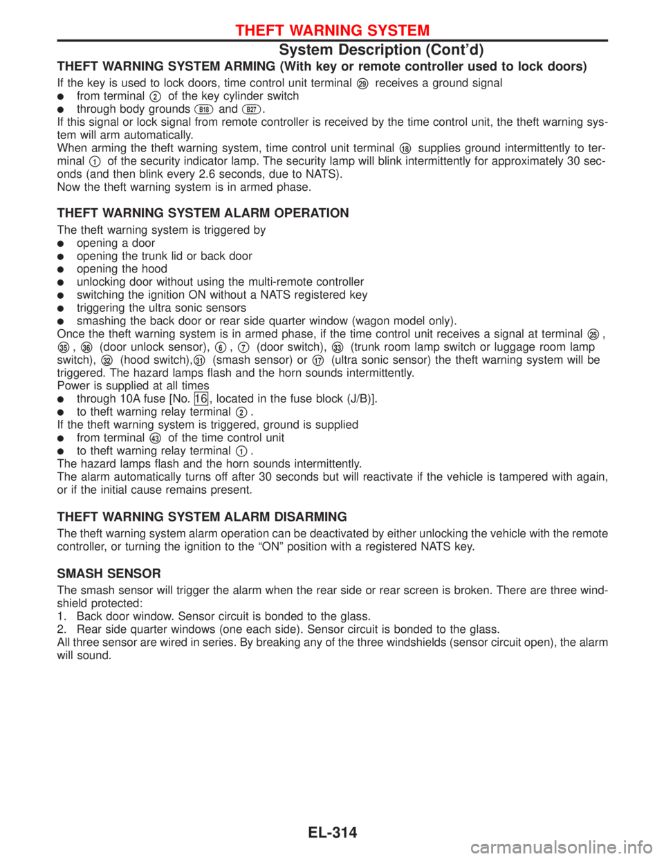
THEFT WARNING SYSTEM ARMING (With key or remote controller used to lock doors)
If the key is used to lock doors, time control unit terminal�29receives a ground signal
�from terminal�2of the key cylinder switch
�through body groundsB18andB27.
If this signal or lock signal from remote controller is received by the time control unit, the theft warning sys-
tem will arm automatically.
When arming the theft warning system, time control unit terminal
�18supplies ground intermittently to ter-
minal
�1of the security indicator lamp. The security lamp will blink intermittently for approximately 30 sec-
onds (and then blink every 2.6 seconds, due to NATS).
Now the theft warning system is in armed phase.
THEFT WARNING SYSTEM ALARM OPERATION
The theft warning system is triggered by
�opening a door
�opening the trunk lid or back door
�opening the hood
�unlocking door without using the multi-remote controller
�switching the ignition ON without a NATS registered key
�triggering the ultra sonic sensors
�smashing the back door or rear side quarter window (wagon model only).
Once the theft warning system is in armed phase, if the time control unit receives a signal at terminal
�25,
�35,�36(door unlock sensor),�6,�7(door switch),�33(trunk room lamp switch or luggage room lamp
switch),
�32(hood switch),�31(smash sensor) or�17(ultra sonic sensor) the theft warning system will be
triggered. The hazard lamps flash and the horn sounds intermittently.
Power is supplied at all times
�through 10A fuse [No.16 , located in the fuse block (J/B)].
�to theft warning relay terminal�2.
If the theft warning system is triggered, ground is supplied
�from terminal�43of the time control unit
�to theft warning relay terminal�1.
The hazard lamps flash and the horn sounds intermittently.
The alarm automatically turns off after 30 seconds but will reactivate if the vehicle is tampered with again,
or if the initial cause remains present.
THEFT WARNING SYSTEM ALARM DISARMING
The theft warning system alarm operation can be deactivated by either unlocking the vehicle with the remote
controller, or turning the ignition to the“ON”position with a registered NATS key.
SMASH SENSOR
The smash sensor will trigger the alarm when the rear side or rear screen is broken. There are three wind-
shield protected:
1. Back door window. Sensor circuit is bonded to the glass.
2. Rear side quarter windows (one each side). Sensor circuit is bonded to the glass.
All three sensor are wired in series. By breaking any of the three windshields (sensor circuit open), the alarm
will sound.
THEFT WARNING SYSTEM
System Description (Cont’d)
EL-314
Page 1451 of 2267
Models before VIN - P11U0548750
YEL213C
TIME
CONTROL
UNIT
To EL-THEFT-01
TRUNK
ROOM LAMP
SWITCHLUGGAGE
ROOM LAMP
SWITCH
THEFT
WARNING
HORN CLOSEDOPEN
CLOSEDOPEN: 4 door models
: 5 door hatchback models
: 5 door hatchback models and
wagon models
: Wagon models THEFT
WARNING
HORN
RELAY
THEFT WARNING SYSTEM
Wiring Diagram—THEFT—(Cont’d)
EL-319