Page 501 of 666

\
HEATER&
AIR CONDITIONER
SECTION
HA
MODIFICATION NOTICE:
lWiring Diagrams for manual A/C have been changed.
lAuto A/C has been added to RHD models for Europe.
lAuto A/C of LHD models for Europe have been changed.
CONTENTS
MANUAL AND AUTO
PRECAUTIONS AND PREPARATION ............... 2002
Supplemental Restraint System (SRS) ²AIR
BAG ²and ²SEAT BELT PRE-TENSIONER ².. 2002
MANUAL
TROUBLE DIAGNOSES ..................................... 2003
Wiring Diagram - HEATER -............................ 2003
Circuit Diagram - Air Conditioner..................... 2004
Wiring Diagram - A/C, M -/Except for KA
Engine Models ................................................. 2005
Wiring Diagram - A/C, M -/KA Engine LHD
Models.............................................................. 2008
Wiring Diagram - A/C, M -/KA Engine RHD
Models.............................................................. 2011
Magnet Clutch .................................................. 2014
AUTO
DESCRIPTION..................................................... 2023
Introduction ...................................................... 2023
Features ........................................................... 2023
Overview of Control System ............................ 2024
Control Operation............................................. 2024
TROUBLE DIAGNOSES ..................................... 2026 Component Location ........................................ 2026
Circuit Diagram ................................................ 2027
Wiring Diagram - A/C, A -................................ 2028
Auto Amp. Terminals and Reference Value .... 2032
Self-diagnosis................................................... 2034
How to Perform Trouble Diagnoses for Quick
and Accurate Repair ........................................ 2040
Operational Check ........................................... 2041
A/C System ...................................................... 2045
Mode Door Motor ............................................. 2047
Air Mix Door Motor........................................... 2052
Intake Door Motor ............................................ 2058
Blower Motor .................................................... 2062
Magnet Clutch .................................................. 2068
Insufficient Cooling........................................... 2075
Insufficient Heating .......................................... 2076
Noise ................................................................ 2077
Self-diagnosis................................................... 2078
Memory Function ............................................. 2079
Ambient Sensor ............................................... 2080
In-vehicle Sensor ............................................. 2082
Aspirator Motor ................................................ 2084
Sunload Sensor ............................................... 2084
Intake Sensor ................................................... 2087
When you read wiring diagrams:
+
Read GI section, ªHOW TO READ WIRING DIAGRAMSº.
+ See EL section, ªPOWER SUPPLY ROUTINGº for power distribution circuit.
When you perform trouble diagnoses, read GI section, ªHOW TO FOLLOW FLOW
CHART IN TROUBLE DIAGNOSESº and ªHOW TO PERFORM EFFICIENT DIAGNOSIS
FOR AN ELECTRICAL INCIDENTº.
HA
Page 522 of 666
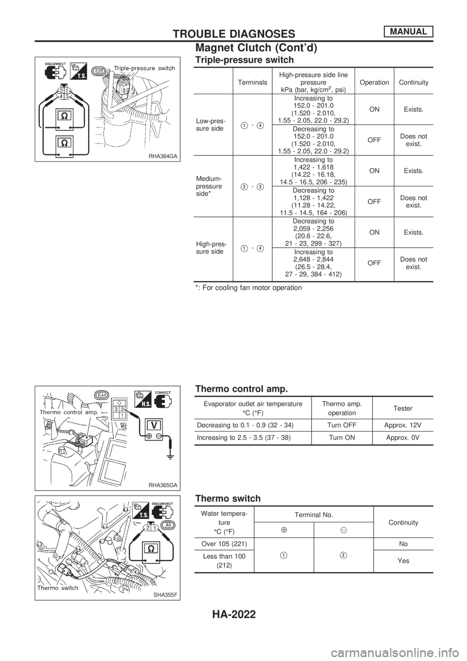
Triple-pressure switch
TerminalsHigh-pressure side line
pressure
kPa (bar, kg/cm2, psi)Operation Continuity
Low-pres-
sure side
V1-V4
Increasing to
152.0 - 201.0
(1.520 - 2.010,
1.55 - 2.05, 22.0 - 29.2)ON Exists.
Decreasing to
152.0 - 201.0
(1.520 - 2.010,
1.55 - 2.05, 22.0 - 29.2)OFFDoes not
exist.
Medium-
pressure
side*
V2-V3
Increasing to
1,422 - 1,618
(14.22 - 16.18,
14.5 - 16.5, 206 - 235)ON Exists.
Decreasing to
1,128 - 1,422
(11.28 - 14.22,
11.5 - 14.5, 164 - 206)OFFDoes not
exist.
High-pres-
sure side
V1-V4
Decreasing to
2,059 - 2,256
(20.6 - 22.6,
21 - 23, 299 - 327)ON Exists.
Increasing to
2,648 - 2,844
(26.5 - 28.4,
27 - 29, 384 - 412)OFFDoes not
exist.
*: For cooling fan motor operation
Thermo control amp.
Evaporator outlet air temperature
ÉC (ÉF)Thermo amp.
operationTester
Decreasing to 0.1 - 0.9 (32 - 34) Turn OFF Approx. 12V
Increasing to 2.5 - 3.5 (37 - 38) Turn ON Approx. 0V
Thermo switch
Water tempera-
ture
ÉC (ÉF)Terminal No.
Continuity
Å@
Over 105 (221)
V1V2
No
Less than 100
(212)Yes
RHA364GA
RHA365GA
SHA355F
TROUBLE DIAGNOSESMANUAL
Magnet Clutch (Cont'd)
HA-2022
Page 540 of 666
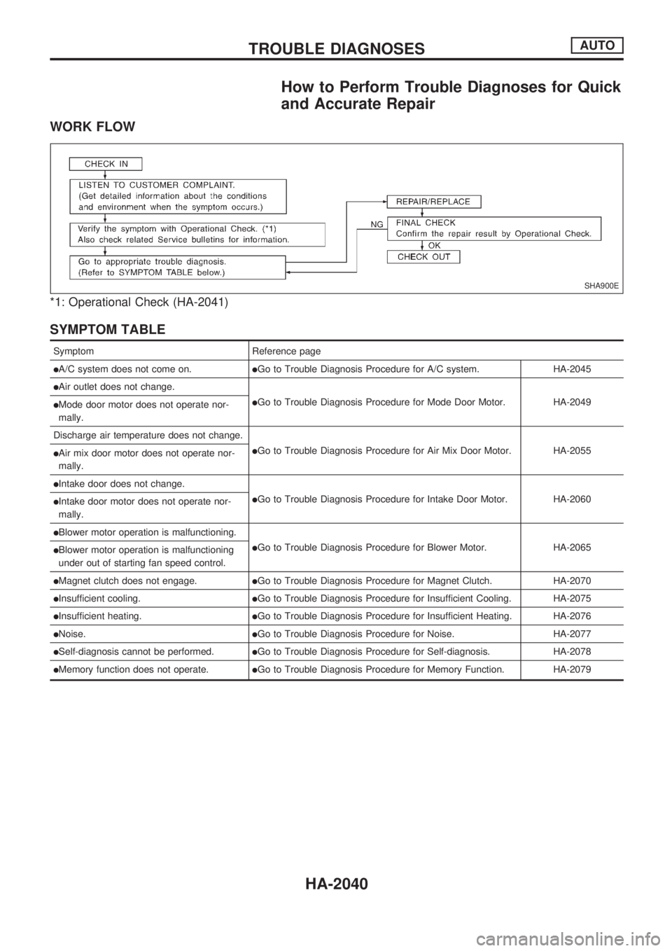
How to Perform Trouble Diagnoses for Quick
and Accurate Repair
WORK FLOW
*1: Operational Check (HA-2041)
SYMPTOM TABLE
Symptom Reference page
lA/C system does not come on.lGo to Trouble Diagnosis Procedure for A/C system. HA-2045
lAir outlet does not change.
lGo to Trouble Diagnosis Procedure for Mode Door Motor. HA-2049lMode door motor does not operate nor-
mally.
Discharge air temperature does not change.
lGo to Trouble Diagnosis Procedure for Air Mix Door Motor. HA-2055lAir mix door motor does not operate nor-
mally.
lIntake door does not change.
lGo to Trouble Diagnosis Procedure for Intake Door Motor. HA-2060lIntake door motor does not operate nor-
mally.
lBlower motor operation is malfunctioning.
lGo to Trouble Diagnosis Procedure for Blower Motor. HA-2065lBlower motor operation is malfunctioning
under out of starting fan speed control.
lMagnet clutch does not engage.lGo to Trouble Diagnosis Procedure for Magnet Clutch. HA-2070
lInsufficient cooling.lGo to Trouble Diagnosis Procedure for Insufficient Cooling. HA-2075
lInsufficient heating.lGo to Trouble Diagnosis Procedure for Insufficient Heating. HA-2076
lNoise.lGo to Trouble Diagnosis Procedure for Noise. HA-2077
lSelf-diagnosis cannot be performed.lGo to Trouble Diagnosis Procedure for Self-diagnosis. HA-2078
lMemory function does not operate.lGo to Trouble Diagnosis Procedure for Memory Function. HA-2079
SHA900E
TROUBLE DIAGNOSESAUTO
HA-2040
Page 543 of 666
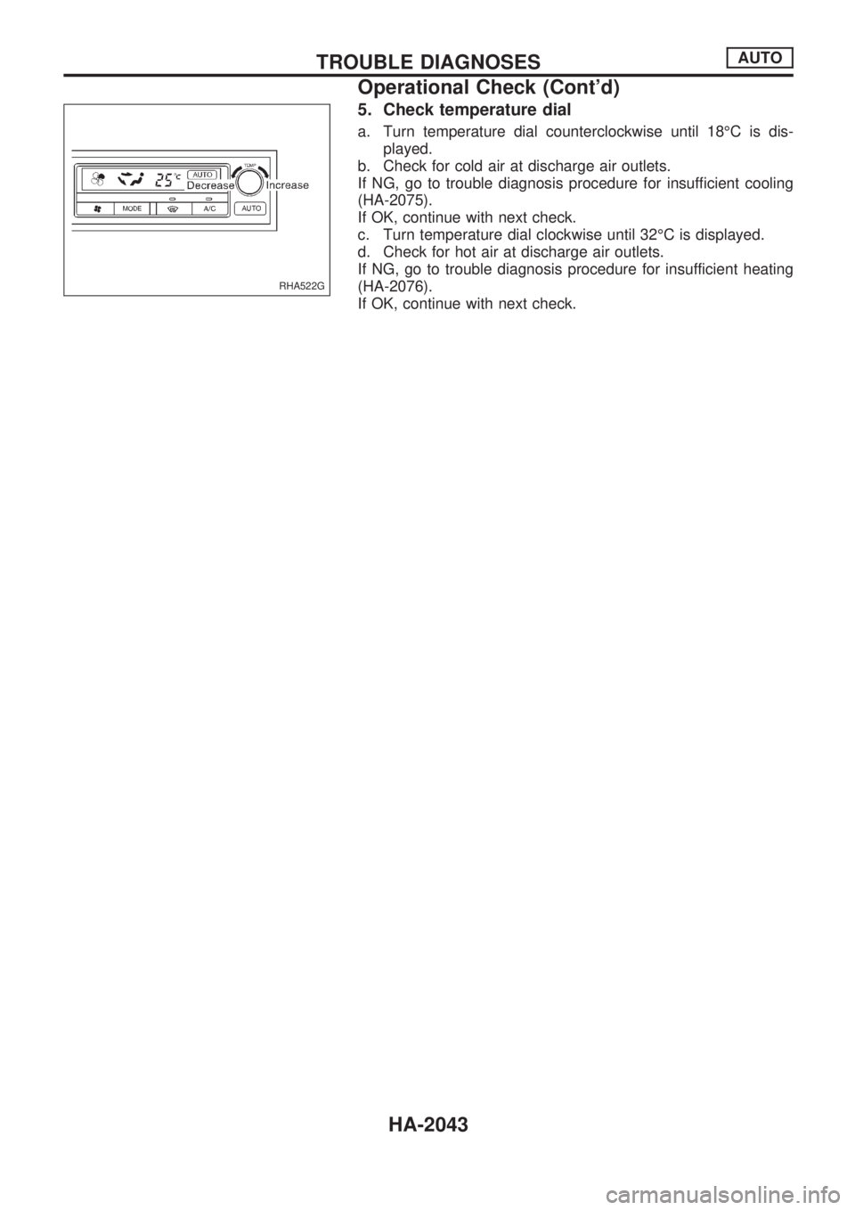
5. Check temperature dial
a. Turn temperature dial counterclockwise until 18ÉC is dis-
played.
b. Check for cold air at discharge air outlets.
If NG, go to trouble diagnosis procedure for insufficient cooling
(HA-2075).
If OK, continue with next check.
c. Turn temperature dial clockwise until 32ÉC is displayed.
d. Check for hot air at discharge air outlets.
If NG, go to trouble diagnosis procedure for insufficient heating
(HA-2076).
If OK, continue with next check.
RHA522G
TROUBLE DIAGNOSESAUTO
Operational Check (Cont'd)
HA-2043
Page 564 of 666
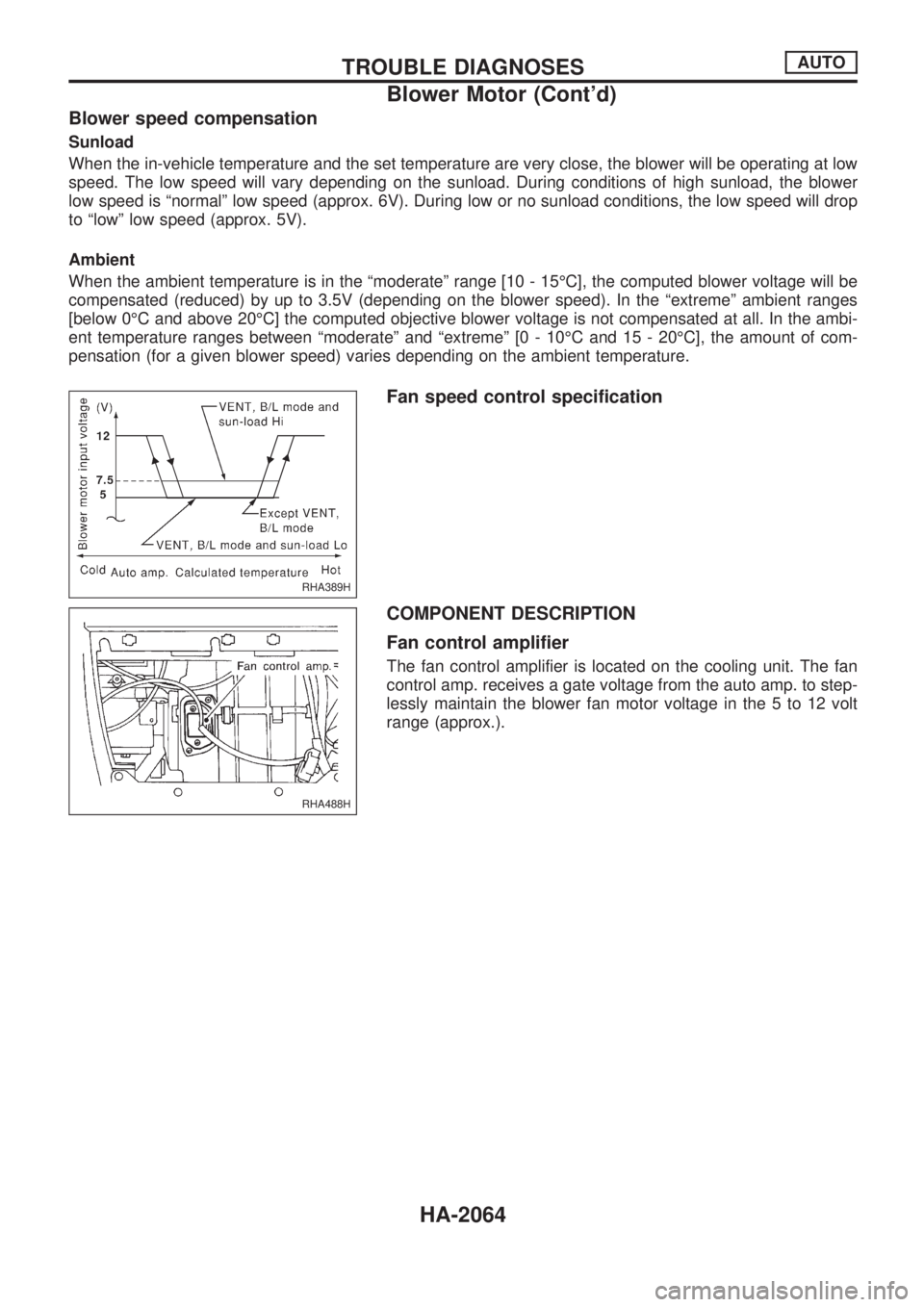
Blower speed compensation
Sunload
When the in-vehicle temperature and the set temperature are very close, the blower will be operating at low
speed. The low speed will vary depending on the sunload. During conditions of high sunload, the blower
low speed is ªnormalº low speed (approx. 6V). During low or no sunload conditions, the low speed will drop
to ªlowº low speed (approx. 5V).
Ambient
When the ambient temperature is in the ªmoderateº range [10 - 15ÉC], the computed blower voltage will be
compensated (reduced) by up to 3.5V (depending on the blower speed). In the ªextremeº ambient ranges
[below 0ÉC and above 20ÉC] the computed objective blower voltage is not compensated at all. In the ambi-
ent temperature ranges between ªmoderateº and ªextremeº [0 - 10ÉC and 15 - 20ÉC], the amount of com-
pensation (for a given blower speed) varies depending on the ambient temperature.
Fan speed control specification
COMPONENT DESCRIPTION
Fan control amplifier
The fan control amplifier is located on the cooling unit. The fan
control amp. receives a gate voltage from the auto amp. to step-
lessly maintain the blower fan motor voltage in the 5 to 12 volt
range (approx.).
RHA389H
RHA488H
TROUBLE DIAGNOSESAUTO
Blower Motor (Cont'd)
HA-2064
Page 573 of 666
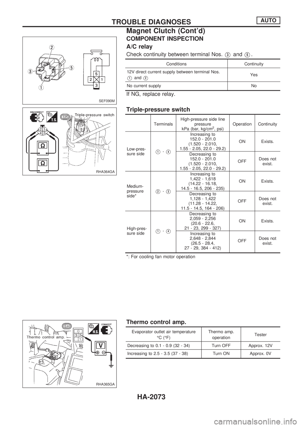
COMPONENT INSPECTION
A/C relay
Check continuity between terminal Nos.V3andV5.
Conditions Continuity
12V direct current supply between terminal Nos.
V1andV2Yes
No current supply No
If NG, replace relay.
Triple-pressure switch
TerminalsHigh-pressure side line
pressure
kPa (bar, kg/cm2, psi)Operation Continuity
Low-pres-
sure side
V1-V4
Increasing to
152.0 - 201.0
(1.520 - 2.010,
1.55 - 2.05, 22.0 - 29.2)ON Exists.
Decreasing to
152.0 - 201.0
(1.520 - 2.010,
1.55 - 2.05, 22.0 - 29.2)OFFDoes not
exist.
Medium-
pressure
side*
V2-V3
Increasing to
1,422 - 1,618
(14.22 - 16.18,
14.5 - 16.5, 206 - 235)ON Exists.
Decreasing to
1,128 - 1,422
(11.28 - 14.22,
11.5 - 14.5, 164 - 206)OFFDoes not
exist.
High-pres-
sure side
V1-V4
Decreasing to
2,059 - 2,256
(20.6 - 22.6,
21 - 23, 299 - 327)ON Exists.
Increasing to
2,648 - 2,844
(26.5 - 28.4,
27 - 29, 384 - 412)OFFDoes not
exist.
*: For cooling fan motor operation
Thermo control amp.
Evaporator outlet air temperature
ÉC (ÉF)Thermo amp.
operationTester
Decreasing to 0.1 - 0.9 (32 - 34) Turn OFF Approx. 12V
Increasing to 2.5 - 3.5 (37 - 38) Turn ON Approx. 0V
SEF090M
RHA364GA
RHA365GA
TROUBLE DIAGNOSESAUTO
Magnet Clutch (Cont'd)
HA-2073
Page 575 of 666
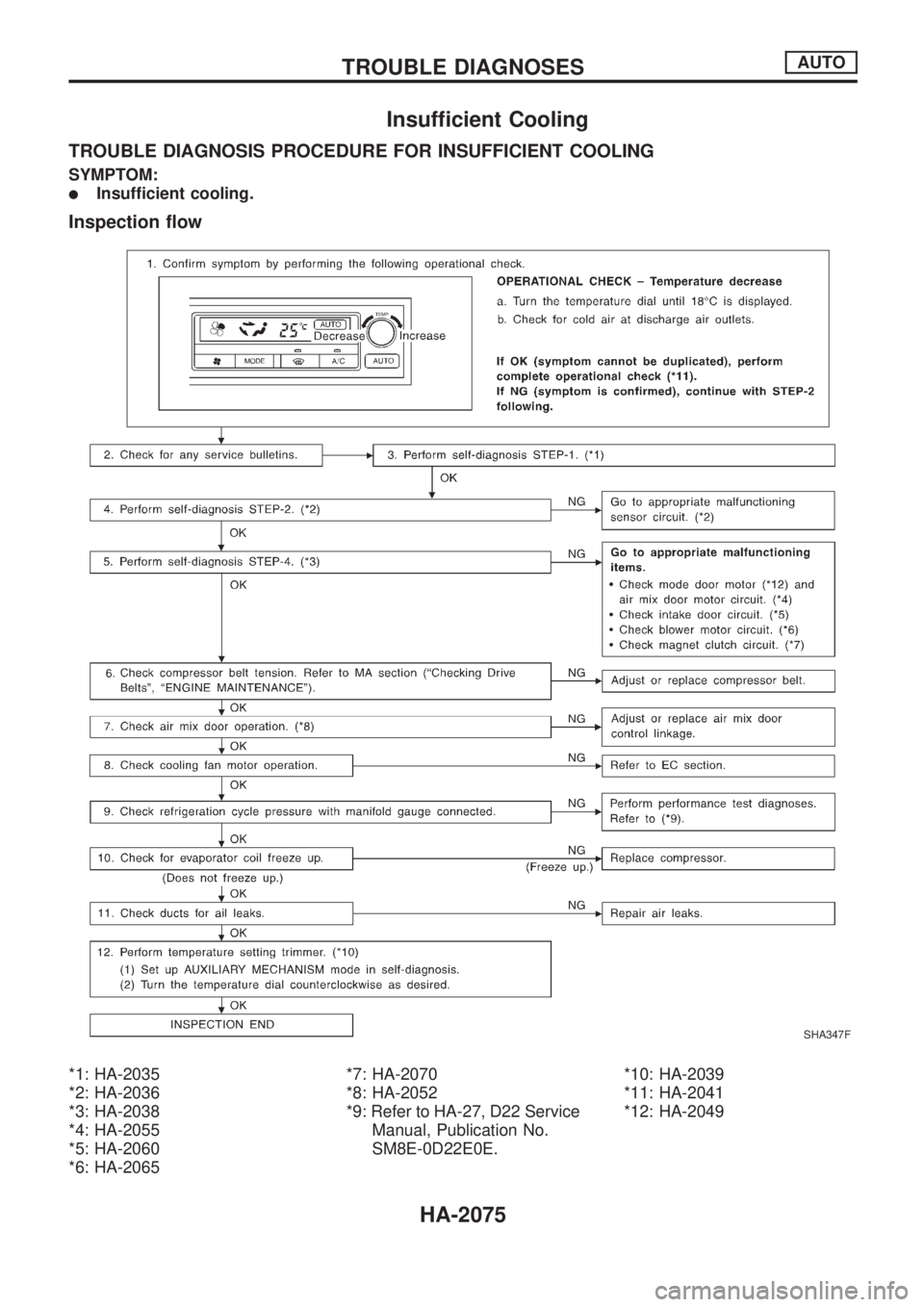
Insufficient Cooling
TROUBLE DIAGNOSIS PROCEDURE FOR INSUFFICIENT COOLING
SYMPTOM:
lInsufficient cooling.
Inspection flow
*1: HA-2035
*2: HA-2036
*3: HA-2038
*4: HA-2055
*5: HA-2060
*6: HA-2065*7: HA-2070
*8: HA-2052
*9: Refer to HA-27, D22 Service
Manual, Publication No.
SM8E-0D22E0E.*10: HA-2039
*11: HA-2041
*12: HA-2049
SHA347F
TROUBLE DIAGNOSESAUTO
HA-2075
Page 587 of 666
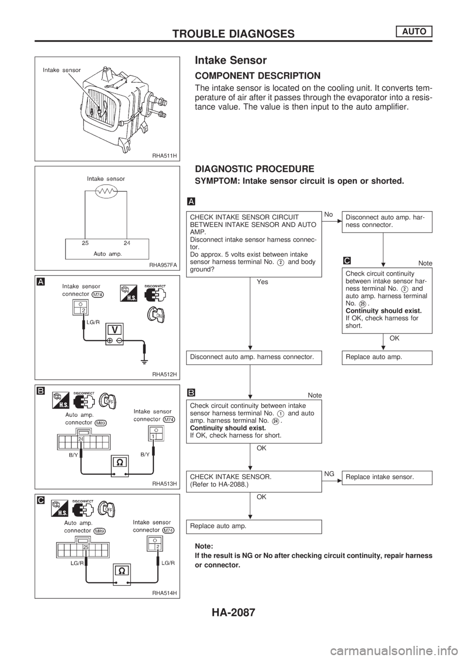
Intake Sensor
COMPONENT DESCRIPTION
The intake sensor is located on the cooling unit. It converts tem-
perature of air after it passes through the evaporator into a resis-
tance value. The value is then input to the auto amplifier.
DIAGNOSTIC PROCEDURE
SYMPTOM: Intake sensor circuit is open or shorted.
CHECK INTAKE SENSOR CIRCUIT
BETWEEN INTAKE SENSOR AND AUTO
AMP.
Disconnect intake sensor harness connec-
tor.
Do approx. 5 volts exist between intake
sensor harness terminal No.
V2and body
ground?
Yes
cNo
Disconnect auto amp. har-
ness connector.
Note
Check circuit continuity
between intake sensor har-
ness terminal No.
V2and
auto amp. harness terminal
No.
V25.
Continuity should exist.
If OK, check harness for
short.
OK
Disconnect auto amp. harness connector.
Replace auto amp.
Note
Check circuit continuity between intake
sensor harness terminal No.
V1and auto
amp. harness terminal No.
V24.
Continuity should exist.
If OK, check harness for short.
OK
CHECK INTAKE SENSOR.
(Refer to HA-2088.)
OK
cNG
Replace intake sensor.
Replace auto amp.
Note:
If the result is NG or No after checking circuit continuity, repair harness
or connector.
RHA511H
RHA957FA
RHA512H
RHA513H
RHA514H
.
..
.
.
.
TROUBLE DIAGNOSESAUTO
HA-2087