1999 NISSAN PICK-UP alternator
[x] Cancel search: alternatorPage 81 of 666
WARNING LAMPS.............................................. 2072
Schematic ........................................................ 2072
Wiring Diagram - WARN -/Gasoline Engine.... 2073
Wiring Diagram - WARN -/Diesel Engine ........ 2078
Electrical Components Inspection ................... 2083
Wiring Diagram - CHIME -/LHD Models.......... 2084
Wiring Diagram - CHIME -/RHD Models ......... 2085
FRONT WIPER AND WASHER.......................... 2086
Wiring Diagram - WIPER -/LHD Models with
Intermittent ....................................................... 2086
Wiring Diagram - WIPER -/LHD Models
without Intermittent........................................... 2087
Wiring Diagram - WIPER -/RHD M/T Models
with Intermittent................................................ 2088
Wiring Diagram - WIPER -/RHD Models
without Intermittent........................................... 2090
HEADLAMP WASHER........................................ 2092
Wiring Diagram - HLC - ................................... 2092
HORN................................................................... 2093
Wiring Diagram - HORN -................................ 2093
CIGARETTE LIGHTER........................................ 2094
Wiring Diagram - CIGAR - ............................... 2094
CLOCK................................................................. 2095
Wiring Diagram - CLOCK - .............................. 2095
REAR WINDOW DEFOGGER AND MIRROR
DEFOGGER......................................................... 2096
Wiring Diagram - DEF -/LHD Models .............. 2096
Wiring Diagram - DEF -/RHD Models ............. 2097
Electrical Components Inspection ................... 2098
AUDIO.................................................................. 2099
Wiring Diagram - AUDIO -/LHD Models
Type-2 .............................................................. 2099
Wiring Diagram - AUDIO -/LHD Models
Type-3 .............................................................. 2100
Wiring Diagram - AUDIO -/RHD Models ......... 2102
AUDIO ANTENNA............................................... 2103
Power Antenna/Wiring Diagram - P/ANT - ...... 2103
POWER DOOR MIRROR.................................... 2104
Wiring Diagram - MIRROR -/LHD Models....... 2104
Wiring Diagram - MIRROR -/RHD Models ...... 2105
HEATED SEAT.................................................... 2106
Wiring Diagram - H/SEAT - ............................. 2106
POWER WINDOW............................................... 2108
Schematic/Without Interruption Detection
Function ........................................................... 2108Wiring Diagram - WINDOW -/Without
Interruption Detection Function........................ 2109
Trouble Diagnoses/Without Interruption
Detection Function ........................................... 2113
System Description/With Interruption Detection
Function ........................................................... 2114
Schematic/With Interruption Detection
Function ........................................................... 2115
Wiring Diagram - WINDOW -/With Interruption
Detection Function ........................................... 2116
Trouble Diagnoses/With Interruption Detection
Function ........................................................... 2120
POWER DOOR LOCK......................................... 2122
System Description .......................................... 2122
Wiring Diagram - D/LOCK - ............................. 2123
Trouble Diagnosis ............................................ 2125
MULTI-REMOTE CONTROL SYSTEM............... 2129
System Description .......................................... 2129
Schematic ........................................................ 2130
Wiring Diagram - MULTI - ............................... 2131
Trouble Diagnoses ........................................... 2135
ID Code Entry Procedure ................................ 2139
NATS (Nissan Anti-Theft System)/Models with
KA24E.................................................................. 2140
Wiring Diagram - NATS -................................. 2140
NATS (Nissan Anti-Theft System)/Diesel
engine.................................................................. 2141
Wiring Diagram - NATS -/LHD Models............ 2141
Wiring Diagram - NATS -/RHD Models ........... 2142
LOCATION OF ELECTRICAL UNITS................. 2143
Engine Compartment ....................................... 2143
Passenger Compartment ................................. 2144
HARNESS LAYOUT............................................ 2146
Main Harness ................................................... 2146
Engine Room Harness..................................... 2152
Engine Control Harness................................... 2160
Alternator Harness ........................................... 2164
Instrument Harness.......................................... 2165
Room Lamp Harness/LHD Models .................. 2166
Room Lamp Harness/RHD Models ................. 2167
Chassis Harness and Tail Harness ................. 2168
Front Door Harness (LH side) ......................... 2169
Front Door Harness (RH side)......................... 2170
WIRING DIAGRAM CODES (CELL CODES)..... 2171
WIRING DIAGRAM REFERENCE CHART
COOLING FAN .......................................................................................................... LC SECTION
ECCS, IGNITION SYSTEM, QUICK-GLOW SYSTEM, FUEL HEATER SYSTEM .. EC SECTION
ANTI-LOCK BRAKE SYSTEM .................................................................................. BR SECTION
SRS ``AIR BAG'' ........................................................................................................ RS SECTION
HEATER AND AIR CONDITIONER .......................................................................... HA SECTION
EL-2002
Page 95 of 666
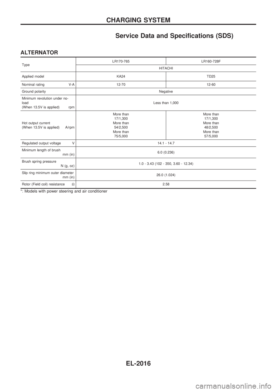
Service Data and Specifications (SDS)
ALTERNATOR
TypeLR170-765 LR160-728F
HITACHI
Applied model KA24 TD25
Nominal rating V-A 12-70 12-60
Ground polarityNegative
Minimum revolution under no-
load
(When 13.5V is applied) rpmLess than 1,000
Hot output current
(When 13.5V is applied) A/rpmMore than
17/1,300
More than
54/2,500
More than
75/5,000More than
17/1,300
More than
48/2,500
More than
57/5,000
Regulated output voltage V 14.1 - 14.7
Minimum length of brush
mm (in)6.0 (0.236)
Brush spring pressure
N (g, oz)1.0 - 3.43 (102 - 350, 3.60 - 12.34)
Slip ring minimum outer diameter
mm (in)26.0 (1.024)
Rotor (Field coil) resistanceW2.58
*: Models with power steering and air conditioner
CHARGING SYSTEM
EL-2016
Page 243 of 666
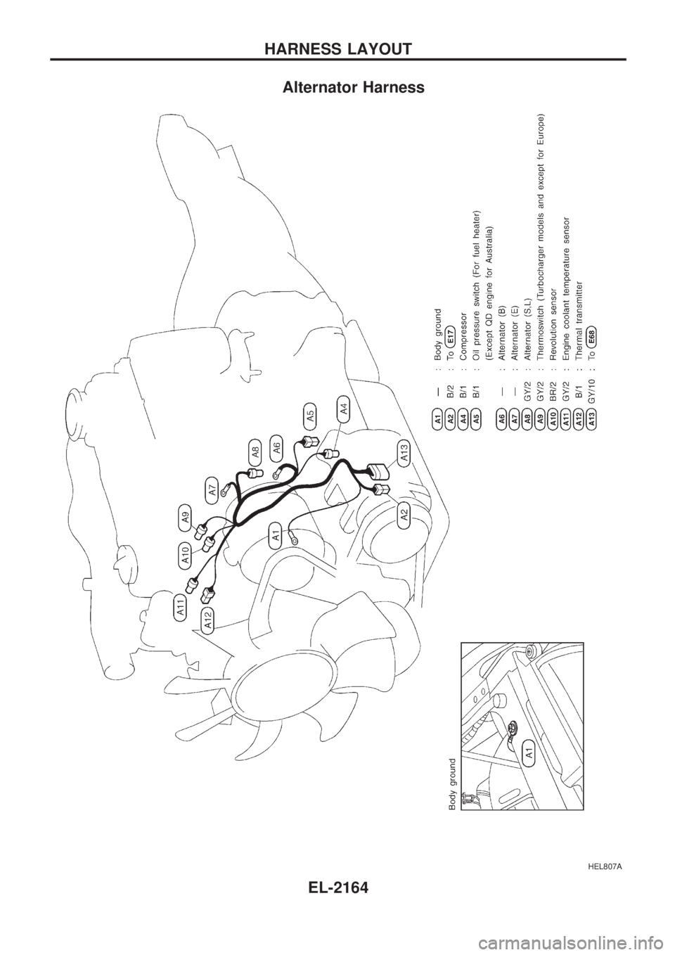
Alternator Harness
HEL807A
HARNESS LAYOUT
EL-2164
Page 253 of 666
WARNING LAMPS.............................................. 2072
Schematic ........................................................ 2072
Wiring Diagram - WARN -/Gasoline Engine.... 2073
Wiring Diagram - WARN -/Diesel Engine ........ 2078
Electrical Components Inspection ................... 2083
Wiring Diagram - CHIME -/LHD Models.......... 2084
Wiring Diagram - CHIME -/RHD Models ......... 2085
FRONT WIPER AND WASHER.......................... 2086
Wiring Diagram - WIPER -/LHD Models with
Intermittent ....................................................... 2086
Wiring Diagram - WIPER -/LHD Models
without Intermittent........................................... 2087
Wiring Diagram - WIPER -/RHD M/T Models
with Intermittent................................................ 2088
Wiring Diagram - WIPER -/RHD Models
without Intermittent........................................... 2090
HEADLAMP WASHER........................................ 2092
Wiring Diagram - HLC - ................................... 2092
HORN................................................................... 2093
Wiring Diagram - HORN -................................ 2093
CIGARETTE LIGHTER........................................ 2094
Wiring Diagram - CIGAR - ............................... 2094
CLOCK................................................................. 2095
Wiring Diagram - CLOCK - .............................. 2095
REAR WINDOW DEFOGGER AND MIRROR
DEFOGGER......................................................... 2096
Wiring Diagram - DEF -/LHD Models .............. 2096
Wiring Diagram - DEF -/RHD Models ............. 2097
Electrical Components Inspection ................... 2098
AUDIO.................................................................. 2099
Wiring Diagram - AUDIO -/LHD Models
Type-2 .............................................................. 2099
Wiring Diagram - AUDIO -/LHD Models
Type-3 .............................................................. 2100
Wiring Diagram - AUDIO -/RHD Models ......... 2102
AUDIO ANTENNA............................................... 2103
Power Antenna/Wiring Diagram - P/ANT - ...... 2103
POWER DOOR MIRROR.................................... 2104
Wiring Diagram - MIRROR -/LHD Models....... 2104
Wiring Diagram - MIRROR -/RHD Models ...... 2105
HEATED SEAT.................................................... 2106
Wiring Diagram - H/SEAT - ............................. 2106
POWER WINDOW............................................... 2108
Schematic/Without Interruption Detection
Function ........................................................... 2108Wiring Diagram - WINDOW -/Without
Interruption Detection Function........................ 2109
Trouble Diagnoses/Without Interruption
Detection Function ........................................... 2113
System Description/With Interruption Detection
Function ........................................................... 2114
Schematic/With Interruption Detection
Function ........................................................... 2115
Wiring Diagram - WINDOW -/With Interruption
Detection Function ........................................... 2116
Trouble Diagnoses/With Interruption Detection
Function ........................................................... 2120
POWER DOOR LOCK......................................... 2122
System Description .......................................... 2122
Wiring Diagram - D/LOCK - ............................. 2123
Trouble Diagnosis ............................................ 2125
MULTI-REMOTE CONTROL SYSTEM............... 2129
System Description .......................................... 2129
Schematic ........................................................ 2130
Wiring Diagram - MULTI - ............................... 2131
Trouble Diagnoses ........................................... 2135
ID Code Entry Procedure ................................ 2139
NATS (Nissan Anti-Theft System)/Models with
KA24E.................................................................. 2140
Wiring Diagram - NATS -................................. 2140
NATS (Nissan Anti-Theft System)/Diesel
engine.................................................................. 2141
Wiring Diagram - NATS -/LHD Models............ 2141
Wiring Diagram - NATS -/RHD Models ........... 2142
LOCATION OF ELECTRICAL UNITS................. 2143
Engine Compartment ....................................... 2143
Passenger Compartment ................................. 2144
HARNESS LAYOUT............................................ 2146
Main Harness ................................................... 2146
Engine Room Harness..................................... 2152
Engine Control Harness................................... 2160
Alternator Harness ........................................... 2164
Instrument Harness.......................................... 2165
Room Lamp Harness/LHD Models .................. 2166
Room Lamp Harness/RHD Models ................. 2167
Chassis Harness and Tail Harness ................. 2168
Front Door Harness (LH side) ......................... 2169
Front Door Harness (RH side)......................... 2170
WIRING DIAGRAM CODES (CELL CODES)..... 2171
WIRING DIAGRAM REFERENCE CHART
COOLING FAN .......................................................................................................... LC SECTION
ECCS, IGNITION SYSTEM, QUICK-GLOW SYSTEM, FUEL HEATER SYSTEM .. EC SECTION
ANTI-LOCK BRAKE SYSTEM .................................................................................. BR SECTION
SRS ``AIR BAG'' ........................................................................................................ RS SECTION
HEATER AND AIR CONDITIONER .......................................................................... HA SECTION
EL-2002
Page 267 of 666
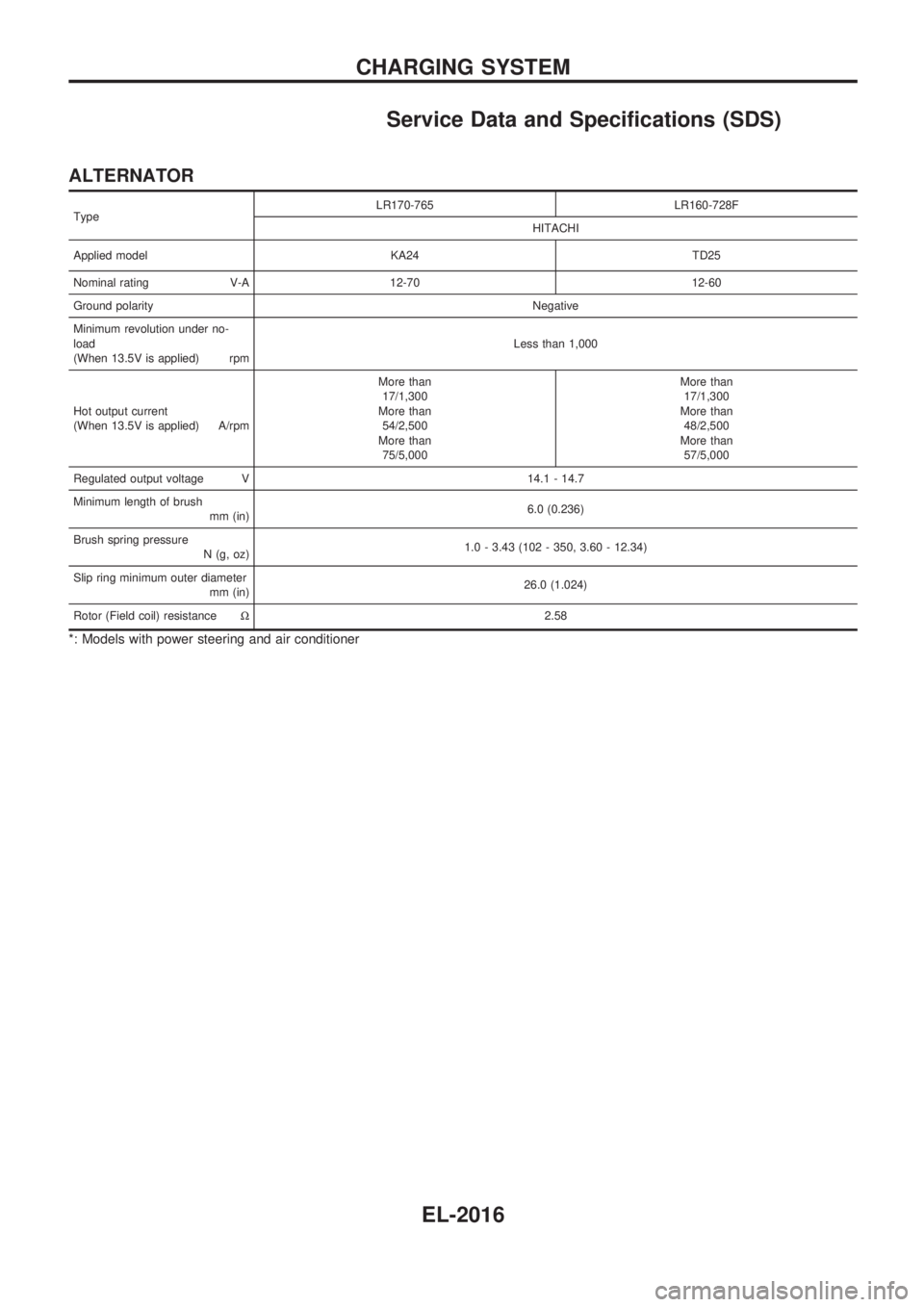
Service Data and Specifications (SDS)
ALTERNATOR
TypeLR170-765 LR160-728F
HITACHI
Applied model KA24 TD25
Nominal rating V-A 12-70 12-60
Ground polarityNegative
Minimum revolution under no-
load
(When 13.5V is applied) rpmLess than 1,000
Hot output current
(When 13.5V is applied) A/rpmMore than
17/1,300
More than
54/2,500
More than
75/5,000More than
17/1,300
More than
48/2,500
More than
57/5,000
Regulated output voltage V 14.1 - 14.7
Minimum length of brush
mm (in)6.0 (0.236)
Brush spring pressure
N (g, oz)1.0 - 3.43 (102 - 350, 3.60 - 12.34)
Slip ring minimum outer diameter
mm (in)26.0 (1.024)
Rotor (Field coil) resistanceW2.58
*: Models with power steering and air conditioner
CHARGING SYSTEM
EL-2016
Page 415 of 666
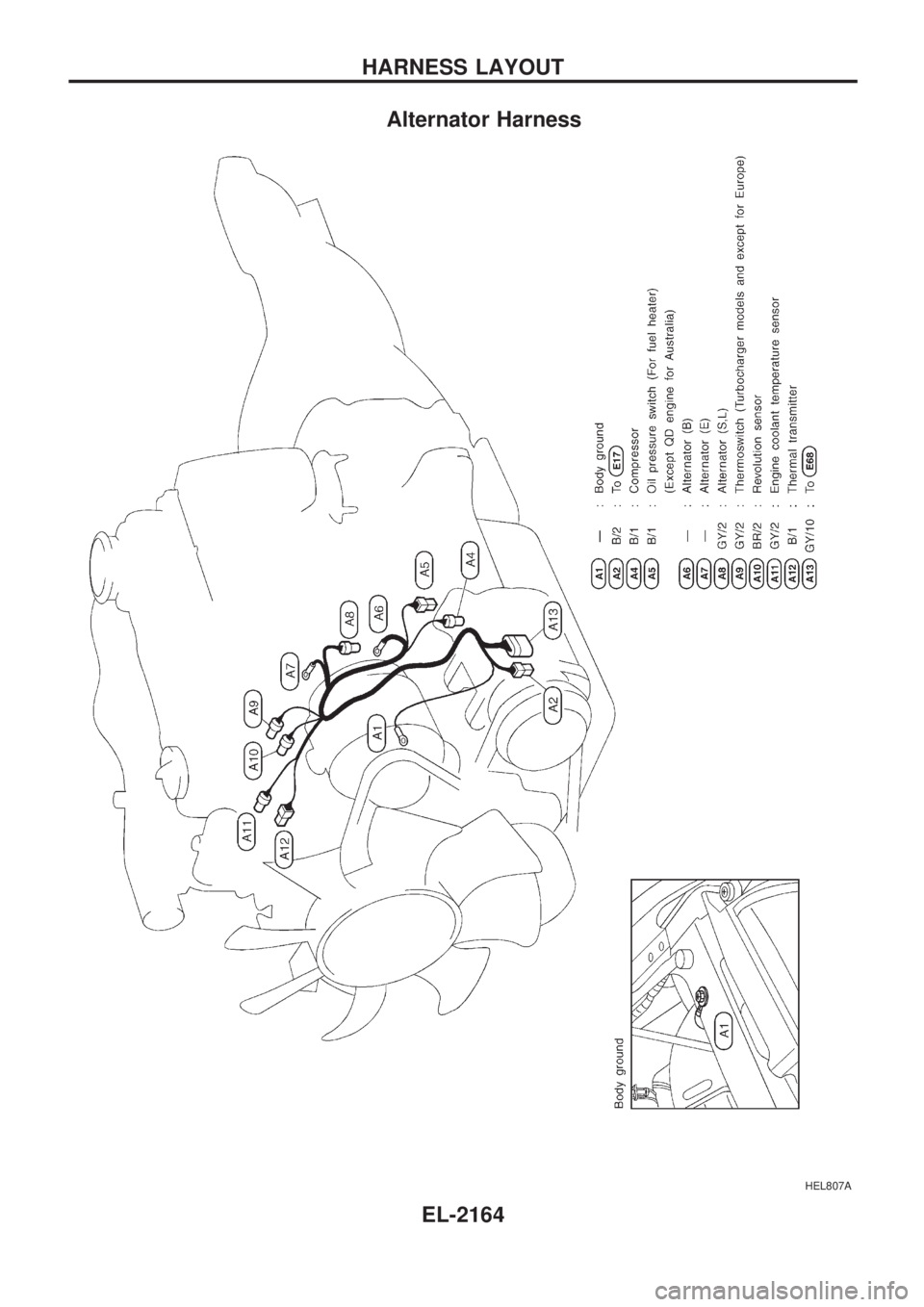
Alternator Harness
HEL807A
HARNESS LAYOUT
EL-2164
Page 444 of 666
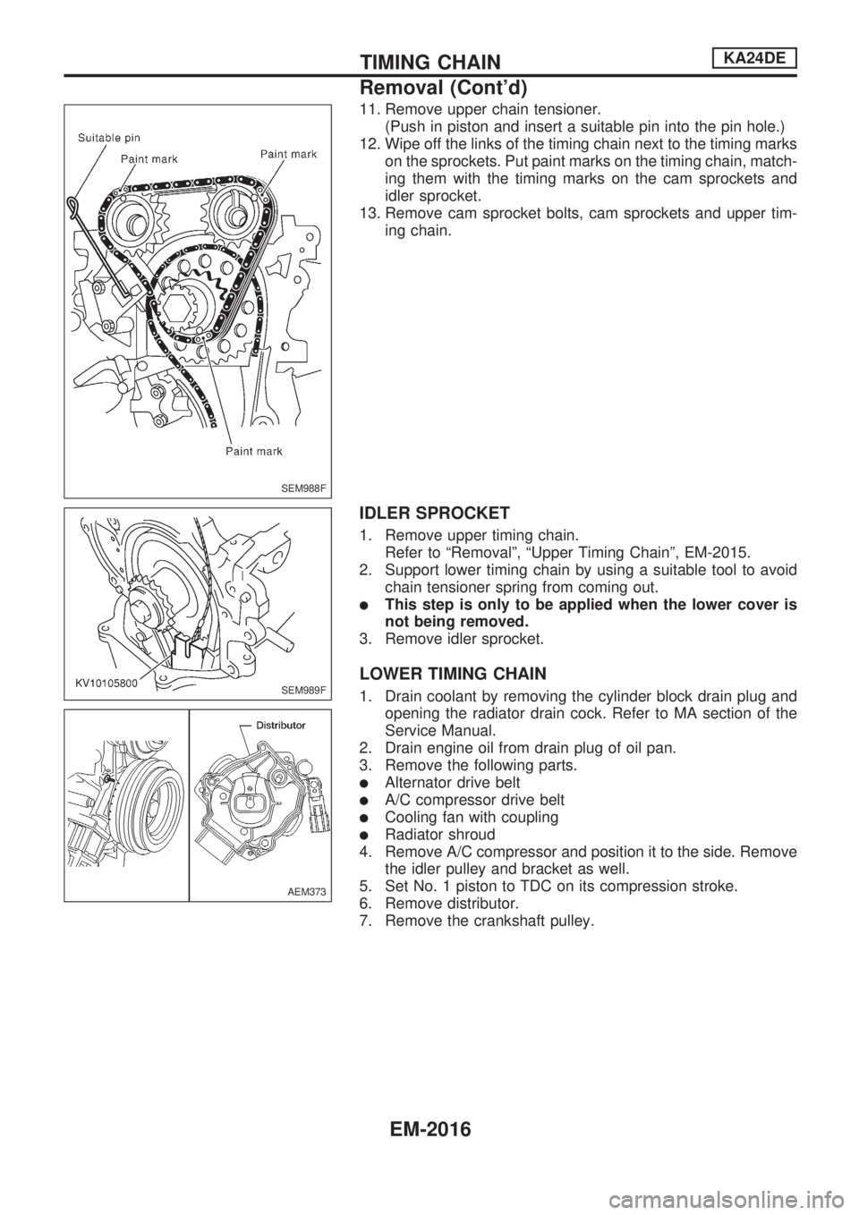
11. Remove upper chain tensioner.
(Push in piston and insert a suitable pin into the pin hole.)
12. Wipe off the links of the timing chain next to the timing marks
on the sprockets. Put paint marks on the timing chain, match-
ing them with the timing marks on the cam sprockets and
idler sprocket.
13. Remove cam sprocket bolts, cam sprockets and upper tim-
ing chain.
IDLER SPROCKET
1. Remove upper timing chain.
Refer to ªRemovalº, ªUpper Timing Chainº, EM-2015.
2. Support lower timing chain by using a suitable tool to avoid
chain tensioner spring from coming out.
lThis step is only to be applied when the lower cover is
not being removed.
3. Remove idler sprocket.
LOWER TIMING CHAIN
1. Drain coolant by removing the cylinder block drain plug and
opening the radiator drain cock. Refer to MA section of the
Service Manual.
2. Drain engine oil from drain plug of oil pan.
3. Remove the following parts.
lAlternator drive belt
lA/C compressor drive belt
lCooling fan with coupling
lRadiator shroud
4. Remove A/C compressor and position it to the side. Remove
the idler pulley and bracket as well.
5. Set No. 1 piston to TDC on its compression stroke.
6. Remove distributor.
7. Remove the crankshaft pulley.
SEM988F
SEM989F
AEM373
TIMING CHAINKA24DE
Removal (Cont'd)
EM-2016
Page 464 of 666
WARNING:
lPosition vehicle on a flat and solid surface.
lPlace chocks at front and back of rear wheels.
lDo not remove engine until exhaust system has com-
pletely cooled off.
Otherwise, you may burn yourself and/or fire may break
out in fuel line.
lBefore disconnecting fuel hose, release fuel pressure.
Refer to EC section (ªFuel Pressure Releaseº, ªBASIC
SERVICE PROCEDUREº).
lBe sure to hoist engine and transmission in a safe man-
ner.
lFor engines not equipped with engine slingers, attach
proper slingers and bolts described in PARTS CATA-
LOG.
CAUTION:
lWhen lifting engine, be sure to clear surrounding parts.
Take special care near accelerator wire casing, brake
lines and brake master cylinder.
lIn hoisting the engine, always use engine slingers in a
safe manner.
lFor 4WD models, apply sealant between engine and
transmission. Refer to MT section (ªRemoval and Instal-
lationº).
Removal
1. Drain coolant from engine block and radiator. Refer to MA
section (ªChanging Engine Coolantº, ªENGINE MAINTE-
NANCEº).
2. Release fuel pressure. Refer to EC section (ªFuel Pressure
Releaseº, ªBASIC SERVICE PROCEDUREº).
3. Remove negative battery cable.
4. Remove hood. Refer to BT section.
5. Remove air cleaner and air duct.
6. Remove power steering drive belt, alternator drive belt and
A/C compressor drive belt.
7. Remove radiator. Refer to LC section (ªRadiatorº, ªENGINE
COOLING SYSTEMº).
8. Remove exhaust manifold heat shield.
9. Disconnect exhaust system from exhaust manifold.
10. Remove A/C compressor from bracket. Refer to HA section
(ªCompressor Mountingº, ªSERVICE PROCEDURESº).
11. Disconnect accelerator wire, vacuum hoses, electrical
connectors, heater hoses and vacuum booster hose.
ENGINE REMOVALKA24DE
EM-2036