1999 NISSAN PICK-UP water
[x] Cancel search: waterPage 137 of 666
Unified Control Meter System Description
UNIFIED CONTROL METER
Speedometer, odo/trip meter, tachometer, fuel gauge and water
temperature gauge are controlled totally by unified meter control
unit.
Meter/gauge Operation and Odo/Trip Meter
Segment Check in Diagnosis Mode
DIAGNOSIS FUNCTION
lOdo/trip meter segment can be checked in diagnosis mode.
lMeters/gauges can be checked in diagnosis mode.
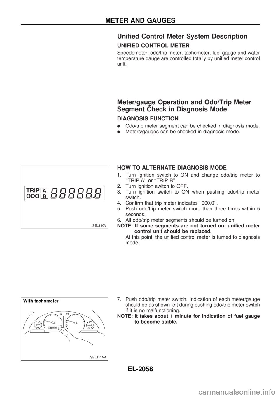
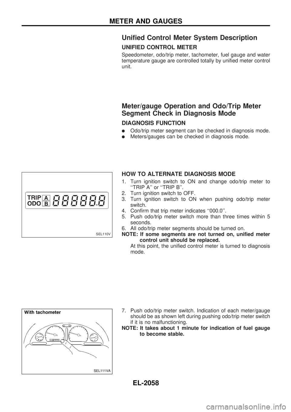
HOW TO ALTERNATE DIAGNOSIS MODE
1. Turn ignition switch to ON and change odo/trip meter to
``TRIP A'' or ``TRIP B''.
2. Turn ignition switch to OFF.
3. Turn ignition switch to ON when pushing odo/trip meter
switch.
4. Confirm that trip meter indicates ``000.0''.
5. Push odo/trip meter switch more than three times within 5
seconds.
6. All odo/trip meter segments should be turned on.
NOTE: If some segments are not turned on, unified meter
control unit should be replaced.
At this point, the unified control meter is turned to diagnosis
mode.
7. Push odo/trip meter switch. Indication of each meter/gauge
should be as shown left during pushing odo/trip meter switch
if it is no malfunctioning.
NOTE: It takes about 1 minute for indication of fuel gauge
to become stable.
SEL110V
SEL111VA
METER AND GAUGES
EL-2058
Page 138 of 666
Flexible Print Circuit (FPC) (Models with
Tachometer)
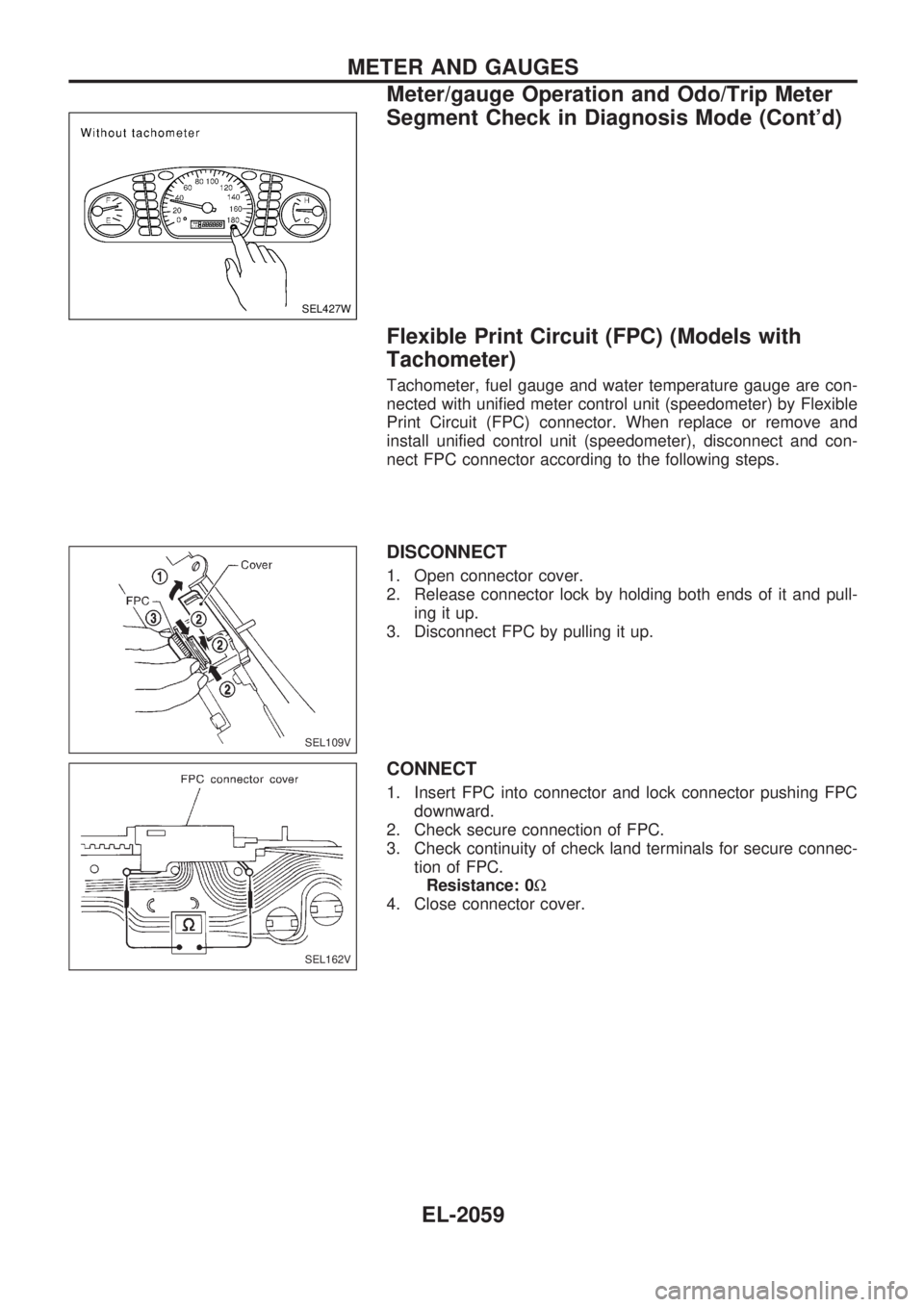
Tachometer, fuel gauge and water temperature gauge are con-
nected with unified meter control unit (speedometer) by Flexible
Print Circuit (FPC) connector. When replace or remove and
install unified control unit (speedometer), disconnect and con-
nect FPC connector according to the following steps.
DISCONNECT
1. Open connector cover.
2. Release connector lock by holding both ends of it and pull-
ing it up.
3. Disconnect FPC by pulling it up.
CONNECT
1. Insert FPC into connector and lock connector pushing FPC
downward.
2. Check secure connection of FPC.
3. Check continuity of check land terminals for secure connec-
tion of FPC.
Resistance: 0W
4. Close connector cover.
SEL427W
SEL109V
SEL162V
METER AND GAUGES
Meter/gauge Operation and Odo/Trip Meter
Segment Check in Diagnosis Mode (Cont'd)
EL-2059
Page 140 of 666
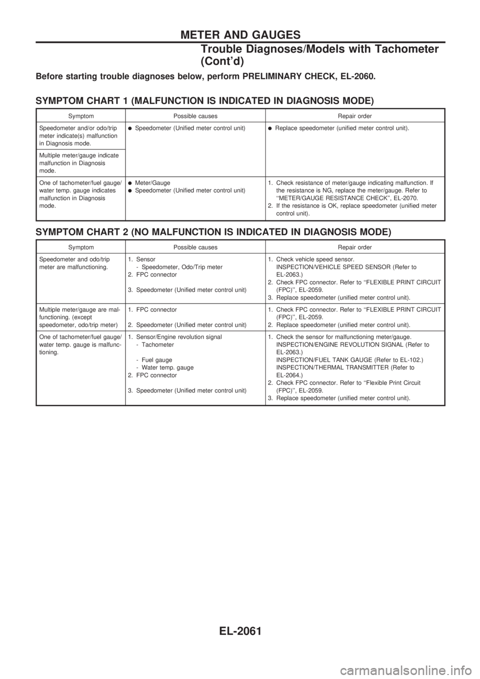
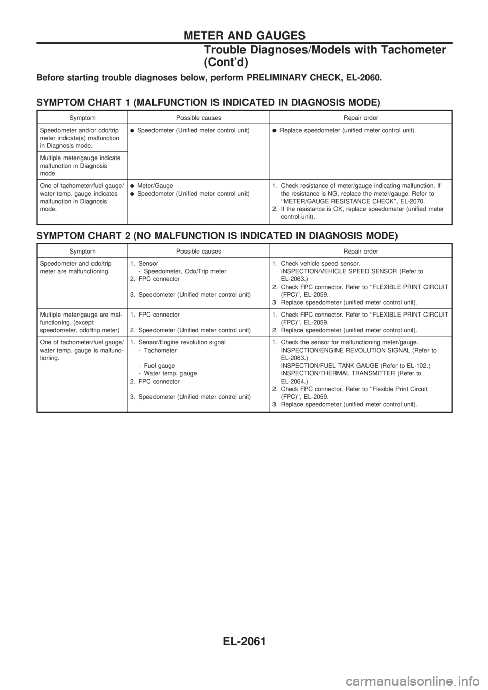
Before starting trouble diagnoses below, perform PRELIMINARY CHECK, EL-2060.
SYMPTOM CHART 1 (MALFUNCTION IS INDICATED IN DIAGNOSIS MODE)
Symptom Possible causes Repair order
Speedometer and/or odo/trip
meter indicate(s) malfunction
in Diagnosis mode.
lSpeedometer (Unified meter control unit)lReplace speedometer (unified meter control unit).
Multiple meter/gauge indicate
malfunction in Diagnosis
mode.
One of tachometer/fuel gauge/
water temp. gauge indicates
malfunction in Diagnosis
mode.
lMeter/GaugelSpeedometer (Unified meter control unit)1. Check resistance of meter/gauge indicating malfunction. If
the resistance is NG, replace the meter/gauge. Refer to
``METER/GAUGE RESISTANCE CHECK'', EL-2070.
2. If the resistance is OK, replace speedometer (unified meter
control unit).
SYMPTOM CHART 2 (NO MALFUNCTION IS INDICATED IN DIAGNOSIS MODE)
Symptom Possible causes Repair order
Speedometer and odo/trip
meter are malfunctioning.1. Sensor
- Speedometer, Odo/Trip meter
2. FPC connector
3. Speedometer (Unified meter control unit)1. Check vehicle speed sensor.
INSPECTION/VEHICLE SPEED SENSOR (Refer to
EL-2063.)
2. Check FPC connector. Refer to ``FLEXIBLE PRINT CIRCUIT
(FPC)'', EL-2059.
3. Replace speedometer (unified meter control unit).
Multiple meter/gauge are mal-
functioning. (except
speedometer, odo/trip meter)1. FPC connector
2. Speedometer (Unified meter control unit)1. Check FPC connector. Refer to ``FLEXIBLE PRINT CIRCUIT
(FPC)'', EL-2059.
2. Replace speedometer (unified meter control unit).
One of tachometer/fuel gauge/
water temp. gauge is malfunc-
tioning.1. Sensor/Engine revolution signal
- Tachometer
- Fuel gauge
- Water temp. gauge
2. FPC connector
3. Speedometer (Unified meter control unit)1. Check the sensor for malfunctioning meter/gauge.
INSPECTION/ENGINE REVOLUTION SIGNAL (Refer to
EL-2063.)
INSPECTION/FUEL TANK GAUGE (Refer to EL-102.)
INSPECTION/THERMAL TRANSMITTER (Refer to
EL-2064.)
2. Check FPC connector. Refer to ``Flexible Print Circuit
(FPC)'', EL-2059.
3. Replace speedometer (unified meter control unit).
METER AND GAUGES
Trouble Diagnoses/Models with Tachometer
(Cont'd)
EL-2061
Page 145 of 666
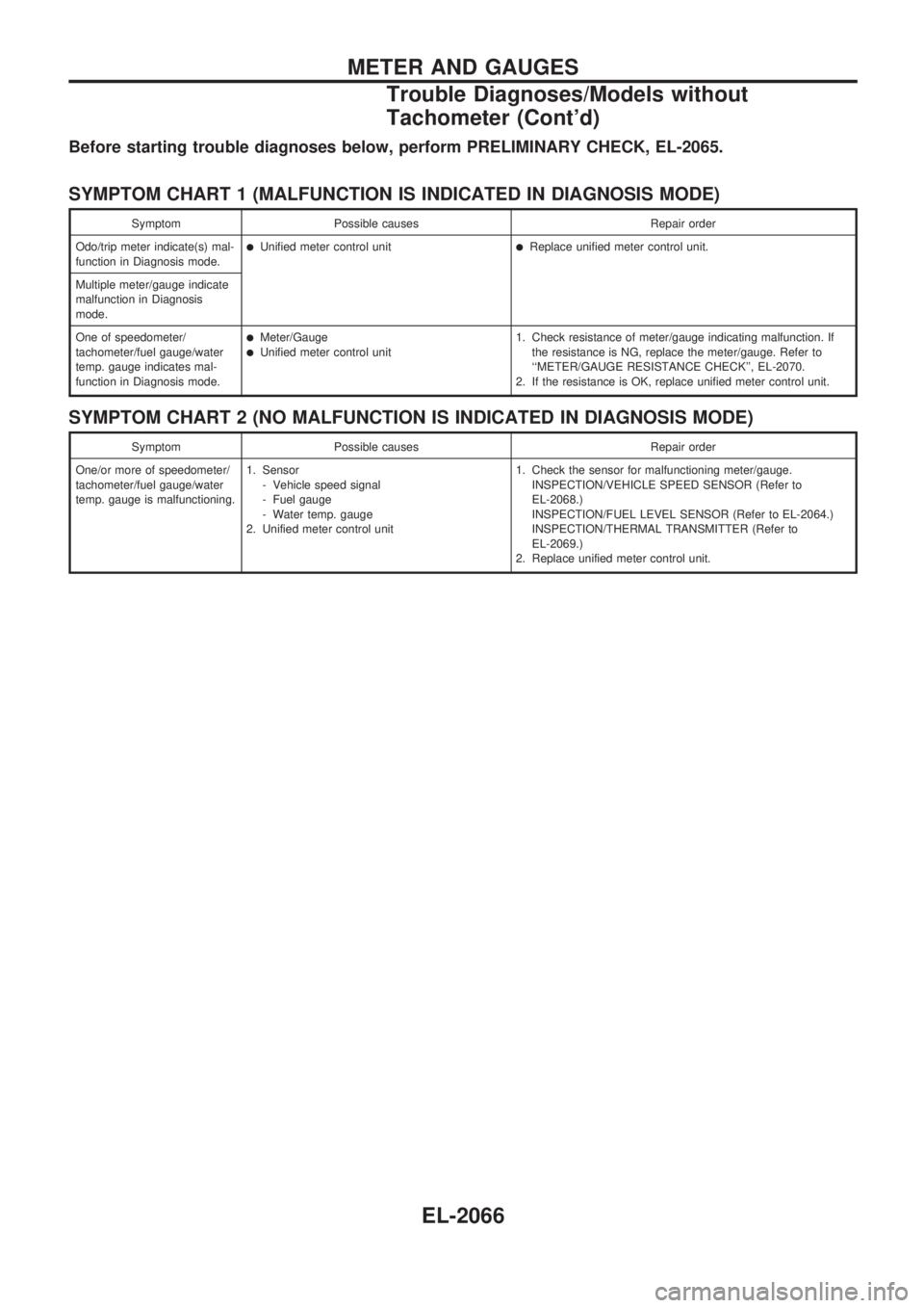
Before starting trouble diagnoses below, perform PRELIMINARY CHECK, EL-2065.
SYMPTOM CHART 1 (MALFUNCTION IS INDICATED IN DIAGNOSIS MODE)
Symptom Possible causes Repair order
Odo/trip meter indicate(s) mal-
function in Diagnosis mode.
lUnified meter control unitlReplace unified meter control unit.
Multiple meter/gauge indicate
malfunction in Diagnosis
mode.
One of speedometer/
tachometer/fuel gauge/water
temp. gauge indicates mal-
function in Diagnosis mode.
lMeter/GaugelUnified meter control unit1. Check resistance of meter/gauge indicating malfunction. If
the resistance is NG, replace the meter/gauge. Refer to
``METER/GAUGE RESISTANCE CHECK'', EL-2070.
2. If the resistance is OK, replace unified meter control unit.
SYMPTOM CHART 2 (NO MALFUNCTION IS INDICATED IN DIAGNOSIS MODE)
Symptom Possible causes Repair order
One/or more of speedometer/
tachometer/fuel gauge/water
temp. gauge is malfunctioning.1. Sensor
- Vehicle speed signal
- Fuel gauge
- Water temp. gauge
2. Unified meter control unit1. Check the sensor for malfunctioning meter/gauge.
INSPECTION/VEHICLE SPEED SENSOR (Refer to
EL-2068.)
INSPECTION/FUEL LEVEL SENSOR (Refer to EL-2064.)
INSPECTION/THERMAL TRANSMITTER (Refer to
EL-2069.)
2. Replace unified meter control unit.
METER AND GAUGES
Trouble Diagnoses/Models without
Tachometer (Cont'd)
EL-2066
Page 150 of 666

THERMAL TRANSMITTER CHECK
Check the resistance between the terminals of thermal transmit-
ter and body ground.
Water temperature Resistance
60ÉC (140ÉF) Approx. 167 - 211W
100ÉC (212ÉF) Approx. 47 - 53W
VEHICLE SPEED SENSOR SIGNAL CHECK
1. Remove vehicle speed sensor from transmission.
2. Turn vehicle speed sensor pinion quickly and measure volt-
age between terminals
VaandVb.
MEL424F
SEL378PA
METER AND GAUGES
Electrical Components Inspection (Cont'd)
EL-2071
Page 309 of 666
Unified Control Meter System Description
UNIFIED CONTROL METER
Speedometer, odo/trip meter, tachometer, fuel gauge and water
temperature gauge are controlled totally by unified meter control
unit.
Meter/gauge Operation and Odo/Trip Meter
Segment Check in Diagnosis Mode
DIAGNOSIS FUNCTION
lOdo/trip meter segment can be checked in diagnosis mode.
lMeters/gauges can be checked in diagnosis mode.
HOW TO ALTERNATE DIAGNOSIS MODE
1. Turn ignition switch to ON and change odo/trip meter to
``TRIP A'' or ``TRIP B''.
2. Turn ignition switch to OFF.
3. Turn ignition switch to ON when pushing odo/trip meter
switch.
4. Confirm that trip meter indicates ``000.0''.
5. Push odo/trip meter switch more than three times within 5
seconds.
6. All odo/trip meter segments should be turned on.
NOTE: If some segments are not turned on, unified meter
control unit should be replaced.
At this point, the unified control meter is turned to diagnosis
mode.
7. Push odo/trip meter switch. Indication of each meter/gauge
should be as shown left during pushing odo/trip meter switch
if it is no malfunctioning.
NOTE: It takes about 1 minute for indication of fuel gauge
to become stable.
SEL110V
SEL111VA
METER AND GAUGES
EL-2058
Page 310 of 666

Flexible Print Circuit (FPC) (Models with
Tachometer)
Tachometer, fuel gauge and water temperature gauge are con-
nected with unified meter control unit (speedometer) by Flexible
Print Circuit (FPC) connector. When replace or remove and
install unified control unit (speedometer), disconnect and con-
nect FPC connector according to the following steps.
DISCONNECT
1. Open connector cover.
2. Release connector lock by holding both ends of it and pull-
ing it up.
3. Disconnect FPC by pulling it up.
CONNECT
1. Insert FPC into connector and lock connector pushing FPC
downward.
2. Check secure connection of FPC.
3. Check continuity of check land terminals for secure connec-
tion of FPC.
Resistance: 0W
4. Close connector cover.
SEL427W
SEL109V
SEL162V
METER AND GAUGES
Meter/gauge Operation and Odo/Trip Meter
Segment Check in Diagnosis Mode (Cont'd)
EL-2059
Page 312 of 666
Before starting trouble diagnoses below, perform PRELIMINARY CHECK, EL-2060.
SYMPTOM CHART 1 (MALFUNCTION IS INDICATED IN DIAGNOSIS MODE)
Symptom Possible causes Repair order
Speedometer and/or odo/trip
meter indicate(s) malfunction
in Diagnosis mode.
lSpeedometer (Unified meter control unit)lReplace speedometer (unified meter control unit).
Multiple meter/gauge indicate
malfunction in Diagnosis
mode.
One of tachometer/fuel gauge/
water temp. gauge indicates
malfunction in Diagnosis
mode.
lMeter/GaugelSpeedometer (Unified meter control unit)1. Check resistance of meter/gauge indicating malfunction. If
the resistance is NG, replace the meter/gauge. Refer to
``METER/GAUGE RESISTANCE CHECK'', EL-2070.
2. If the resistance is OK, replace speedometer (unified meter
control unit).
SYMPTOM CHART 2 (NO MALFUNCTION IS INDICATED IN DIAGNOSIS MODE)
Symptom Possible causes Repair order
Speedometer and odo/trip
meter are malfunctioning.1. Sensor
- Speedometer, Odo/Trip meter
2. FPC connector
3. Speedometer (Unified meter control unit)1. Check vehicle speed sensor.
INSPECTION/VEHICLE SPEED SENSOR (Refer to
EL-2063.)
2. Check FPC connector. Refer to ``FLEXIBLE PRINT CIRCUIT
(FPC)'', EL-2059.
3. Replace speedometer (unified meter control unit).
Multiple meter/gauge are mal-
functioning. (except
speedometer, odo/trip meter)1. FPC connector
2. Speedometer (Unified meter control unit)1. Check FPC connector. Refer to ``FLEXIBLE PRINT CIRCUIT
(FPC)'', EL-2059.
2. Replace speedometer (unified meter control unit).
One of tachometer/fuel gauge/
water temp. gauge is malfunc-
tioning.1. Sensor/Engine revolution signal
- Tachometer
- Fuel gauge
- Water temp. gauge
2. FPC connector
3. Speedometer (Unified meter control unit)1. Check the sensor for malfunctioning meter/gauge.
INSPECTION/ENGINE REVOLUTION SIGNAL (Refer to
EL-2063.)
INSPECTION/FUEL TANK GAUGE (Refer to EL-102.)
INSPECTION/THERMAL TRANSMITTER (Refer to
EL-2064.)
2. Check FPC connector. Refer to ``Flexible Print Circuit
(FPC)'', EL-2059.
3. Replace speedometer (unified meter control unit).
METER AND GAUGES
Trouble Diagnoses/Models with Tachometer
(Cont'd)
EL-2061