1999 NISSAN PICK-UP lock
[x] Cancel search: lockPage 40 of 666
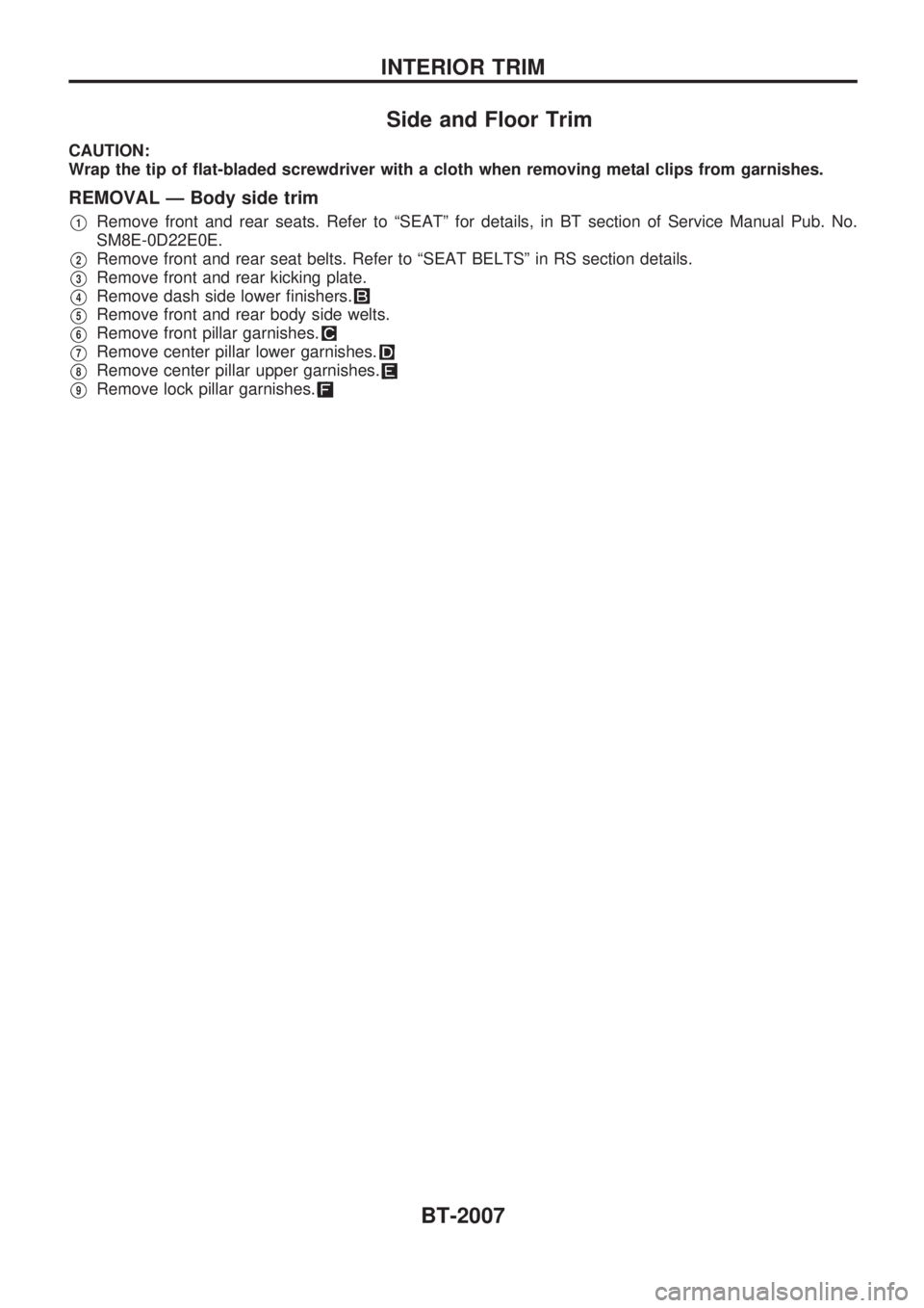
Side and Floor Trim
CAUTION:
Wrap the tip of flat-bladed screwdriver with a cloth when removing metal clips from garnishes.
REMOVAL Ð Body side trim
V1Remove front and rear seats. Refer to ªSEATº for details, in BT section of Service Manual Pub. No.
SM8E-0D22E0E.
V2Remove front and rear seat belts. Refer to ªSEAT BELTSº in RS section details.
V3Remove front and rear kicking plate.
V4Remove dash side lower finishers.
V5Remove front and rear body side welts.
V6Remove front pillar garnishes.
V7Remove center pillar lower garnishes.
V8Remove center pillar upper garnishes.
V9Remove lock pillar garnishes.
INTERIOR TRIM
BT-2007
Page 81 of 666
WARNING LAMPS.............................................. 2072
Schematic ........................................................ 2072
Wiring Diagram - WARN -/Gasoline Engine.... 2073
Wiring Diagram - WARN -/Diesel Engine ........ 2078
Electrical Components Inspection ................... 2083
Wiring Diagram - CHIME -/LHD Models.......... 2084
Wiring Diagram - CHIME -/RHD Models ......... 2085
FRONT WIPER AND WASHER.......................... 2086
Wiring Diagram - WIPER -/LHD Models with
Intermittent ....................................................... 2086
Wiring Diagram - WIPER -/LHD Models
without Intermittent........................................... 2087
Wiring Diagram - WIPER -/RHD M/T Models
with Intermittent................................................ 2088
Wiring Diagram - WIPER -/RHD Models
without Intermittent........................................... 2090
HEADLAMP WASHER........................................ 2092
Wiring Diagram - HLC - ................................... 2092
HORN................................................................... 2093
Wiring Diagram - HORN -................................ 2093
CIGARETTE LIGHTER........................................ 2094
Wiring Diagram - CIGAR - ............................... 2094
CLOCK................................................................. 2095
Wiring Diagram - CLOCK - .............................. 2095
REAR WINDOW DEFOGGER AND MIRROR
DEFOGGER......................................................... 2096
Wiring Diagram - DEF -/LHD Models .............. 2096
Wiring Diagram - DEF -/RHD Models ............. 2097
Electrical Components Inspection ................... 2098
AUDIO.................................................................. 2099
Wiring Diagram - AUDIO -/LHD Models
Type-2 .............................................................. 2099
Wiring Diagram - AUDIO -/LHD Models
Type-3 .............................................................. 2100
Wiring Diagram - AUDIO -/RHD Models ......... 2102
AUDIO ANTENNA............................................... 2103
Power Antenna/Wiring Diagram - P/ANT - ...... 2103
POWER DOOR MIRROR.................................... 2104
Wiring Diagram - MIRROR -/LHD Models....... 2104
Wiring Diagram - MIRROR -/RHD Models ...... 2105
HEATED SEAT.................................................... 2106
Wiring Diagram - H/SEAT - ............................. 2106
POWER WINDOW............................................... 2108
Schematic/Without Interruption Detection
Function ........................................................... 2108Wiring Diagram - WINDOW -/Without
Interruption Detection Function........................ 2109
Trouble Diagnoses/Without Interruption
Detection Function ........................................... 2113
System Description/With Interruption Detection
Function ........................................................... 2114
Schematic/With Interruption Detection
Function ........................................................... 2115
Wiring Diagram - WINDOW -/With Interruption
Detection Function ........................................... 2116
Trouble Diagnoses/With Interruption Detection
Function ........................................................... 2120
POWER DOOR LOCK......................................... 2122
System Description .......................................... 2122
Wiring Diagram - D/LOCK - ............................. 2123
Trouble Diagnosis ............................................ 2125
MULTI-REMOTE CONTROL SYSTEM............... 2129
System Description .......................................... 2129
Schematic ........................................................ 2130
Wiring Diagram - MULTI - ............................... 2131
Trouble Diagnoses ........................................... 2135
ID Code Entry Procedure ................................ 2139
NATS (Nissan Anti-Theft System)/Models with
KA24E.................................................................. 2140
Wiring Diagram - NATS -................................. 2140
NATS (Nissan Anti-Theft System)/Diesel
engine.................................................................. 2141
Wiring Diagram - NATS -/LHD Models............ 2141
Wiring Diagram - NATS -/RHD Models ........... 2142
LOCATION OF ELECTRICAL UNITS................. 2143
Engine Compartment ....................................... 2143
Passenger Compartment ................................. 2144
HARNESS LAYOUT............................................ 2146
Main Harness ................................................... 2146
Engine Room Harness..................................... 2152
Engine Control Harness................................... 2160
Alternator Harness ........................................... 2164
Instrument Harness.......................................... 2165
Room Lamp Harness/LHD Models .................. 2166
Room Lamp Harness/RHD Models ................. 2167
Chassis Harness and Tail Harness ................. 2168
Front Door Harness (LH side) ......................... 2169
Front Door Harness (RH side)......................... 2170
WIRING DIAGRAM CODES (CELL CODES)..... 2171
WIRING DIAGRAM REFERENCE CHART
COOLING FAN .......................................................................................................... LC SECTION
ECCS, IGNITION SYSTEM, QUICK-GLOW SYSTEM, FUEL HEATER SYSTEM .. EC SECTION
ANTI-LOCK BRAKE SYSTEM .................................................................................. BR SECTION
SRS ``AIR BAG'' ........................................................................................................ RS SECTION
HEATER AND AIR CONDITIONER .......................................................................... HA SECTION
EL-2002
Page 138 of 666
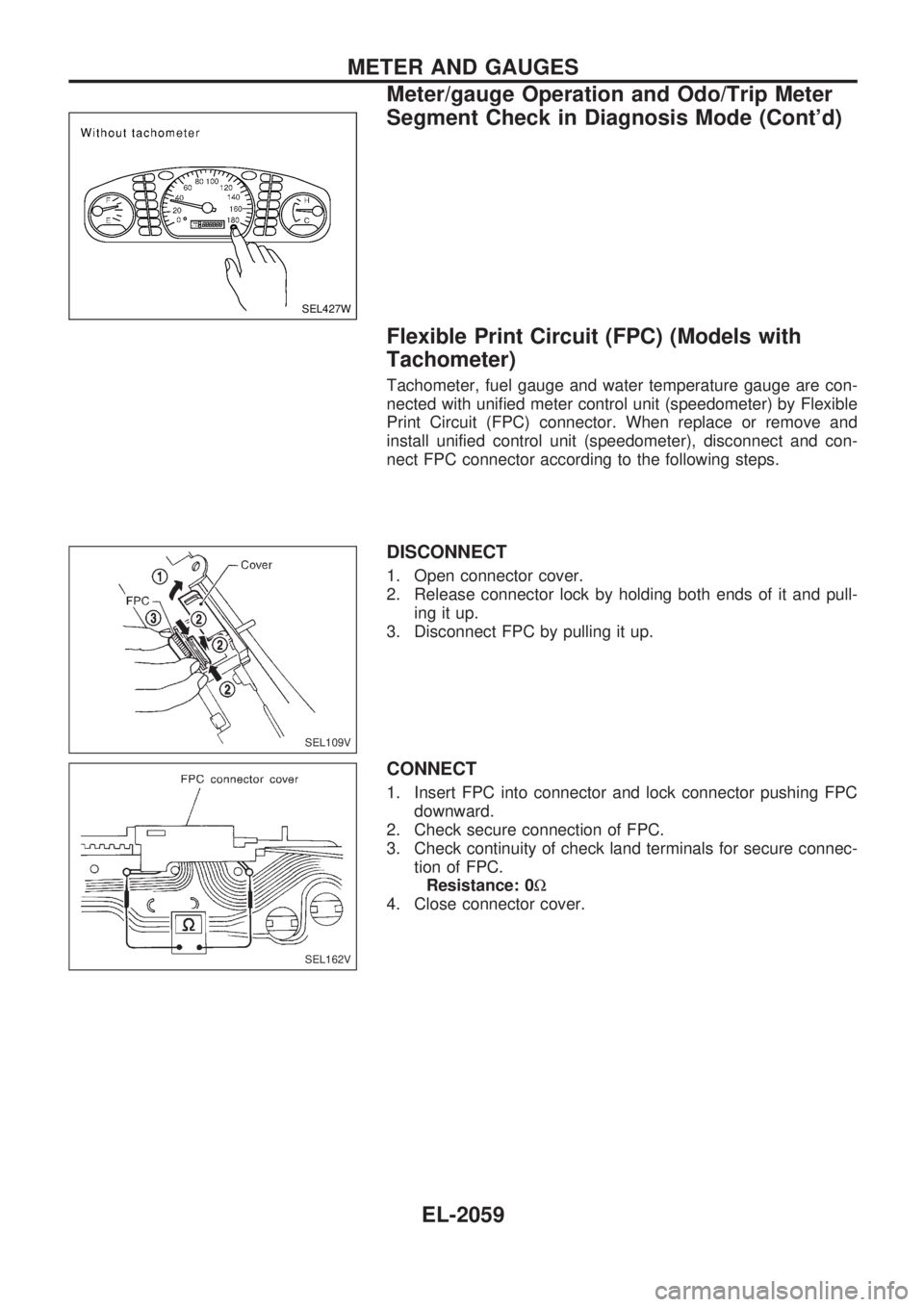
Flexible Print Circuit (FPC) (Models with
Tachometer)
Tachometer, fuel gauge and water temperature gauge are con-
nected with unified meter control unit (speedometer) by Flexible
Print Circuit (FPC) connector. When replace or remove and
install unified control unit (speedometer), disconnect and con-
nect FPC connector according to the following steps.
DISCONNECT
1. Open connector cover.
2. Release connector lock by holding both ends of it and pull-
ing it up.
3. Disconnect FPC by pulling it up.
CONNECT
1. Insert FPC into connector and lock connector pushing FPC
downward.
2. Check secure connection of FPC.
3. Check continuity of check land terminals for secure connec-
tion of FPC.
Resistance: 0W
4. Close connector cover.
SEL427W
SEL109V
SEL162V
METER AND GAUGES
Meter/gauge Operation and Odo/Trip Meter
Segment Check in Diagnosis Mode (Cont'd)
EL-2059
Page 141 of 666
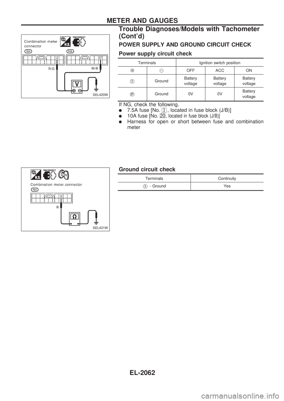
POWER SUPPLY AND GROUND CIRCUIT CHECK
Power supply circuit check
Terminals Ignition switch position
Å@OFF ACC ON
V2GroundBattery
voltageBattery
voltageBattery
voltage
V37Ground 0V 0VBattery
voltage
If NG, check the following.
l7.5A fuse [No.3, located in fuse block (J/B)]
l10A fuse [No.20 , located in fuse block (J/B)]
lHarness for open or short between fuse and combination
meter
Ground circuit check
Terminals Continuity
V3- Ground Yes
SEL420W
SEL421W
METER AND GAUGES
Trouble Diagnoses/Models with Tachometer
(Cont'd)
EL-2062
Page 146 of 666
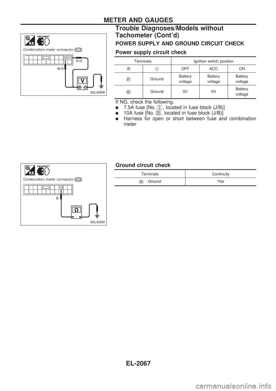
POWER SUPPLY AND GROUND CIRCUIT CHECK
Power supply circuit check
Terminals Ignition switch position
Å@OFF ACC ON
V21GroundBattery
voltageBattery
voltageBattery
voltage
V22Ground 0V 0VBattery
voltage
If NG, check the following.
l7.5A fuse [No.3, located in fuse block (J/B)]
l10A fuse [No.20, located in fuse block (J/B)]
lHarness for open or short between fuse and combination
meter
Ground circuit check
Terminals Continuity
V23- Ground Yes
SEL428W
SEL429W
METER AND GAUGES
Trouble Diagnoses/Models without
Tachometer (Cont'd)
EL-2067
Page 174 of 666
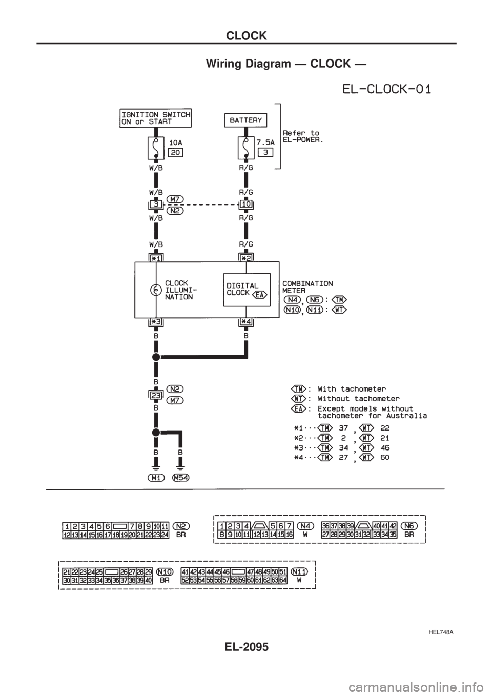
Wiring Diagram Ð CLOCK Ð
HEL748A
CLOCK
EL-2095
Page 192 of 666
Trouble Diagnoses/Without Interruption
Detection Function
Symptom Possible cause Repair order
None of the power windows can be
operated using any switch.1. 30A fusible link and circuit
breaker-1
2. Grounds
M1andM54
3. Power window relay
4. Open/short in power window
main switch circuit1. Check 30A fusible link (letter
b, located in fusible
link and fuse box) and circuit breaker-1, located in
fuse block. Turn ignition switch ``ON'' and verify bat-
tery positive voltage is present at terminal
V1of
power window main switch and terminal
V5of sub-
switch.
2. Check grounds
M1andM54.
3. Check power window relay.
4. Check harness between power window relay and
power window main switch for open/short circuit.
Driver side power window cannot
be operated but other windows can
be operated.1. Driver side power window regu-
lator circuit
2. Driver side power window regu-
lator1. Check harness between power window main switch
and power window regulator for open or short circuit.
2. Check driver side power window regulator.
One or some of power window
except driver side power window
cannot be operated.1. Power window sub-switch
2. Passenger side power window
regulator
3. Power window main switch
4. Power window circuit1. Check power window sub-switch.
2. Check power window regulator of malfunctioning
power window.
3. Check power window main switch.
4-1. Check harnesses between power window main
switch and power window sub-switch for open/short
circuit.
4-2. Check harnesses between power window sub-
switch and power window regulator for open/short
circuit.
Passenger power window cannot
be operated using power window
main switch but can be operated by
power window sub-switch.1. Power window main switch 1. Check power window main switch.
Driver side power window auto
function cannot be operated using
power window main switch.1. Power window main switch 1. Check power window main switch.
POWER WINDOW
EL-2113
Page 193 of 666
System Description/With Interruption
Detection Function
OUTLINE
Power window system consists of
lCPU (combined with power window main switch)
lfour power window regulators
When ignition switch is in the ``ON'' position, power window can be operated depending on power window
sub/main switch condition.
OPERATIVE CONDITION
lPower windows can be raised or lowered with each sub-switch or the power window main switch located
on the driver's door trim when ignition switch is in the ``ON'' position and power window lock switch on
the driver's door trim is unlocked.
lWhen power window lock switch is locked, no windows can be raised or lowered except for driver's side
window.
lWhen ignition switch is in the ``ON'' position, to fully open/close the driver's side window, press down/
pull up completely on the automatic switch (main switch) and release it; it needs not be held. The win-
dow will automatically open/close all the way. To stop the window, pull up/press down then release the
switch.
lAfter turning ignition switch to OFF, the driver's side window can be raised or lowered for 15 minutes.
The timer control for supplying power after turning ignition switch to ``OFF'' will be canceled when the
driver's side door is closed. (Except models for Europe)
INTERRUPTION DETECTION FUNCTION
CPU (combined with power window main switch) monitors the power window regulator motor operation and
the power window position (full closed or other) for driver's power window by the signals from encoder and
limit switch in front power window regulator (driver's side).
When CPU (combined with power window main switch) detects interruption during the following close
operation in the driver's side door,
lautomatic close operation when ignition switch is in the ``ON'' position
lautomatic close operation during power window timer operation
lmanual close operation during power window timer operation
CPU (combined with power window main switch) controls driver's power window regulator motor for open
and the power window will be lowered about 150 mm (5.91 in).
POWER WINDOW
EL-2114