1999 NISSAN PICK-UP engine control
[x] Cancel search: engine controlPage 1 of 666
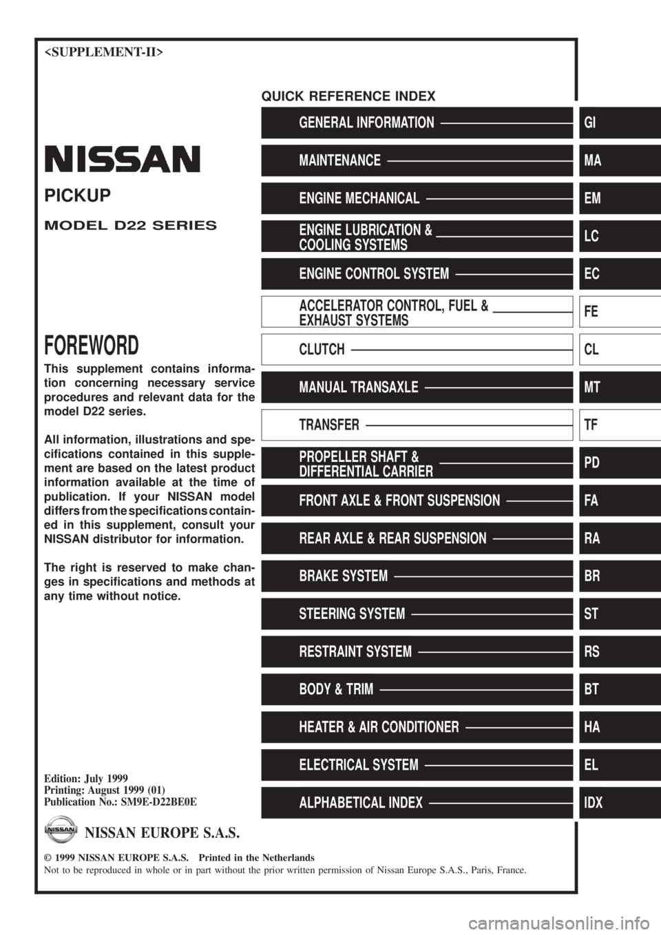
GENERAL INFORMATIONGI
MAINTENANCEMA
ENGINE MECHANICALEM
ENGINE LUBRICATION &
COOLING SYSTEMSLC
ENGINE CONTROL SYSTEMEC
ACCELERATOR CONTROL, FUEL &
EXHAUST SYSTEMSFE
CLUTCHCL
MANUAL TRANSAXLEMT
TRANSFERTF
PROPELLER SHAFT &
DIFFERENTIAL CARRIERPD
FRONT AXLE & FRONT SUSPENSIONFA
REAR AXLE & REAR SUSPENSIONRA
BRAKE SYSTEMBR
STEERING SYSTEMST
RESTRAINT SYSTEMRS
BODY & TRIMBT
HEATER & AIR CONDITIONERHA
ELECTRICAL SYSTEMEL
ALPHABETICAL INDEXIDX
PICKUP
MODEL D22 SERIES
FOREWORD
This supplement contains informa-
tion concerning necessary service
procedures and relevant data for the
model D22 series.
All information, illustrations and spe-
ci®cations contained in this supple-
ment are based on the latest product
information available at the time of
publication. If your NISSAN model
differs from the speci®cations contain-
ed in this supplement, consult your
NISSAN distributor for information.
The right is reserved to make chan-
ges in speci®cations and methods at
any time without notice.
Edition: July 1999
Printing: August 1999 (01)
Publication No.: SM9E-D22BE0E
NISSAN EUROPE S.A.S.
1999 NISSAN EUROPE S.A.S. Printed in the Netherlands
Not to be reproduced in whole or in part without the prior written permission of Nissan Europe S.A.S., Paris, France.
QUICK REFERENCE INDEX
Page 46 of 666
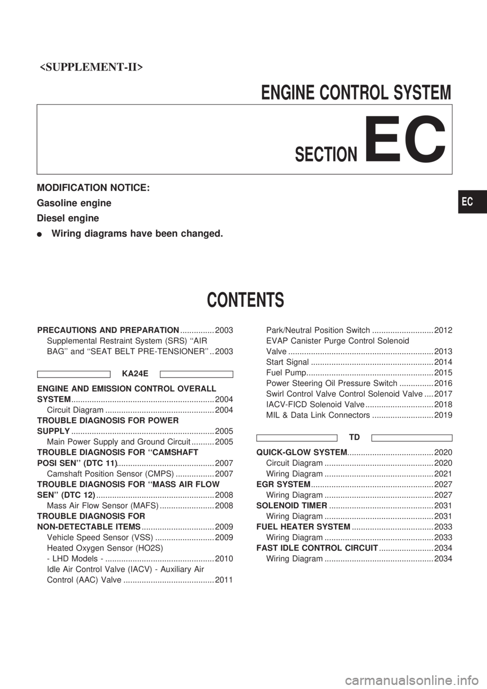
ENGINECONTROLSYSTEM
SECTION
EC
MODIFICATION NOTICE:
Gasoline engine
Diesel engine
lWiring diagrams have been changed.
CONTENTS
PRECAUTIONS AND PREPARATION ............... 2003
Supplemental Restraint System (SRS) ``AIR
BAG'' and ``SEAT BELT PRE-TENSIONER'' .. 2003
KA24E
ENGINE AND EMISSION CONTROL OVERALL
SYSTEM............................................................... 2004
Circuit Diagram ................................................ 2004
TROUBLE DIAGNOSIS FOR POWER
SUPPLY ............................................................... 2005
Main Power Supply and Ground Circuit .......... 2005
TROUBLE DIAGNOSIS FOR ``CAMSHAFT
POSI SEN'' (DTC 11) ........................................... 2007
Camshaft Position Sensor (CMPS) ................. 2007
TROUBLE DIAGNOSIS FOR ``MASS AIR FLOW
SEN'' (DTC 12) .................................................... 2008
Mass Air Flow Sensor (MAFS) ........................ 2008
TROUBLE DIAGNOSIS FOR
NON-DETECTABLE ITEMS ................................ 2009
Vehicle Speed Sensor (VSS) .......................... 2009
Heated Oxygen Sensor (HO2S)
- LHD Models - ................................................ 2010
Idle Air Control Valve (IACV) - Auxiliary Air
Control (AAC) Valve ........................................ 2011 Park/Neutral Position Switch ........................... 2012
EVAP Canister Purge Control Solenoid
Valve ................................................................ 2013
Start Signal ...................................................... 2014
Fuel Pump........................................................ 2015
Power Steering Oil Pressure Switch ............... 2016
Swirl Control Valve Control Solenoid Valve .... 2017
IACV-FICD Solenoid Valve .............................. 2018
MIL & Data Link Connectors ........................... 2019
TD
QUICK-GLOW SYSTEM ...................................... 2020
Circuit Diagram ................................................ 2020
Wiring Diagram ................................................ 2021
EGR SYSTEM ...................................................... 2027
Wiring Diagram ................................................ 2027
SOLENOID TIMER .............................................. 2031
Wiring Diagram ................................................ 2031
FUEL HEATER SYSTEM .................................... 2033
Wiring Diagram ................................................ 2033
FAST IDLE CONTROL CIRCUIT ........................ 2034
Wiring Diagram ................................................ 2034
EC
Page 49 of 666

Circuit Diagram
HEC631
ENGINE AND EMISSION CONTROL OVERALL SYSTEMKA24E
EC-2004
Page 79 of 666

Wiring Diagram
TD25 AND TD25Ti ENGINES
HEC722
FAST IDLE CONTROL CIRCUITTD
EC-2034
Page 80 of 666
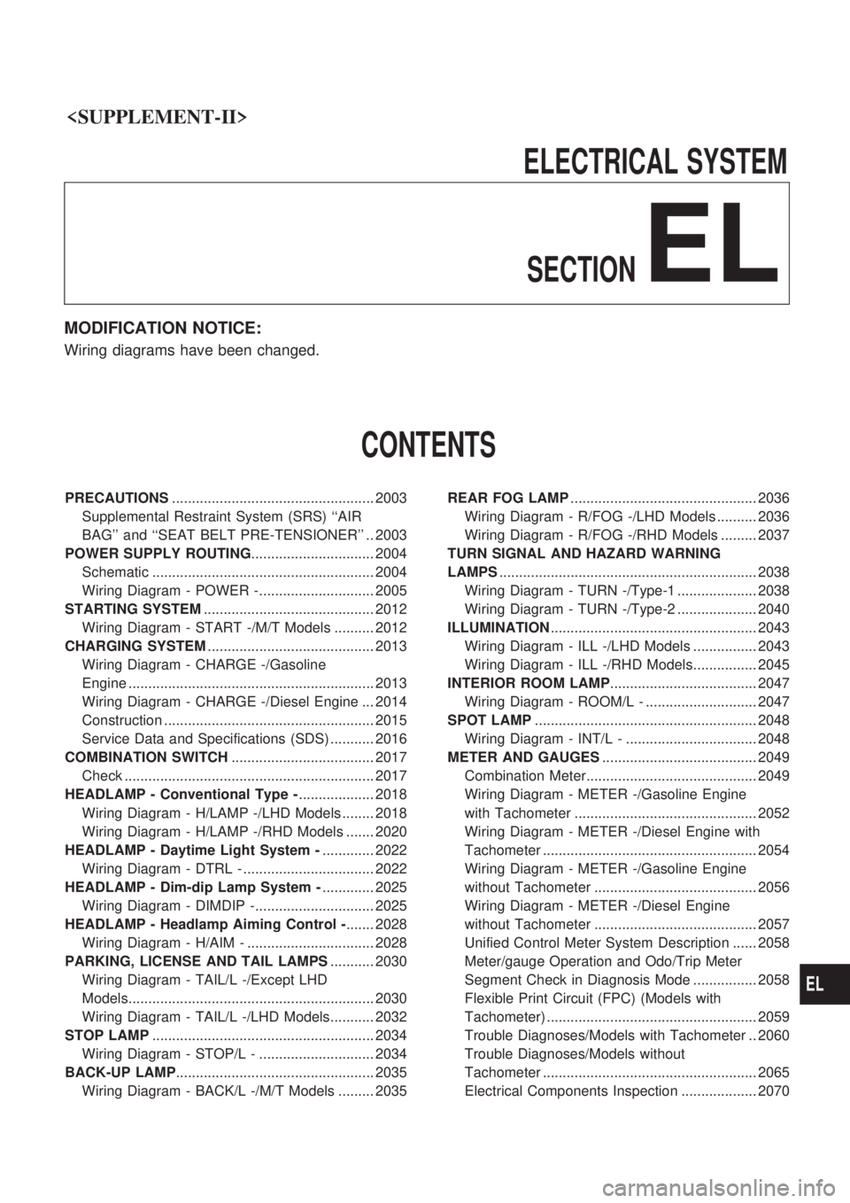
ELECTRICALSYSTEM
SECTION
EL
MODIFICATION NOTICE:
Wiring diagrams have been changed.
CONTENTS
PRECAUTIONS ................................................... 2003
Supplemental Restraint System (SRS) ``AIR
BAG'' and ``SEAT BELT PRE-TENSIONER'' .. 2003
POWER SUPPLY ROUTING ............................... 2004
Schematic ........................................................ 2004
Wiring Diagram - POWER -............................. 2005
STARTING SYSTEM ........................................... 2012
Wiring Diagram - START -/M/T Models .......... 2012
CHARGING SYSTEM .......................................... 2013
Wiring Diagram - CHARGE -/Gasoline
Engine .............................................................. 2013
Wiring Diagram - CHARGE -/Diesel Engine ... 2014
Construction ..................................................... 2015
Service Data and Specifications (SDS) ........... 2016
COMBINATION SWITCH .................................... 2017
Check ............................................................... 2017
HEADLAMP - Conventional Type - ................... 2018
Wiring Diagram - H/LAMP -/LHD Models ........ 2018
Wiring Diagram - H/LAMP -/RHD Models ....... 2020
HEADLAMP - Daytime Light System - ............. 2022
Wiring Diagram - DTRL - ................................. 2022
HEADLAMP - Dim-dip Lamp System - ............. 2025
Wiring Diagram - DIMDIP -.............................. 2025
HEADLAMP - Headlamp Aiming Control - ....... 2028
Wiring Diagram - H/AIM - ................................ 2028
PARKING, LICENSE AND TAIL LAMPS ........... 2030
Wiring Diagram - TAIL/L -/Except LHD
Models.............................................................. 2030
Wiring Diagram - TAIL/L -/LHD Models........... 2032
STOP LAMP ........................................................ 2034
Wiring Diagram - STOP/L - ............................. 2034
BACK-UP LAMP .................................................. 2035
Wiring Diagram - BACK/L -/M/T Models ......... 2035 REAR FOG LAMP
............................................... 2036
Wiring Diagram - R/FOG -/LHD Models .......... 2036
Wiring Diagram - R/FOG -/RHD Models ......... 2037
TURN SIGNAL AND HAZARD WARNING
LAMPS ................................................................. 2038
Wiring Diagram - TURN -/Type-1 .................... 2038
Wiring Diagram - TURN -/Type-2 .................... 2040
ILLUMINATION .................................................... 2043
Wiring Diagram - ILL -/LHD Models ................ 2043
Wiring Diagram - ILL -/RHD Models................ 2045
INTERIOR ROOM LAMP ..................................... 2047
Wiring Diagram - ROOM/L - ............................ 2047
SPOT LAMP ........................................................ 2048
Wiring Diagram - INT/L - ................................. 2048
METER AND GAUGES ....................................... 2049
Combination Meter........................................... 2049
Wiring Diagram - METER -/Gasoline Engine
with Tachometer .............................................. 2052
Wiring Diagram - METER -/Diesel Engine with
Tachometer ...................................................... 2054
Wiring Diagram - METER -/Gasoline Engine
without Tachometer ......................................... 2056
Wiring Diagram - METER -/Diesel Engine
without Tachometer ......................................... 2057
Unified Control Meter System Description ...... 2058
Meter/gauge Operation and Odo/Trip Meter
Segment Check in Diagnosis Mode ................ 2058
Flexible Print Circuit (FPC) (Models with
Tachometer) ..................................................... 2059
Trouble Diagnoses/Models with Tachometer .. 2060
Trouble Diagnoses/Models without
Tachometer ...................................................... 2065
Electrical Components Inspection ................... 2070
EL
Page 81 of 666
WARNING LAMPS.............................................. 2072
Schematic ........................................................ 2072
Wiring Diagram - WARN -/Gasoline Engine.... 2073
Wiring Diagram - WARN -/Diesel Engine ........ 2078
Electrical Components Inspection ................... 2083
Wiring Diagram - CHIME -/LHD Models.......... 2084
Wiring Diagram - CHIME -/RHD Models ......... 2085
FRONT WIPER AND WASHER.......................... 2086
Wiring Diagram - WIPER -/LHD Models with
Intermittent ....................................................... 2086
Wiring Diagram - WIPER -/LHD Models
without Intermittent........................................... 2087
Wiring Diagram - WIPER -/RHD M/T Models
with Intermittent................................................ 2088
Wiring Diagram - WIPER -/RHD Models
without Intermittent........................................... 2090
HEADLAMP WASHER........................................ 2092
Wiring Diagram - HLC - ................................... 2092
HORN................................................................... 2093
Wiring Diagram - HORN -................................ 2093
CIGARETTE LIGHTER........................................ 2094
Wiring Diagram - CIGAR - ............................... 2094
CLOCK................................................................. 2095
Wiring Diagram - CLOCK - .............................. 2095
REAR WINDOW DEFOGGER AND MIRROR
DEFOGGER......................................................... 2096
Wiring Diagram - DEF -/LHD Models .............. 2096
Wiring Diagram - DEF -/RHD Models ............. 2097
Electrical Components Inspection ................... 2098
AUDIO.................................................................. 2099
Wiring Diagram - AUDIO -/LHD Models
Type-2 .............................................................. 2099
Wiring Diagram - AUDIO -/LHD Models
Type-3 .............................................................. 2100
Wiring Diagram - AUDIO -/RHD Models ......... 2102
AUDIO ANTENNA............................................... 2103
Power Antenna/Wiring Diagram - P/ANT - ...... 2103
POWER DOOR MIRROR.................................... 2104
Wiring Diagram - MIRROR -/LHD Models....... 2104
Wiring Diagram - MIRROR -/RHD Models ...... 2105
HEATED SEAT.................................................... 2106
Wiring Diagram - H/SEAT - ............................. 2106
POWER WINDOW............................................... 2108
Schematic/Without Interruption Detection
Function ........................................................... 2108Wiring Diagram - WINDOW -/Without
Interruption Detection Function........................ 2109
Trouble Diagnoses/Without Interruption
Detection Function ........................................... 2113
System Description/With Interruption Detection
Function ........................................................... 2114
Schematic/With Interruption Detection
Function ........................................................... 2115
Wiring Diagram - WINDOW -/With Interruption
Detection Function ........................................... 2116
Trouble Diagnoses/With Interruption Detection
Function ........................................................... 2120
POWER DOOR LOCK......................................... 2122
System Description .......................................... 2122
Wiring Diagram - D/LOCK - ............................. 2123
Trouble Diagnosis ............................................ 2125
MULTI-REMOTE CONTROL SYSTEM............... 2129
System Description .......................................... 2129
Schematic ........................................................ 2130
Wiring Diagram - MULTI - ............................... 2131
Trouble Diagnoses ........................................... 2135
ID Code Entry Procedure ................................ 2139
NATS (Nissan Anti-Theft System)/Models with
KA24E.................................................................. 2140
Wiring Diagram - NATS -................................. 2140
NATS (Nissan Anti-Theft System)/Diesel
engine.................................................................. 2141
Wiring Diagram - NATS -/LHD Models............ 2141
Wiring Diagram - NATS -/RHD Models ........... 2142
LOCATION OF ELECTRICAL UNITS................. 2143
Engine Compartment ....................................... 2143
Passenger Compartment ................................. 2144
HARNESS LAYOUT............................................ 2146
Main Harness ................................................... 2146
Engine Room Harness..................................... 2152
Engine Control Harness................................... 2160
Alternator Harness ........................................... 2164
Instrument Harness.......................................... 2165
Room Lamp Harness/LHD Models .................. 2166
Room Lamp Harness/RHD Models ................. 2167
Chassis Harness and Tail Harness ................. 2168
Front Door Harness (LH side) ......................... 2169
Front Door Harness (RH side)......................... 2170
WIRING DIAGRAM CODES (CELL CODES)..... 2171
WIRING DIAGRAM REFERENCE CHART
COOLING FAN .......................................................................................................... LC SECTION
ECCS, IGNITION SYSTEM, QUICK-GLOW SYSTEM, FUEL HEATER SYSTEM .. EC SECTION
ANTI-LOCK BRAKE SYSTEM .................................................................................. BR SECTION
SRS ``AIR BAG'' ........................................................................................................ RS SECTION
HEATER AND AIR CONDITIONER .......................................................................... HA SECTION
EL-2002
Page 140 of 666
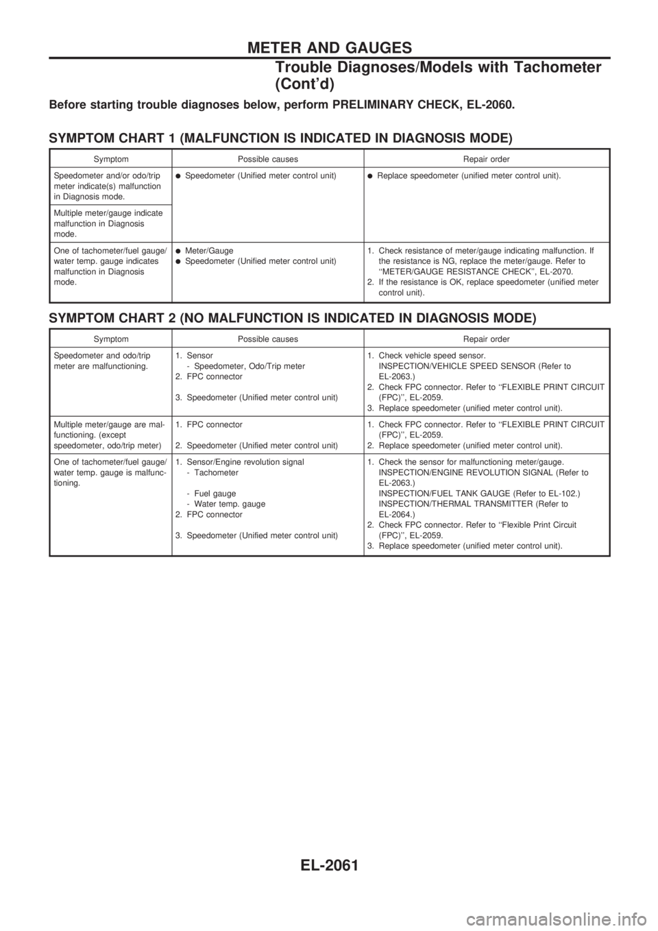
Before starting trouble diagnoses below, perform PRELIMINARY CHECK, EL-2060.
SYMPTOM CHART 1 (MALFUNCTION IS INDICATED IN DIAGNOSIS MODE)
Symptom Possible causes Repair order
Speedometer and/or odo/trip
meter indicate(s) malfunction
in Diagnosis mode.
lSpeedometer (Unified meter control unit)lReplace speedometer (unified meter control unit).
Multiple meter/gauge indicate
malfunction in Diagnosis
mode.
One of tachometer/fuel gauge/
water temp. gauge indicates
malfunction in Diagnosis
mode.
lMeter/GaugelSpeedometer (Unified meter control unit)1. Check resistance of meter/gauge indicating malfunction. If
the resistance is NG, replace the meter/gauge. Refer to
``METER/GAUGE RESISTANCE CHECK'', EL-2070.
2. If the resistance is OK, replace speedometer (unified meter
control unit).
SYMPTOM CHART 2 (NO MALFUNCTION IS INDICATED IN DIAGNOSIS MODE)
Symptom Possible causes Repair order
Speedometer and odo/trip
meter are malfunctioning.1. Sensor
- Speedometer, Odo/Trip meter
2. FPC connector
3. Speedometer (Unified meter control unit)1. Check vehicle speed sensor.
INSPECTION/VEHICLE SPEED SENSOR (Refer to
EL-2063.)
2. Check FPC connector. Refer to ``FLEXIBLE PRINT CIRCUIT
(FPC)'', EL-2059.
3. Replace speedometer (unified meter control unit).
Multiple meter/gauge are mal-
functioning. (except
speedometer, odo/trip meter)1. FPC connector
2. Speedometer (Unified meter control unit)1. Check FPC connector. Refer to ``FLEXIBLE PRINT CIRCUIT
(FPC)'', EL-2059.
2. Replace speedometer (unified meter control unit).
One of tachometer/fuel gauge/
water temp. gauge is malfunc-
tioning.1. Sensor/Engine revolution signal
- Tachometer
- Fuel gauge
- Water temp. gauge
2. FPC connector
3. Speedometer (Unified meter control unit)1. Check the sensor for malfunctioning meter/gauge.
INSPECTION/ENGINE REVOLUTION SIGNAL (Refer to
EL-2063.)
INSPECTION/FUEL TANK GAUGE (Refer to EL-102.)
INSPECTION/THERMAL TRANSMITTER (Refer to
EL-2064.)
2. Check FPC connector. Refer to ``Flexible Print Circuit
(FPC)'', EL-2059.
3. Replace speedometer (unified meter control unit).
METER AND GAUGES
Trouble Diagnoses/Models with Tachometer
(Cont'd)
EL-2061
Page 239 of 666

Engine Control Harness
HEL802A
HARNESS LAYOUT
EL-2160