1999 DODGE NEON steering
[x] Cancel search: steeringPage 1165 of 1200
cranking. Whenever the Powertrain Control Module
(PCM) sets a Diagnostic Trouble Code (DTC) that
affects vehicle emissions, it illuminates the MIL. If a
problem is detected, the PCM sends a message over
the CCD Bus to the instrument cluster to illuminate
the lamp. The PCM illuminates the MIL only for
DTC's that affect vehicle emissions. The MIL stays
on continuously when the PCM has entered a
Limp-In mode or identified a failed emission compo-
nent or system. The MIL remains on until the DTC
is erased. Refer to the Diagnostic Trouble Code
charts in this group for emission related codes.
Also, the MIL either flashes or illuminates contin-
uously when the PCM detects active engine misfire.
Refer to Misfire Monitoring in this section.
Additionally, the PCM may reset (turn off) the MIL
when one of the following occur:
²PCM does not detect the malfunction for 3 con-
secutive trips (except misfire and fuel system moni-
tors).
²PCM does not detect a malfunction while per-
forming three successive engine misfire or fuel sys-
tem tests. The PCM performs these tests while the
engine is operating within6375 RPM of and within
10 % of the load of the operating condition at which
the malfunction was first detected.
STATE DISPLAY TEST MODE
The switch inputs to the Powertrain Control Mod-
ule (PCM) have two recognized states; HIGH and
LOW. For this reason, the PCM cannot recognize the
difference between a selected switch position versus
an open circuit, a short circuit, or a defective switch.
If the State Display screen shows the change from
HIGH to LOW or LOW to HIGH, assume the entire
switch circuit to the PCM functions properly. From
the state display screen, access either State Display
Inputs and Outputs or State Display Sensors.
CIRCUIT ACTUATION TEST MODE
The Circuit Actuation Test Mode checks for proper
operation of output circuits or devices the Powertrain
Control Module (PCM) may not internally recognize.
The PCM attempts to activate these outputs and
allow an observer to verify proper operation. Most of
the tests provide an audible or visual indication of
device operation (click of relay contacts, fuel spray,
etc.). Except for intermittent conditions, if a device
functions properly during testing, assume the device,
its associated wiring, and driver circuit work cor-
rectly.
DIAGNOSTIC TROUBLE CODES
A Diagnostic Trouble Code (DTC) indicates the
PCM has recognized an abnormal condition in the
system.
²The preferred and most accurate method of
retrieving a DTC is by using the DRB scan tool. The
scan tool supplies detailed diagnostic information
which can be used to more accurately diagnose
causes for a DTC.
Remember that DTC's are the results of a sys-
tem or circuit failure, but do not directly iden-
tify the failed component or components.
NOTE: For a list of DTC's, refer to the charts in this
section.
BULB CHECK
Each time the ignition key is turned to the ON
position, the malfunction indicator (check engine)
lamp on the instrument panel should illuminate for
approximately 2 seconds then go out. This is done for
a bulb check.
OBTAINING DTC'S USING DRB SCAN TOOL
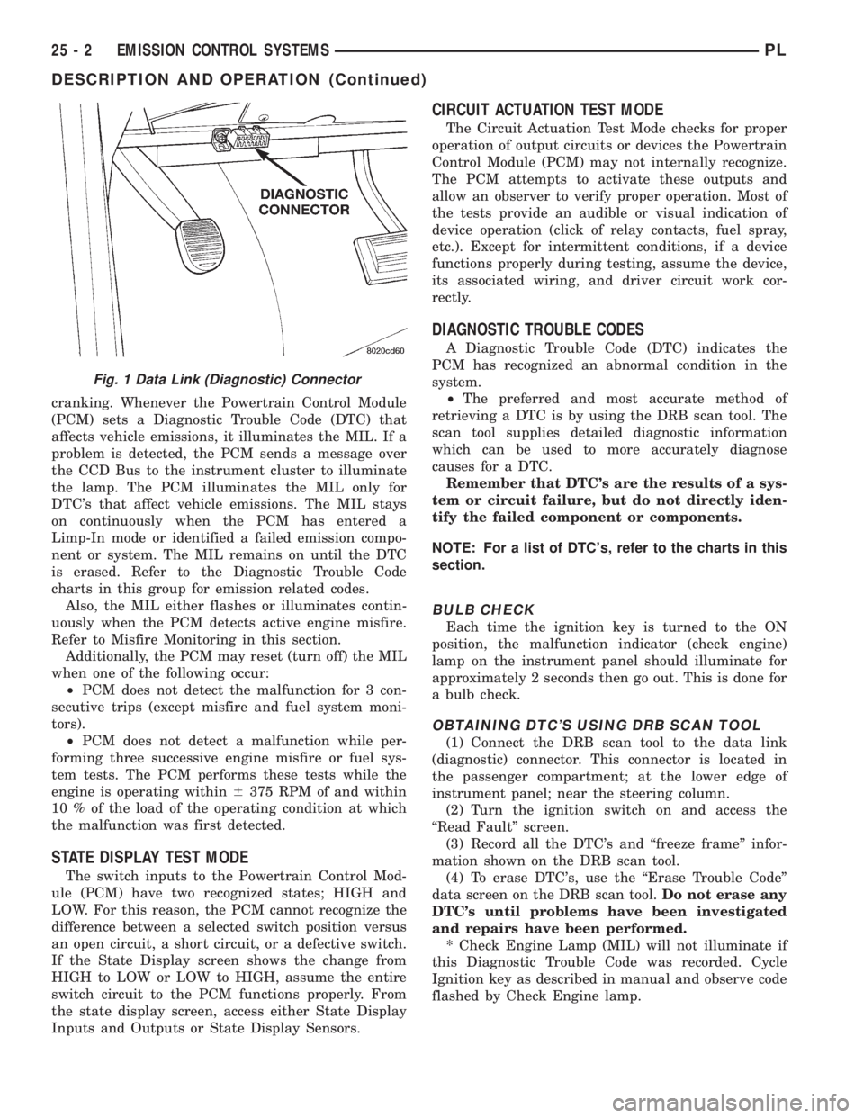
(1) Connect the DRB scan tool to the data link
(diagnostic) connector. This connector is located in
the passenger compartment; at the lower edge of
instrument panel; near the steering column.
(2) Turn the ignition switch on and access the
ªRead Faultº screen.
(3) Record all the DTC's and ªfreeze frameº infor-
mation shown on the DRB scan tool.
(4) To erase DTC's, use the ªErase Trouble Codeº
data screen on the DRB scan tool.Do not erase any
DTC's until problems have been investigated
and repairs have been performed.
* Check Engine Lamp (MIL) will not illuminate if
this Diagnostic Trouble Code was recorded. Cycle
Ignition key as described in manual and observe code
flashed by Check Engine lamp.
Fig. 1 Data Link (Diagnostic) Connector
25 - 2 EMISSION CONTROL SYSTEMSPL
DESCRIPTION AND OPERATION (Continued)
Page 1168 of 1200
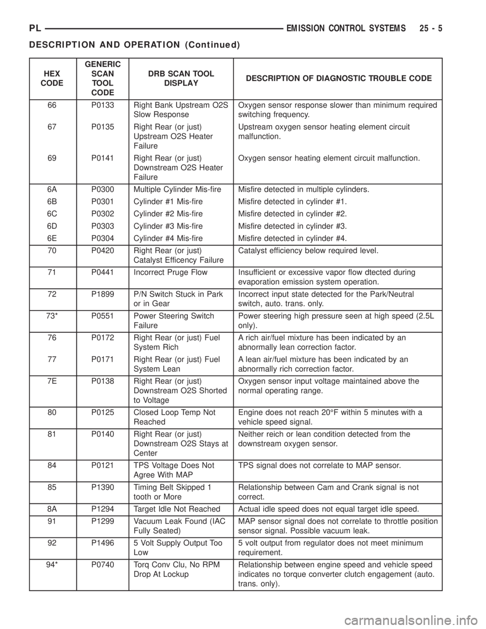
HEX
CODEGENERIC
SCAN
TOOL
CODEDRB SCAN TOOL
DISPLAYDESCRIPTION OF DIAGNOSTIC TROUBLE CODE
66 P0133 Right Bank Upstream O2S
Slow ResponseOxygen sensor response slower than minimum required
switching frequency.
67 P0135 Right Rear (or just)
Upstream O2S Heater
FailureUpstream oxygen sensor heating element circuit
malfunction.
69 P0141 Right Rear (or just)
Downstream O2S Heater
FailureOxygen sensor heating element circuit malfunction.
6A P0300 Multiple Cylinder Mis-fire Misfire detected in multiple cylinders.
6B P0301 Cylinder #1 Mis-fire Misfire detected in cylinder #1.
6C P0302 Cylinder #2 Mis-fire Misfire detected in cylinder #2.
6D P0303 Cylinder #3 Mis-fire Misfire detected in cylinder #3.
6E P0304 Cylinder #4 Mis-fire Misfire detected in cylinder #4.
70 P0420 Right Rear (or just)
Catalyst Efficency FailureCatalyst efficiency below required level.
71 P0441 Incorrect Pruge Flow Insufficient or excessive vapor flow dtected during
evaporation emission system operation.
72 P1899 P/N Switch Stuck in Park
or in GearIncorrect input state detected for the Park/Neutral
switch, auto. trans. only.
73* P0551 Power Steering Switch
FailurePower steering high pressure seen at high speed (2.5L
only).
76 P0172 Right Rear (or just) Fuel
System RichA rich air/fuel mixture has been indicated by an
abnormally lean correction factor.
77 P0171 Right Rear (or just) Fuel
System LeanA lean air/fuel mixture has been indicated by an
abnormally rich correction factor.
7E P0138 Right Rear (or just)
Downstream O2S Shorted
to VoltageOxygen sensor input voltage maintained above the
normal operating range.
80 P0125 Closed Loop Temp Not
ReachedEngine does not reach 20ÉF within 5 minutes with a
vehicle speed signal.
81 P0140 Right Rear (or just)
Downstream O2S Stays at
CenterNeither reich or lean condition detected from the
downstream oxygen sensor.
84 P0121 TPS Voltage Does Not
Agree With MAPTPS signal does not correlate to MAP sensor.
85 P1390 Timing Belt Skipped 1
tooth or MoreRelationship between Cam and Crank signal is not
correct.
8A P1294 Target Idle Not Reached Actual idle speed does not equal target idle speed.
91 P1299 Vacuum Leak Found (IAC
Fully Seated)MAP sensor signal does not correlate to throttle position
sensor signal. Possible vacuum leak.
92 P1496 5 Volt Supply Output Too
Low5 volt output from regulator does not meet minimum
requirement.
94* P0740 Torq Conv Clu, No RPM
Drop At LockupRelationship between engine speed and vehicle speed
indicates no torque converter clutch engagement (auto.
trans. only).
PLEMISSION CONTROL SYSTEMS 25 - 5
DESCRIPTION AND OPERATION (Continued)
Page 1182 of 1200
DIAGNOSIS AND TESTING
EGR SYSTEM ON-BOARD DIAGNOSTICS
The PCM performs an on-board diagnostic check of
the EGR system. The diagnostic system uses the
electronic EGR transducer for the system tests.
The diagnostic check activates only during selected
engine/driving conditions. When the conditions are
met, the PCM energizes the transducer solenoid to
disable the EGR. The PCM checks for a change in
the heated oxygen sensor signal. If the air-fuel mix-
ture goes lean, the PCM will attempt to enrichen the
mixture. The PCM registers a Diagnostic Trouble
Code (DTC) if the EGR system is not operating cor-
rectly. After registering a DTC, the PCM turns on the
malfunction indicator (Check Engine) lamp after 2
consecutive trips. There are 2 types of failures sensed
by the PCM. The first is a short or open in the elec-
trical solenoid circuit. the second is a mechhanical
failure or loss of vacuum. The Malfunction Indicator
Lamp (MIL) indicates the need for service.
If a problem is indicated by the MIL and a DTC for
the EGR system is set, check for proper operation of
the EGR system. Use the System Test, EGR Gas
Flow Test. If the EGR system tests properly, check
the system using the DRB scan tool. Refer to
On-Board Diagnosis sections in this Group. Also,
refer to the DRB scan tool and the appropriate Pow-
ertrain Diagnostics Procedure manual.
EGR SYSTEM TEST
WARNING: APPLY PARKING BRAKE AND/OR
BLOCK WHEELS BEFORE TESTING THE EGR SYS-
TEM.
(1) Check the condition of all EGR system hoses
and tubes for leaks, blockages, cracks, kinks and
hardening of rubber hoses. Repair and correct these
conditions before performing any tests.
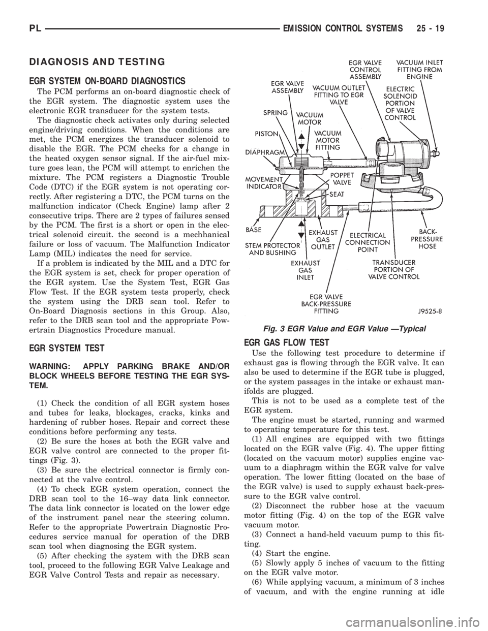
(2) Be sure the hoses at both the EGR valve and
EGR valve control are connected to the proper fit-
tings (Fig. 3).
(3) Be sure the electrical connector is firmly con-
nected at the valve control.
(4) To check EGR system operation, connect the
DRB scan tool to the 16±way data link connector.
The data link connector is located on the lower edge
of the instrument panel near the steering column.
Refer to the appropriate Powertrain Diagnostic Pro-
cedures service manual for operation of the DRB
scan tool when diagnosing the EGR system.
(5) After checking the system with the DRB scan
tool, proceed to the following EGR Valve Leakage and
EGR Valve Control Tests and repair as necessary.
EGR GAS FLOW TEST
Use the following test procedure to determine if
exhaust gas is flowing through the EGR valve. It can
also be used to determine if the EGR tube is plugged,
or the system passages in the intake or exhaust man-
ifolds are plugged.
This is not to be used as a complete test of the
EGR system.
The engine must be started, running and warmed
to operating temperature for this test.
(1) All engines are equipped with two fittings
located on the EGR valve (Fig. 4). The upper fitting
(located on the vacuum motor) supplies engine vac-
uum to a diaphragm within the EGR valve for valve
operation. The lower fitting (located on the base of
the EGR valve) is used to supply exhaust back-pres-
sure to the EGR valve control.
(2) Disconnect the rubber hose at the vacuum
motor fitting (Fig. 4) on the top of the EGR valve
vacuum motor.
(3) Connect a hand-held vacuum pump to this fit-
ting.
(4) Start the engine.
(5) Slowly apply 5 inches of vacuum to the fitting
on the EGR valve motor.
(6) While applying vacuum, a minimum of 3 inches
of vacuum, and with the engine running at idle
Fig. 3 EGR Value and EGR Value ÐTypical
PLEMISSION CONTROL SYSTEMS 25 - 19
Page 1200 of 1200
GROUP TAB LOCATOR
INIntroduction
INaIntroduction
0Lubrication and Maintenance
2Suspension
3Differential and Driveline
5Brakes
6Clutch
6aClutch
7Cooling
8ABattery
8BStarting
8CCharging System
8CaCharging System
8DIgnition System
8EInstrument Panel and Systems
8EaInstrument Panel and Systems
8FAudio System
8GHorns
8HVehicle Speed Control System
8HaVehicle Speed Control System
8JTurn Signal and Flashers
8KWindshield Wipers and Washers
8KaWindshield Wipers and Washers
8LLamps
8LaLamps
8MRestraint System
8NElectrically Heated Systems
8NaElectrically Heated Systems
8PPower Door Locks
8QaImmobilizer System
8SPower Windows
8TPower Mirrors
8TaPower Mirrors
8UChime Warning/Reminder System
8WWiring Diagrams - LHD and RHD
9Engine
9aEngine
11Exhaust System and Intake Manifold
11aExhaust System and Intake Manifold
13Frame and Bumpers
13aFrame and Bumpers
14Fuel System
14aFuel System - 1.8L Engine
19Steering
19aSteering
21Transaxle
21aTransaxle
22Tires and Wheels
23Body
24Heating and Air Conditioning
25Emission Control Systems
25aEmission Control System - 1.8L Engine