1999 DODGE NEON engine oil
[x] Cancel search: engine oilPage 814 of 1200
ENGINE
CONTENTS
page
1.8L SOHC ENGINE...................... 1
1.8L SOHC ENGINE
INDEX
page
GENERAL INFORMATION
1.8L SOHC ENGINE...................... 1
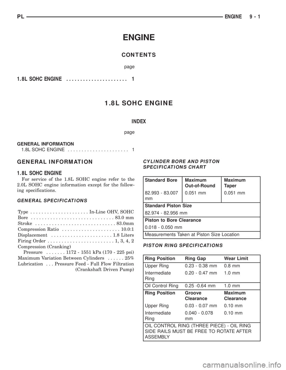
GENERAL INFORMATION
1.8L SOHC ENGINE
For service of the 1.8L SOHC engine refer to the
2.0L SOHC engine information except for the follow-
ing specifications.
GENERAL SPECIFICATIONS
Type .....................In-Line OHV, SOHC
Bore..............................83.0 mm
Stroke.............................83.0mm
Compression Ratio.....................10.0:1
Displacement......................1.8Liters
Firing Order........................1,3,4,2
Compression (Cranking)
Pressure.......1172-1551 kPa (170 - 225 psi)
Maximum Variation Between Cylinders......25%
Lubrication . . . Pressure Feed - Full Flow Filtration
(Crankshaft Driven Pump)
CYLINDER BORE AND PISTON
SPECIFICATIONS CHART
Standard Bore Maximum
Out-of-RoundMaximum
Taper
82.993 - 83.007
mm0.051 mm 0.051 mm
Standard Piston Size
82.974 - 82.956 mm
Piston to Bore Clearance
0.018 - 0.050 mm
Measurements Taken at Piston Size Location
PISTON RING SPECIFICATIONS
Ring Position Ring Gap Wear Limit
Upper Ring 0.23 - 0.38 mm 0.8 mm
Intermediate
Ring0.20 - 0.47 mm 1.0 mm
Oil Control Ring 0.25 -0.64 mm 1.0 mm
Ring Position Groove
ClearanceMaximum
Clearance
Upper Ring 0.03 - 0.07 mm 0.10 mm
Intermediate
Ring0.040 - 0.078
mm0.10 mm
OIL CONTROL RING (THREE PIECE) - OIL RING
SIDE RAILS MUST BE FREE TO ROTATE AFTER
ASSEMBLY
PLENGINE 9 - 1
Page 815 of 1200
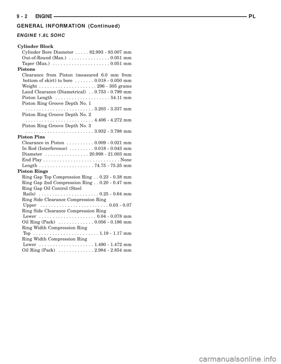
ENGINE 1.8L SOHC
Cylinder Block
Cylinder Bore Diameter.....82.993 - 83.007 mm
Out-of-Round (Max.)...............0.051 mm
Taper (Max.).....................0.051 mm
Pistons
Clearance from Piston (measured 6.0 mm from
bottom of skirt) to bore.......0.018 - 0.050 mm
Weight.....................296-305grams
Land Clearance (Diametrical) . . 0.753 - 0.799 mm
Piston Length....................54.11 mm
Piston Ring Groove Depth No. 1
.........................3.203 - 3.337 mm
Piston Ring Groove Depth No. 2
.........................4.406 - 4.272 mm
Piston Ring Groove Depth No. 3
.........................3.932 - 3.798 mm
Piston Pins
Clearance in Piston..........0.009 - 0.021 mm
In Rod (Interference).........0.018 - 0.043 mm
Diameter................20.998 - 21.003 mm
End Play............................None
Length....................74.75 - 75.25 mm
Piston Rings
Ring Gap Top Compression Ring . . 0.23 - 0.38 mm
Ring Gap 2nd Compression Ring . . 0.20 - 0.47 mm
Ring Gap Oil Control (Steel
Rails)......................0.25 - 0.64 mm
Ring Side Clearance Compression Ring
Upper.........................0.03 - 0.07
Ring Side Clearance Compression Ring
Lower.....................0.04 - 0.078 mm
Oil Ring (Pack).............0.056 - 0.186 mm
Ring Width Compression Ring
Top ........................1.19 - 1.17 mm
Ring Width Compression Ring
Lower....................1.490 - 1.472 mm
Oil Ring (Pack).............2.984 - 2.854 mm
9 - 2 ENGINEPL
GENERAL INFORMATION (Continued)
Page 823 of 1200
INSTALLATION
Before installing manifold. Clean all mating sur-
faces. Replace all seals, with new seals. All intakemanifold fasteners and washers are to be discarded
andNEWfasteners and washers are to be used.
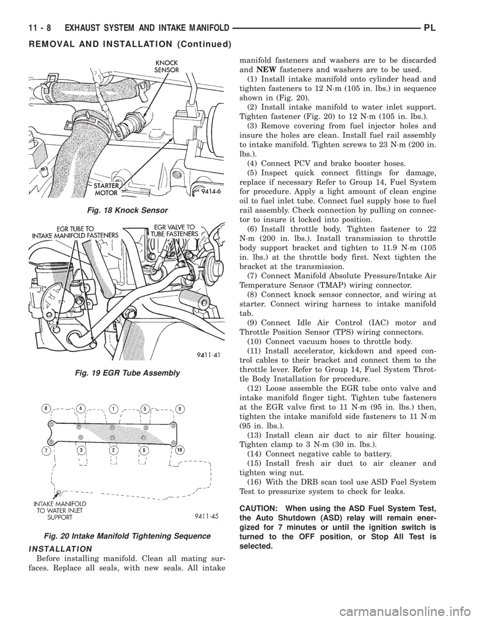
(1) Install intake manifold onto cylinder head and
tighten fasteners to 12 N´m (105 in. lbs.) in sequence
shown in (Fig. 20).
(2) Install intake manifold to water inlet support.
Tighten fastener (Fig. 20) to 12 N´m (105 in. lbs.).
(3) Remove covering from fuel injector holes and
insure the holes are clean. Install fuel rail assembly
to intake manifold. Tighten screws to 23 N´m (200 in.
lbs.).
(4) Connect PCV and brake booster hoses.
(5) Inspect quick connect fittings for damage,
replace if necessary Refer to Group 14, Fuel System
for procedure. Apply a light amount of clean engine
oil to fuel inlet tube. Connect fuel supply hose to fuel
rail assembly. Check connection by pulling on connec-
tor to insure it locked into position.
(6) Install throttle body. Tighten fastener to 22
N´m (200 in. lbs.). Install transmission to throttle
body support bracket and tighten to 11.9 N´m (105
in. lbs.) at the throttle body first. Next tighten the
bracket at the transmission.
(7) Connect Manifold Absolute Pressure/Intake Air
Temperature Sensor (TMAP) wiring connector.
(8) Connect knock sensor connector, and wiring at
starter. Connect wiring harness to intake manifold
tab.
(9) Connect Idle Air Control (IAC) motor and
Throttle Position Sensor (TPS) wiring connectors.
(10) Connect vacuum hoses to throttle body.
(11) Install accelerator, kickdown and speed con-
trol cables to their bracket and connect them to the
throttle lever. Refer to Group 14, Fuel System Throt-
tle Body Installation for procedure.
(12) Loose assemble the EGR tube onto valve and
intake manifold finger tight. Tighten tube fasteners
at the EGR valve first to 11 N´m (95 in. lbs.) then,
tighten the intake manifold side fasteners to 11 N´m
(95 in. lbs.).
(13) Install clean air duct to air filter housing.
Tighten clamp to 3 N´m (30 in. lbs.).
(14) Connect negative cable to battery.
(15) Install fresh air duct to air cleaner and
tighten wing nut.
(16) With the DRB scan tool use ASD Fuel System
Test to pressurize system to check for leaks.
CAUTION: When using the ASD Fuel System Test,
the Auto Shutdown (ASD) relay will remain ener-
gized for 7 minutes or until the ignition switch is
turned to the OFF position, or Stop All Test is
selected.
Fig. 18 Knock Sensor
Fig. 19 EGR Tube Assembly
Fig. 20 Intake Manifold Tightening Sequence
11 - 8 EXHAUST SYSTEM AND INTAKE MANIFOLDPL
REMOVAL AND INSTALLATION (Continued)
Page 826 of 1200

INSTALLATION
Before installing manifolds. Clean all mating sur-
faces. Replace all gaskets, with new.
(1) Assemble lower manifold to upper (if sepa-
rated) and tighten bolts in sequence shown in (Fig.
29) to 28 N´m (250 in. lbs.).
(2) Install intake manifold onto cylinder head and
tighten fasteners to 28 N´m (250 in. lbs.) in sequence
shown in (Fig. 30).
(3) Remove covering from fuel injector holes and
insure the holes are clean. Install fuel rail assembly
to intake manifold. Tighten screws to 23 N´m (200 in.
lbs.).
(4) Connect PCV and brake booster hoses.
(5) Inspect quick connect fittings for damage,
replace if necessary Refer to Group 14, Fuel System
for procedure. Apply a light amount of clean engine
oil to fuel inlet tube. Connect fuel supply hose to fuel
rail assembly. Check connection by pulling on connec-
tor to insure it locked into position.
(6) Connect heater tube and hose to intake mani-
fold.
(7) Connect upper radiator hose and coolant recov-
ery hose.
(8) Connect coolant temperature sensor wiring con-
nector.
(9) Install throttle body. Tighten fastener to 22
N´m (200 in. lbs.).
(10) Connect Manifold Absolute Pressure/Intake
Air Temperature Sensor (TMAP) wiring connector.(11) Connect knock sensor connector and starter
wires. Connect wiring harness to heater tube tab.
(12) Connect Idle Air Control (IAC) motor and
Throttle Position Sensor (TPS) wiring connectors.
(13) Connect vacuum hoses to throttle body.
(14) Install accelerator, kickdown and speed con-
trol cables to their bracket and connect them to the
throttle lever. Refer to Group 14, Fuel System Throt-
tle Body Installation for procedure.
(15) Loose assemble the EGR tube onto valve and
intake manifold finger tight. Tighten tube fasteners
at the EGR valve first to 11 N´m (95 in. lbs.) then,
tighten the intake manifold side fasteners to 11 N´m
(95 in. lbs.).
(16) Install fresh air duct to air filter housing.
Tighten clamp to 3 N´m (25 in. lbs.).
(17) Connect negative cable to battery.
(18) With the DRB scan tool use ASD Fuel System
Test to pressurize system to check for leaks.
CAUTION: When using the ASD Fuel System Test,
the Auto Shutdown (ASD) relay will remain ener-
gized for 7 minutes or until the ignition switch is
turned to the OFF position, or Stop All Test is
selected.
EXHAUST MANIFOLD
REMOVAL
(1) Remove air cleaner assembly and bracket.
(2) Remove exhaust manifold heat shield (Fig. 31).
(3) Disconnect upstream heated oxygen sensor con-
nector.
Fig. 29 Lower Intake Manifold to Upper Tightening
Sequence
Fig. 30 Intake Manifold To Cylinder Head Tightening
Sequence
Fig. 31 Exhaust Manifold Heat Shield
PLEXHAUST SYSTEM AND INTAKE MANIFOLD 11 - 11
REMOVAL AND INSTALLATION (Continued)
Page 852 of 1200
The hose clamps have rolled edges to prevent the
clamp from cutting into the hose. Only use clamps
that are original equipment or equivalent. Other
types of clamps may cut into the hoses and cause
high pressure fuel leaks. Tighten hose clamps to 1
N´m (10 in. lbs.) torque.
QUICK-CONNECT FITTINGS
REMOVAL
When disconnecting a quick-connect fitting, the
retainer will remain on the fuel tube nipple.
WARNING: RELEASE FUEL SYSTEM PRESSURE
BEFORE DISCONNECTING A QUICK-CONNECT FIT-
TINGS. REFER TO THE FUEL PRESSURE RELEASE
PROCEDURE.
(1) Disconnect negative cable from battery.
(2) Perform Fuel Pressure Release Procedure.
Refer to the Fuel Pressure Release Procedure in this
section.
(3) Squeeze retainer tabs together and pull fuel
tube/quick-connect fitting assembly off of fuel tube
nipple. The retainer will remain on fuel tube.
INSTALLATION
CAUTION: Never install a quick-connect fitting
without the retainer being either on the fuel tube or
already in the quick-connect fitting. In either case,
ensure the retainer locks securely into the quick-
connect fitting by firmly pulling on fuel tube and fit-
ting to ensure it is secured.
(1) Using a clean lint free cloth, clean the fuel tube
nipple and retainer.
(2) Prior to connecting the fitting to the fuel tube,
coat the fuel tube nipple with clean 30 weight engine
oil.
(3) Push the quick-connect fitting over the fuel
tube until theretainer seats and a click is heard.
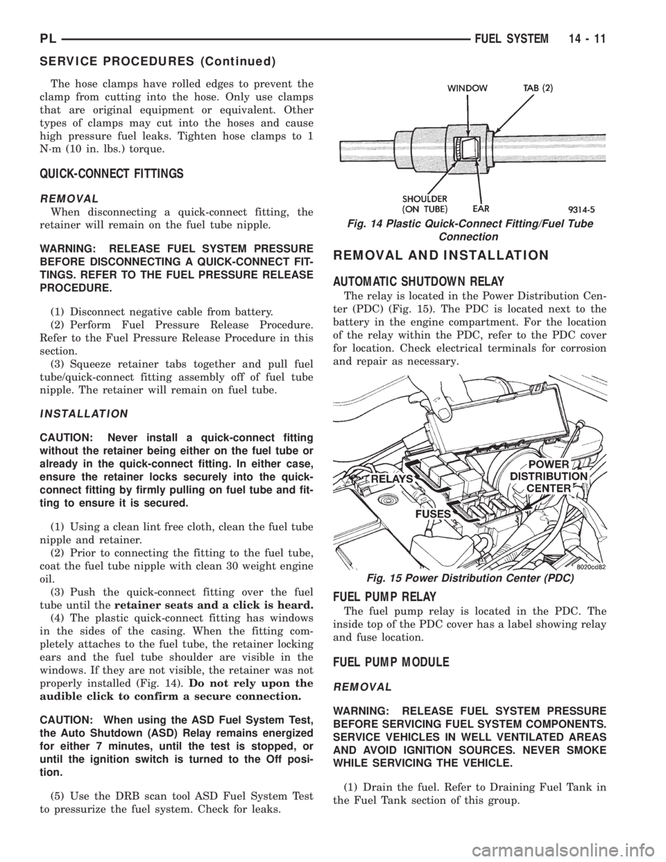
(4) The plastic quick-connect fitting has windows
in the sides of the casing. When the fitting com-
pletely attaches to the fuel tube, the retainer locking
ears and the fuel tube shoulder are visible in the
windows. If they are not visible, the retainer was not
properly installed (Fig. 14).Do not rely upon the
audible click to confirm a secure connection.
CAUTION: When using the ASD Fuel System Test,
the Auto Shutdown (ASD) Relay remains energized
for either 7 minutes, until the test is stopped, or
until the ignition switch is turned to the Off posi-
tion.
(5) Use the DRB scan tool ASD Fuel System Test
to pressurize the fuel system. Check for leaks.
REMOVAL AND INSTALLATION
AUTOMATIC SHUTDOWN RELAY
The relay is located in the Power Distribution Cen-
ter (PDC) (Fig. 15). The PDC is located next to the
battery in the engine compartment. For the location
of the relay within the PDC, refer to the PDC cover
for location. Check electrical terminals for corrosion
and repair as necessary.
FUEL PUMP RELAY
The fuel pump relay is located in the PDC. The
inside top of the PDC cover has a label showing relay
and fuse location.
FUEL PUMP MODULE
REMOVAL
WARNING: RELEASE FUEL SYSTEM PRESSURE
BEFORE SERVICING FUEL SYSTEM COMPONENTS.
SERVICE VEHICLES IN WELL VENTILATED AREAS
AND AVOID IGNITION SOURCES. NEVER SMOKE
WHILE SERVICING THE VEHICLE.
(1) Drain the fuel. Refer to Draining Fuel Tank in
the Fuel Tank section of this group.
Fig. 14 Plastic Quick-Connect Fitting/Fuel Tube
Connection
Fig. 15 Power Distribution Center (PDC)
PLFUEL SYSTEM 14 - 11
SERVICE PROCEDURES (Continued)
Page 853 of 1200
WARNING: THE FUEL RESERVOIR OF THE FUEL
PUMP MODULE DOES NOT EMPTY OUT WHEN THE
TANK IS DRAINED. THE FUEL IN THE RESERVOIR
WILL SPILL OUT WHEN THE MODULE IS
REMOVED.
(2) Disconnect fuel line from fuel pump module by
depressing quick connect retainers with thumb and
fore finger.
(3) Slide fuel pump module electrical connecter
lock to unlock.
(4) Disconnect the electrical connection from the
fuel pump module, by pushing down on connector
retainer and pulling connector off of module.
(5) Use a transmission jack to support the fuel
tank. remove bolts from fuel tank straps.
(6) Lower tank slightly.
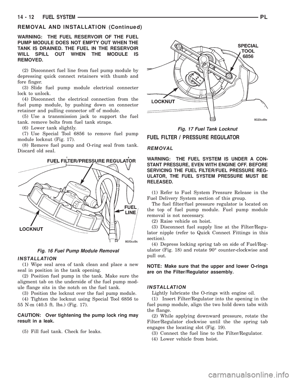
(7) Use Special Tool 6856 to remove fuel pump
module locknut (Fig. 17).
(8) Remove fuel pump and O-ring seal from tank.
Discard old seal.
INSTALLATION
(1) Wipe seal area of tank clean and place a new
seal in position in the tank opening.
(2) Position fuel pump in the tank. Make sure the
aligment tab on the underside of the fuel pump mod-
ule flange sits in the notch on the fuel tank.
(3)
Position the locknut over the fuel pump module.
(4) Tighten the locknut using Special Tool 6856 to
55 N´m (40.5 ft. lbs.) (Fig. 17).
CAUTION: Over tightening the pump lock ring may
result in a leak.
(5) Fill fuel tank. Check for leaks.
FUEL FILTER / PRESSURE REGULATOR
REMOVAL
WARNING: THE FUEL SYSTEM IS UNDER A CON-
STANT PRESSURE, EVEN WITH ENGINE OFF. BEFORE
SERVICING THE FUEL FILTER/FUEL PRESSURE REG-
ULATOR, THE FUEL SYSTEM PRESSURE MUST BE
RELEASED.
(1) Refer to Fuel System Pressure Release in the
Fuel Delivery System section of this group.
The fuel filter/fuel pressure regulator is located on
the top of fuel pump module. Fuel pump module
removal is not necessary.
(2) Raise vehicle on hoist.
(3) Disconnect fuel supply line at the Filter/Regu-
lator nipple (refer to Quick Connect Fittings in this
section).
(4) Depress locking spring tab on side of Fuel/Reg-
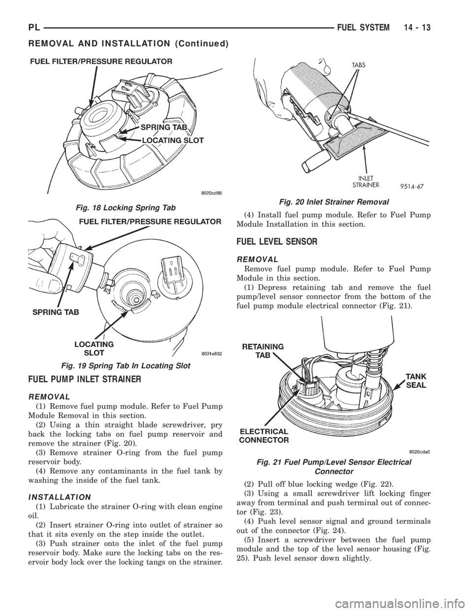
ulator (Fig. 18) and rotate 90É counter-clockwise and
pull out.
NOTE: Make sure that the upper and lower O-rings
are on the Filter/Regulator assembly.
INSTALLATION
Lightly lubricate the O-rings with engine oil.
(1) Insert Filter/Regulator into the opening in the
fuel pump module, align the two hold down tabs with
the flange.
(2) While applying downward pressure, rotate the
Filter/Regulator clockwise until the the spring tab
engages the locating slot (Fig. 19).
(3) Connect the fuel line to the Filter/Regulator.
(4) Lower vehicle from hoist.
Fig. 16 Fuel Pump Module Removal
Fig. 17 Fuel Tank Locknut
14 - 12 FUEL SYSTEMPL
REMOVAL AND INSTALLATION (Continued)
Page 854 of 1200
FUEL PUMP INLET STRAINER
REMOVAL
(1) Remove fuel pump module. Refer to Fuel Pump
Module Removal in this section.
(2) Using a thin straight blade screwdriver, pry
back the locking tabs on fuel pump reservoir and
remove the strainer (Fig. 20).
(3) Remove strainer O-ring from the fuel pump
reservoir body.
(4) Remove any contaminants in the fuel tank by
washing the inside of the fuel tank.
INSTALLATION
(1) Lubricate the strainer O-ring with clean engine
oil.
(2) Insert strainer O-ring into outlet of strainer so
that it sits evenly on the step inside the outlet.
(3) P
ush strainer onto the inlet of the fuel pump
reservoir body. Make sure the locking tabs on the res-
ervoir body lock over the locking tangs on the strainer.
(4) Install fuel pump module. Refer to Fuel Pump
Module Installation in this section.
FUEL LEVEL SENSOR
REMOVAL
Remove fuel pump module. Refer to Fuel Pump
Module in this section.
(1) Depress retaining tab and remove the fuel
pump/level sensor connector from the bottom of the
fuel pump module electrical connector (Fig. 21).
(2) Pull off blue locking wedge (Fig. 22).
(3) Using a small screwdriver lift locking finger
away from terminal and push terminal out of connec-
tor (Fig. 23).
(4) Push level sensor signal and ground terminals
out of the connector (Fig. 24).
(5) Insert a screwdriver between the fuel pump
module and the top of the level sensor housing (Fig.
25). Push level sensor down slightly.
Fig. 18 Locking Spring Tab
Fig. 19 Spring Tab In Locating Slot
Fig. 20 Inlet Strainer Removal
Fig. 21 Fuel Pump/Level Sensor Electrical
Connector
PLFUEL SYSTEM 14 - 13
REMOVAL AND INSTALLATION (Continued)
Page 856 of 1200
(5) Remove fuel rail mounting screws.
(6) Lift rail off of intake manifold. Cover the fuel
injector openings in the intake manifold.
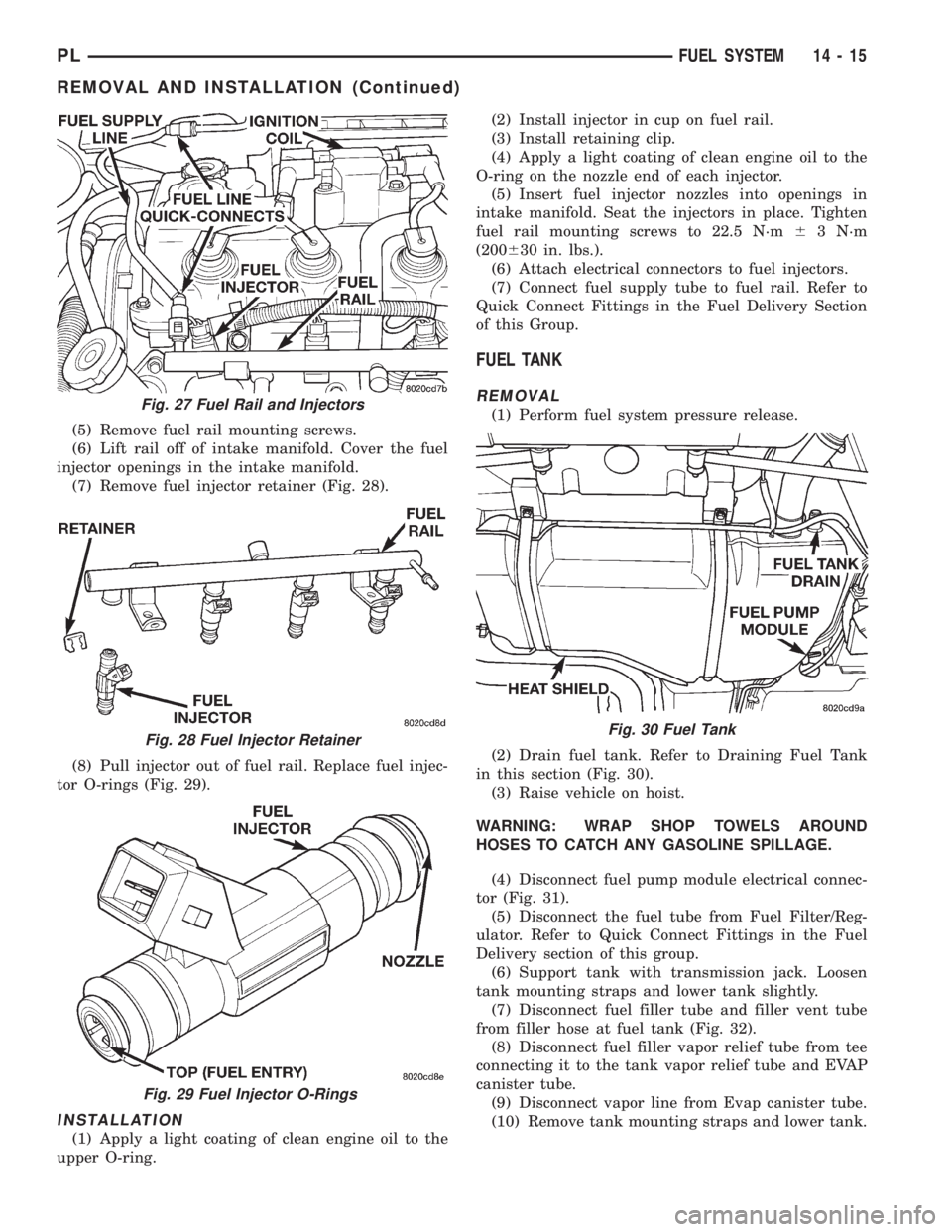
(7) Remove fuel injector retainer (Fig. 28).
(8) Pull injector out of fuel rail. Replace fuel injec-
tor O-rings (Fig. 29).
INSTALLATION
(1) Apply a light coating of clean engine oil to the
upper O-ring.(2) Install injector in cup on fuel rail.
(3) Install retaining clip.
(4) Apply a light coating of clean engine oil to the
O-ring on the nozzle end of each injector.
(5) Insert fuel injector nozzles into openings in
intake manifold. Seat the injectors in place. Tighten
fuel rail mounting screws to 22.5 N´m63 N´m
(200630 in. lbs.).
(6) Attach electrical connectors to fuel injectors.
(7) Connect fuel supply tube to fuel rail. Refer to
Quick Connect Fittings in the Fuel Delivery Section
of this Group.
FUEL TANK
REMOVAL
(1) Perform fuel system pressure release.
(2) Drain fuel tank. Refer to Draining Fuel Tank
in this section (Fig. 30).
(3) Raise vehicle on hoist.
WARNING: WRAP SHOP TOWELS AROUND
HOSES TO CATCH ANY GASOLINE SPILLAGE.
(4) Disconnect fuel pump module electrical connec-
tor (Fig. 31).
(5) Disconnect the fuel tube from Fuel Filter/Reg-
ulator. Refer to Quick Connect Fittings in the Fuel
Delivery section of this group.
(6) Support tank with transmission jack. Loosen
tank mounting straps and lower tank slightly.
(7) Disconnect fuel filler tube and filler vent tube
from filler hose at fuel tank (Fig. 32).
(8) Disconnect fuel filler vapor relief tube from tee
connecting it to the tank vapor relief tube and EVAP
canister tube.
(9) Disconnect vapor line from Evap canister tube.
(10) Remove tank mounting straps and lower tank.Fig. 27 Fuel Rail and Injectors
Fig. 28 Fuel Injector Retainer
Fig. 29 Fuel Injector O-Rings
Fig. 30 Fuel Tank
PLFUEL SYSTEM 14 - 15
REMOVAL AND INSTALLATION (Continued)