1999 DODGE NEON engine oil
[x] Cancel search: engine oilPage 779 of 1200
(18) Lower vehicle. Remove air cleaner assembly.
(19) Remove power steering pump and reservoir,
Set them aside.
(20) Remove A/C compressor.
(21) Remove ground straps to body.
(22) Raise vehicle enough to allow engine dolly
and cradle Special Tools 6135 and 6710 to be
installed under vehicle.
(23) Loosen engine support posts to allow move-
ment for positioning onto engine locating holes and
flange on the engine bedplate. Lower vehicle and
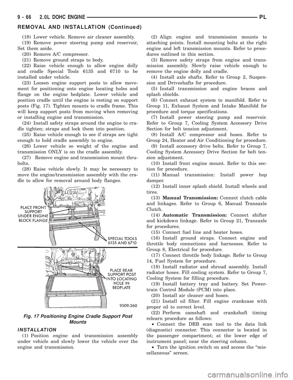
position cradle until the engine is resting on support
posts (Fig. 17). Tighten mounts to cradle frame. This
will keep support posts from moving when removing
or installing engine and transmission.
(24) Install safety straps around the engine to cra-
dle tighten; straps and lock them into position.
(25) Raise vehicle enough to see if straps are tight
enough to hold cradle assembly to engine.
(26) Lower vehicle so weight of the engine and
transmission ONLY is on the cradle assembly.
(27) Remove engine and transmission mount thru-
bolts.
(28) Raise vehicle slowly. It may be necessary to
move the engine/transmission assembly with the cra-
dle to allow for removal around body flanges.
INSTALLATION
(1) Position engine and transmission assembly
under vehicle and slowly lower the vehicle over the
engine and transmission.(2) Align engine and transmission mounts to
attaching points. Install mounting bolts at the right
engine and left transmission mounts. Refer to proce-
dures outlined in this section.
(3) Remove safety straps from engine and trans-
mission assembly. Slowly raise vehicle enough to
remove the engine dolly and cradle.
(4) Install axle shafts. Refer to Group 2, Suspen-
sion and Driveshafts for procedure.
(5) Install transmission and engine braces and
splash shields.
(6) Connect exhaust system to manifold. Refer to
Group 11, Exhaust System and Intake Manifold for
procedure and torque specifications.
(7) Install power steering pump and reservoir.
Refer to Group 7, Cooling System Accessory Drive
Section for belt tension adjustment.
(8) Install A/C compressor and hoses. Refer to
Group 24, Heater and Air Conditioning for procedure.
(9) Install accessory drive belts. Refer to Group 7,
Cooling System Accessory Drive Section for belt ten-
sion adjustment.
(10) Install front engine mount. Refer to this sec-
tion for procedure.
(11) Manual transmission: Install power hop
damper.
(12) Install inner splash shield. Install wheels and
tires.
(13)Manual Transmission:Connect clutch cable
and linkages. Refer to Group 6, Manual Transaxle
Clutch.
(14)Automatic Transmission:Connect shifter
and kickdown linkage. Refer to Group 21, Transaxle
for procedures.
(15) Connect fuel line and heater hoses.
(16) Install ground straps. Connect engine and
throttle body connections and harnesses. Refer to
Group 8, Electrical for procedure.
(17) Connect throttle body linkage. Refer to Group
14, Fuel System for procedure.
(18) Install radiator and shroud assembly. Install
radiator hoses. Fill cooling system. Refer to Group 7,
Cooling System for filling procedure.
(19) Install battery tray and battery. Set Power-
train Control Module (PCM) into place.
(20) Install air cleaner and hoses.
(21) Install oil filter. Fill engine crankcase with
proper oil to correct level.
(22) Perform camshaft and crankshaft timing
relearn procedure as follows:
²Connect the DRB scan tool to the data link
(diagnostic) connector. This connector is located in
the passenger compartment; at the lower edge of
instrument panel; near the steering column.
²Turn the ignition switch on and access the ªmis-
cellaneousº screen.
Fig. 17 Positioning Engine Cradle Support Post
Mounts
9 - 66 2.0L DOHC ENGINEPL
REMOVAL AND INSTALLATION (Continued)
Page 780 of 1200
²Select ªre-learn cam/crankº option and follow
directions on DRB screen.
(23) Start engine and run until operating temper-
ature is reached.
(24) Adjust transmission linkage, if necessary.
CYLINDER HEAD COVER
REMOVAL
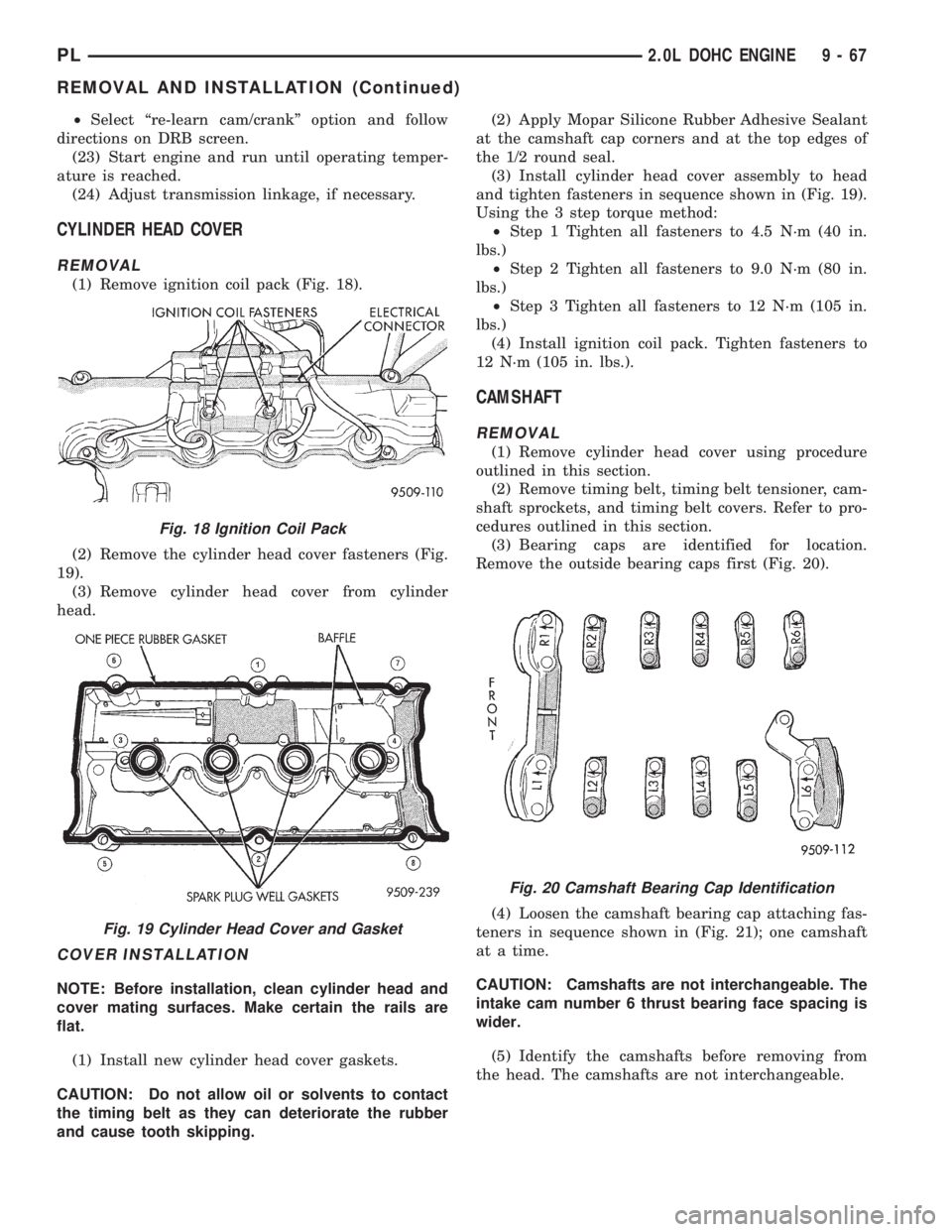
(1) Remove ignition coil pack (Fig. 18).
(2) Remove the cylinder head cover fasteners (Fig.
19).
(3) Remove cylinder head cover from cylinder
head.
COVER INSTALLATION
NOTE: Before installation, clean cylinder head and
cover mating surfaces. Make certain the rails are
flat.
(1) Install new cylinder head cover gaskets.
CAUTION: Do not allow oil or solvents to contact
the timing belt as they can deteriorate the rubber
and cause tooth skipping.(2) Apply Mopar Silicone Rubber Adhesive Sealant
at the camshaft cap corners and at the top edges of
the 1/2 round seal.
(3) Install cylinder head cover assembly to head
and tighten fasteners in sequence shown in (Fig. 19).
Using the 3 step torque method:
²Step 1 Tighten all fasteners to 4.5 N´m (40 in.
lbs.)
²Step 2 Tighten all fasteners to 9.0 N´m (80 in.
lbs.)
²Step 3 Tighten all fasteners to 12 N´m (105 in.
lbs.)
(4) Install ignition coil pack. Tighten fasteners to
12 N´m (105 in. lbs.).
CAMSHAFT
REMOVAL
(1) Remove cylinder head cover using procedure
outlined in this section.
(2) Remove timing belt, timing belt tensioner, cam-
shaft sprockets, and timing belt covers. Refer to pro-
cedures outlined in this section.
(3) Bearing caps are identified for location.
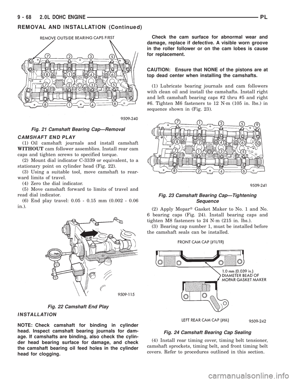
Remove the outside bearing caps first (Fig. 20).
(4) Loosen the camshaft bearing cap attaching fas-
teners in sequence shown in (Fig. 21); one camshaft
at a time.
CAUTION: Camshafts are not interchangeable. The
intake cam number 6 thrust bearing face spacing is
wider.
(5) Identify the camshafts before removing from
the head. The camshafts are not interchangeable.
Fig. 18 Ignition Coil Pack
Fig. 19 Cylinder Head Cover and Gasket
Fig. 20 Camshaft Bearing Cap Identification
PL2.0L DOHC ENGINE 9 - 67
REMOVAL AND INSTALLATION (Continued)
Page 781 of 1200
CAMSHAFT END PLAY
(1) Oil camshaft journals and install camshaft
WITHOUTcam follower assemblies. Install rear cam
caps and tighten screws to specified torque.
(2) Mount dial indicator C-3339 or equivalent, to a
stationary point on cylinder head (Fig. 22).
(3) Using a suitable tool, move camshaft to rear-
ward limits of travel.
(4) Zero the dial indicator.
(5) Move camshaft forward to limits of travel and
read dial indicator.
(6) End play travel: 0.05 - 0.15 mm (0.002 - 0.06
in.).
INSTALLATION
NOTE: Check camshaft for binding in cylinder
head. Inspect camshaft bearing journals for dam-
age. If camshafts are binding, also check the cylin-
der head bearing surface for damage, and check
the camshaft bearing oil feed holes in the cylinder
head for clogging.Check the cam surface for abnormal wear and
damage, replace if defective. A visible worn groove
in the roller follower or on the cam lobes is cause
for replacement.
CAUTION: Ensure that NONE of the pistons are at
top dead center when installing the camshafts.
(1) Lubricate bearing journals and cam followers
with clean oil and install the camshafts. Install right
and left camshaft bearing caps #2 thru #5 and right
#6. Tighten M6 fasteners to 12 N´m (105 in. lbs.) in
sequence shown in (Fig. 23).
(2) Apply MopartGasket Maker to No. 1 and No.
6 bearing caps (Fig. 24). Install bearing caps and
tighten M8 fasteners to 24 N´m (215 in. lbs.).
(3) Bearing cap number 1, must be installed before
the camshaft seals can be installed.
(4) Install rear timing cover, timing belt tensioner,
camshaft sprockets, timing belt, and front timing belt
covers. Refer to procedures outlined in this section.
Fig. 21 Camshaft Bearing CapÐRemoval
Fig. 22 Camshaft End Play
Fig. 23 Camshaft Bearing CapÐTightening
Sequence
Fig. 24 Camshaft Bearing Cap Sealing
9 - 68 2.0L DOHC ENGINEPL
REMOVAL AND INSTALLATION (Continued)
Page 782 of 1200
(5) Install cylinder head cover using procedure out-
lined in this section.
(6) Perform camshaft and crankshaft timing
relearn procedure as follows:
²Step 1: Connect the DRB scan tool to the data
link (diagnostic) connector. This connector is located
in the passenger compartment; at the lower edge of
instrument panel; near the steering column.
²Step 2: Turn the ignition switch on and access
the ªmiscellaneousº screen.
²Step 3: Select re-learn cam/crank option and fol-
low directions on DRB screen.
CAM FOLLOWER AND HYDRAULIC LASH
ADJUSTER ASSEMBLY
REMOVAL
(1) Remove cylinder head cover using procedure
outlined in this section.
(2) Remove timing belt, sprockets and covers using
procedure outlined in this section.
(3) Remove camshaft. Refer to procedure previ-
ously outline this section.
(4) Remove cam follower assemblies from cylinder
head. Keep the cam followers in the order they have
been removed from the head for reassembly. Mark
hydraulic lash adjusters for reassembly in their orig-
inal position. Lash adjusters are serviced as an
assembly.
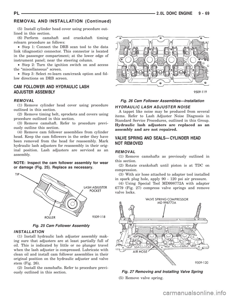
NOTE: Inspect the cam follower assembly for wear
or damage (Fig. 25). Replace as necessary.
INSTALLATION
(1) Install hydraulic lash adjuster assembly mak-
ing sure that adjusters are at least partially full of
oil. This is indicated by little or no plunger travel
when the lash adjuster is compressed. Lubricate with
clean oil and install cam follower assemblies in their
original position on the hydraulic adjuster and valve
stem (Fig. 26).
(2) Install the camshafts. Refer to procedure previ-
ously outlined in this section.
HYDRAULIC LASH ADJUSTER NOISE
A tappet like noise may be produced from several
items. Refer to Lash Adjuster Noise Diagnosis in
Standard Service Procedures, outlined in this Group.
Hydraulic lash adjusters are replaced as an
assembly and are not repaired.
VALVE SPRING AND SEALSÐCYLINDER HEAD
NOT REMOVED
REMOVAL
(1) Remove camshafts as previously outlined in
this section.
(2) Rotate crankshaft until piston is at TDC on
compression.
(3) With air hose attached to adapter tool installed
in spark plug hole, apply 90 - 120 psi air pressure.
(4) Using Special Tool MD998772A with adapter
6779 (Fig. 27) compress valve springs and remove
valve locks.
(5) Remove valve spring.
Fig. 25 Cam Follower Assembly
Fig. 26 Cam Follower AssembliesÐInstallation
Fig. 27 Removing and Installing Valve Spring
PL2.0L DOHC ENGINE 9 - 69
REMOVAL AND INSTALLATION (Continued)
Page 783 of 1200
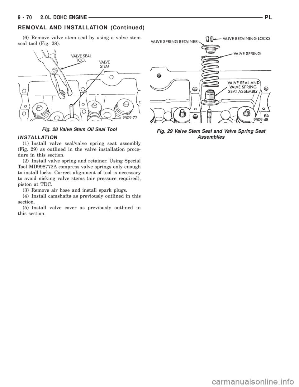
(6) Remove valve stem seal by using a valve stem
seal tool (Fig. 28).
INSTALLATION
(1) Install valve seal/valve spring seat assembly
(Fig. 29) as outlined in the valve installation proce-
dure in this section.
(2) Install valve spring and retainer. Using Special
Tool MD998772A compress valve springs only enough
to install locks. Correct alignment of tool is necessary
to avoid nicking valve stems (air pressure required),
piston at TDC.
(3) Remove air hose and install spark plugs.
(4) Install camshafts as previously outlined in this
section.
(5) Install valve cover as previously outlined in
this section.
Fig. 28 Valve Stem Oil Seal ToolFig. 29 Valve Stem Seal and Valve Spring Seat
Assemblies
9 - 70 2.0L DOHC ENGINEPL
REMOVAL AND INSTALLATION (Continued)
Page 785 of 1200
REMOVAL
(1) Perform fuel system pressure release procedure
before attempting any repairs.Refer to Group 14,
Fuel System.
(2) Disconnect negative battery cable. Drain cool-
ing system. Refer to Group 7, Cooling System.
(3) Remove air cleaner duct and air cleaner, dis-
connect all vacuum lines, electrical wiring and fuel
line from fuel rail and throttle body.
(4) Remove throttle linkage.
(5) Remove accessory drive belts. Refer to Group 7,
Cooling System for procedure.
(6) Remove power brake vacuum hose from intake
manifold.
(7) Raise vehicle and remove exhaust pipe from
manifold.
(8) Remove power steering pump assembly and set
aside.
(9) Disconnect coil pack wiring connector and
remove coil pack from engine.
(10) Remove cam sensor and fuel injectors wiring
connectors.
(11) Remove timing belt, timing belt tensioner, and
camshaft sprocket. Refer to procedure outlined in
this section.
(12) Remove inner timing belt cover.
(13) Remove cylinder head cover.
(14) Remove camshaft and cam follower assem-
blies. Refer to Camshaft Service for removal proce-
dure outlined in this section.
(15) Remove cylinder head bolts.
CAUTION: Use only a plastic scraper to remove
gasket material on the aluminum head sealing sur-
faces to prevent damage to cylinder head.
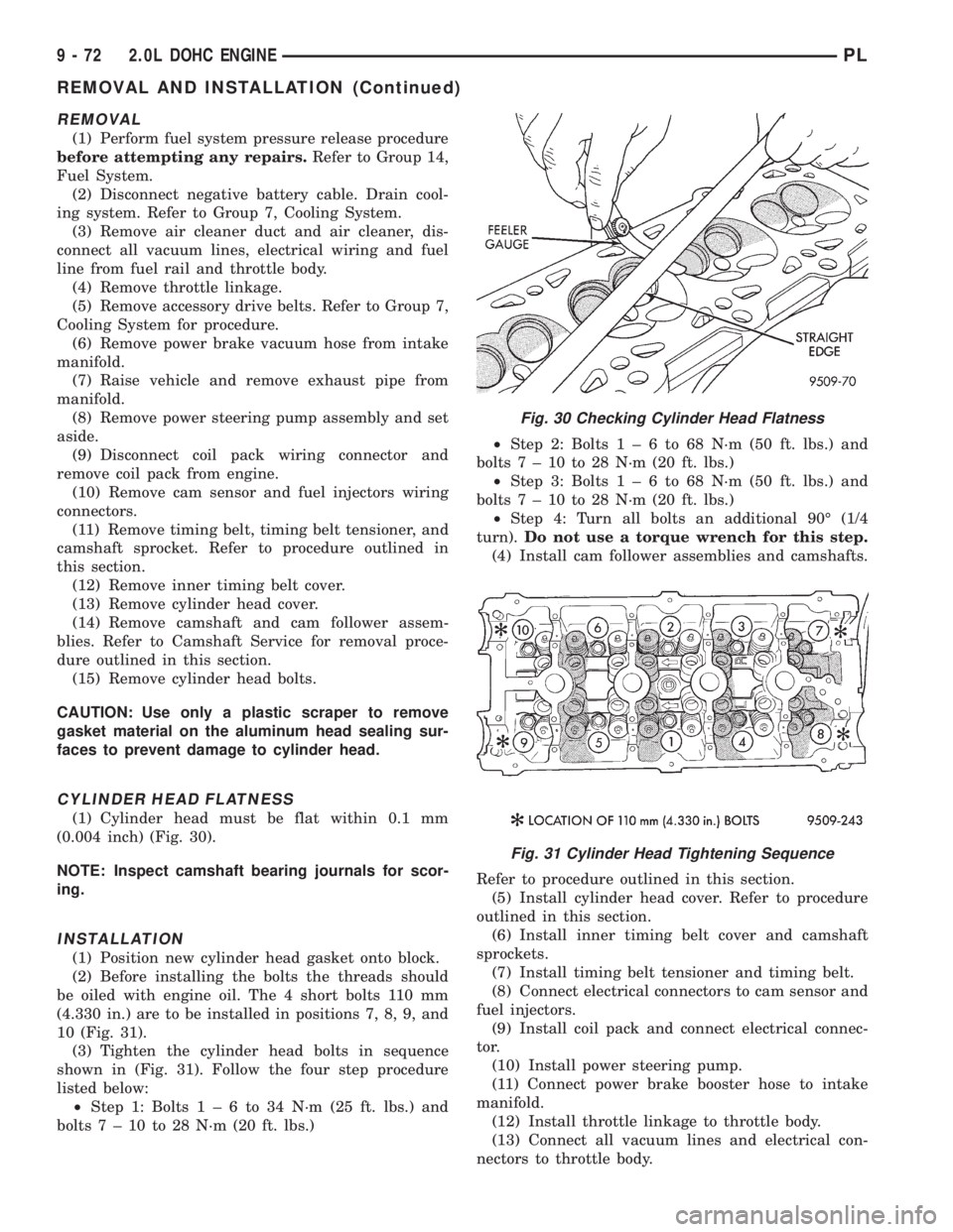
CYLINDER HEAD FLATNESS
(1) Cylinder head must be flat within 0.1 mm
(0.004 inch) (Fig. 30).
NOTE: Inspect camshaft bearing journals for scor-
ing.
INSTALLATION
(1) Position new cylinder head gasket onto block.
(2) Before installing the bolts the threads should
be oiled with engine oil. The 4 short bolts 110 mm
(4.330 in.) are to be installed in positions 7, 8, 9, and
10 (Fig. 31).
(3) Tighten the cylinder head bolts in sequence
shown in (Fig. 31). Follow the four step procedure
listed below:
²Step 1: Bolts1±6to34N´m(25ft.lbs.) and
bolts7±10to28N´m(20ft.lbs.)²Step 2: Bolts1±6to68N´m(50ft.lbs.) and
bolts7±10to28N´m(20ft.lbs.)
²Step 3: Bolts1±6to68N´m(50ft.lbs.) and
bolts7±10to28N´m(20ft.lbs.)
²Step 4: Turn all bolts an additional 90É (1/4
turn).Do not use a torque wrench for this step.
(4) Install cam follower assemblies and camshafts.
Refer to procedure outlined in this section.
(5) Install cylinder head cover. Refer to procedure
outlined in this section.
(6) Install inner timing belt cover and camshaft
sprockets.
(7) Install timing belt tensioner and timing belt.
(8) Connect electrical connectors to cam sensor and
fuel injectors.
(9) Install coil pack and connect electrical connec-
tor.
(10) Install power steering pump.
(11) Connect power brake booster hose to intake
manifold.
(12) Install throttle linkage to throttle body.
(13) Connect all vacuum lines and electrical con-
nectors to throttle body.
Fig. 30 Checking Cylinder Head Flatness
Fig. 31 Cylinder Head Tightening Sequence
9 - 72 2.0L DOHC ENGINEPL
REMOVAL AND INSTALLATION (Continued)
Page 789 of 1200
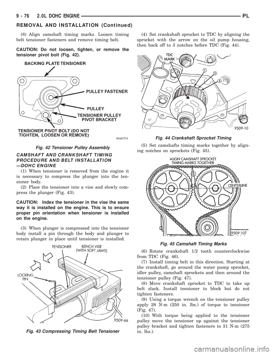
(8) Align camshaft timing marks. Loosen timing
belt tensioner fasteners and remove timing belt.
CAUTION: Do not loosen, tighten, or remove the
tensioner pivot bolt (Fig. 42).
CAMSHAFT AND CRANKSHAFT TIMING
PROCEDURE AND BELT INSTALLATION
ÐDOHC ENGINE
(1) When tensioner is removed from the engine it
is necessary to compress the plunger into the ten-
sioner body.
(2) Place the tensioner into a vise and slowly com-
press the plunger (Fig. 43).
CAUTION: Index the tensioner in the vise the same
way it is installed on the engine. This is to ensure
proper pin orientation when tensioner is installed
on the engine.
(3) When plunger is compressed into the tensioner
body install a pin through the body and plunger to
retain plunger in place until tensioner is installed.(4) Set crankshaft sprocket to TDC by aligning the
sprocket with the arrow on the oil pump housing,
then back off to 3 notches before TDC (Fig. 44).
(5) Set camshafts timing marks together by align-
ing notches on sprockets (Fig. 45).
(6) Rotate crankshaft 1/2 tooth counterclockwise
from TDC (Fig. 46).
(7) Install timing belt in this direction. Starting at
the crankshaft, go around the water pump sprocket,
idler pulley, camshaft sprockets and then around the
tensioner pulley (Fig. 47).
(8) Move crankshaft sprocket to TDC to take up
belt slack. Install tensioner to block but do not
tighten fasteners.
(9) Using a torque wrench on the tensioner pulley
apply 28 N´m (250 in. lbs.) of torque to tensioner
(Fig. 47).
(10) With torque being applied to the tensioner
pulley move the tensioner up against the tensioner
pulley bracket and tighten fasteners to 31 N´m (275
in. lbs.).
Fig. 42 Tensioner Pulley Assembly
Fig. 43 Compressing Timing Belt Tensioner
Fig. 44 Crankshaft Sprocket Timing
Fig. 45 Camshaft Timing Marks
9 - 76 2.0L DOHC ENGINEPL
REMOVAL AND INSTALLATION (Continued)
Page 792 of 1200
CAUTION: Align camshaft and crankshaft timing
marks before removing the timing belt by rotating
the engine with the crankshaft. Do not rotate the
camshaft once the timing belt has been removed as
damage to valve components may occur.
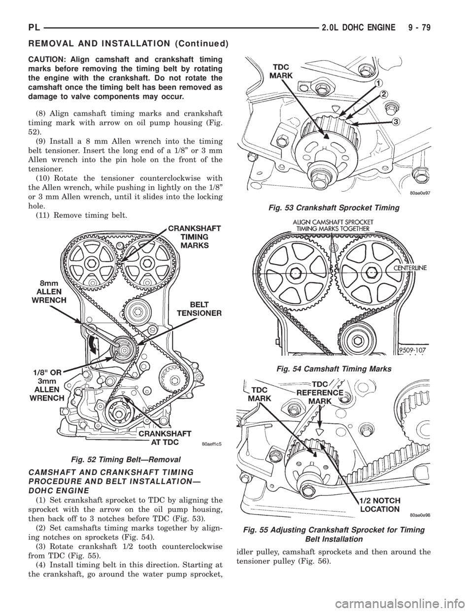
(8) Align camshaft timing marks and crankshaft
timing mark with arrow on oil pump housing (Fig.
52).
(9) Installa8mmAllen wrench into the timing
belt tensioner. Insert the long end of a 1/8º or 3 mm
Allen wrench into the pin hole on the front of the
tensioner.
(10) Rotate the tensioner counterclockwise with
the Allen wrench, while pushing in lightly on the 1/8º
or 3 mm Allen wrench, until it slides into the locking
hole.
(11) Remove timing belt.
CAMSHAFT AND CRANKSHAFT TIMING
PROCEDURE AND BELT INSTALLATIONÐ
DOHC ENGINE
(1) Set crankshaft sprocket to TDC by aligning the
sprocket with the arrow on the oil pump housing,
then back off to 3 notches before TDC (Fig. 53).
(2) Set camshafts timing marks together by align-
ing notches on sprockets (Fig. 54).
(3) Rotate crankshaft 1/2 tooth counterclockwise
from TDC (Fig. 55).
(4) Install timing belt in this direction. Starting at
the crankshaft, go around the water pump sprocket,idler pulley, camshaft sprockets and then around the
tensioner pulley (Fig. 56).
Fig. 52 Timing BeltÐRemoval
Fig. 53 Crankshaft Sprocket Timing
Fig. 54 Camshaft Timing Marks
Fig. 55 Adjusting Crankshaft Sprocket for Timing
Belt Installation
PL2.0L DOHC ENGINE 9 - 79
REMOVAL AND INSTALLATION (Continued)