1999 DODGE NEON engine oil
[x] Cancel search: engine oilPage 1001 of 1200
(8) Recheck fluid level after transaxle is at normal
operating temperature. The level should be in the
HOT region.
ALUMINUM THREAD REPAIR
Damaged or worn threads in the aluminum tran-
saxle case and valve body can be repaired by the use
of Heli-Coils. This repair consists of drilling out the
worn-out or damaged threads. Then tap the hole with
a Heli-Coil tap, and install a Heli-Coil insert into the
hole. This brings the hole back to its original thread
size.
Heli-Coil tools and inserts are readily available
from most automotive parts suppliers.
FLUSHING COOLERS AND TUBES
When a transaxle failure has contaminated the
fluid, the oil cooler(s) must be flushed. The cooler
bypass valve in the transaxle must be replaced also.
The torque converter must also be replaced with an
exchange unit. This will ensure that metal particles
or sludged oil are not later transferred back into the
reconditioned (or replaced) transaxle.
The recommended procedure for flushing the cool-
ers and tubes is to use Tool 6906A Cooler Flusher.
WARNING: WEAR PROTECTIVE EYEWEAR THAT
MEETS THE REQUIREMENTS OF OSHA AND ANSI
Z87.1±1968. WEAR STANDARD INDUSTRIAL RUB-
BER GLOVES.
KEEP LIGHTED CIGARETTES, SPARKS, FLAMES,
AND OTHER IGNITION SOURCES AWAY FROM THE
AREA TO PREVENT THE IGNITION OF COMBUSTI-
BLE LIQUIDS AND GASES. KEEP A CLASS (B) FIRE
EXTINGUISHER IN THE AREA WHERE THE
FLUSHER WILL BE USED.
KEEP THE AREA WELL VENTILATED.
DO NOT LET FLUSHING SOLVENT COME IN CON-
TACT WITH YOUR EYES OR SKIN: IF EYE CONTAM-
INATION OCCURS, FLUSH EYES WITH WATER FOR
15 TO 20 SECONDS. REMOVE CONTAMINATED
CLOTHING AND WASH AFFECTED SKIN WITH
SOAP AND WATER. SEEK MEDICAL ATTENTION.
COOLER FLUSH USING TOOL 6906A
(1) Remove cover plate filler plug on Tool 6906A.
Fill reservoir 1/2 to 3/4 full of fresh flushing solution.
Flushing solvents are petroleum based solutions gen-
erally used to clean automatic transmission compo-
nents.DO NOTuse solvents containing acids, water,
gasoline, or any other corrosive liquids.
(2) Reinstall filler plug on Tool 6906A.
(3) Verify pump power switch is turned OFF. Con-
nect red alligator clip to positive (+) battery post.
Connect black (-) alligator clip to a good ground.
(4) Disconnect the cooler lines at the transmission.NOTE: When flushing transmission cooler and
lines, ALWAYS reverse flush.
(5) Connect the BLUE pressure line to the OUT-
LET (From) cooler line.
(6) Connect the CLEAR return line to the INLET
(To) cooler line
(7) Turn pump ON for two to three minutes to
flush cooler(s) and lines. Monitor pressure readings
and clear return lines. Pressure readings should sta-
bilize below 20 psi. for vehicles equipped with a sin-
gle cooler and 30 psi. for vehicles equipped with dual
coolers. If flow is intermittent or exceeds these pres-
sures, replace cooler.
(8) Turn pump OFF.
(9) Disconnect CLEAR suction line from reservoir
at cover plate. Disconnect CLEAR return line at
cover plate, and place it in a drain pan.
(10) Turn pump ON for 30 seconds to purge flush-
ing solution from cooler and lines. Turn pump OFF.
(11) Place CLEAR suction line into a one quart
container of Mopar ATF Plus 3ttype 7176 automatic
transmission fluid.
(12) Turn pump ON until all transmission fluid is
removed from the one quart container and lines. This
purges any residual cleaning solvent from the trans-
mission cooler and lines. Turn pump OFF.
(13) Disconnect alligator clips from battery. Recon-
nect flusher lines to cover plate, and remove flushing
adapters from cooler lines.
OIL PUMP VOLUME CHECK
After the new or repaired transmission has been
installed, fill to the proper level with Mopar ATF
PLUS 3 (Type 7176) automatic transmission fluid.
The volume should be checked using the following
procedure:
(1) Disconnect theFrom coolerline at the trans-
mission and place a collecting container under the
disconnected line.
CAUTION: With the fluid set at the proper level,
fluid collection should not exceed (1) quart or inter-
nal damage to the transmission may occur.
(2) Run the engineat curb idle speed, with the
shift selector in neutral.
(3) If fluid flow is intermittent or it takes more
than 20 seconds to collect one quart of ATF, discon-
nect theTo Coolerline at the transaxle.
(4) Refill the transaxle to proper level and recheck
pump volume.
(5) If flow is found to be within acceptable limits,
replace the cooler. Then fill transmission to the
proper level, using Mopar ATF PLUS 3 (Type 7176)
automatic transmission fluid.
21 - 58 TRANSAXLEPL
SERVICE PROCEDURES (Continued)
Page 1007 of 1200
VEHICLE SPEED SENSOR PINION GEAR
When the sensor is removed for any reason, a
NEW O-ring must be installed on its outside diame-
ter.
REMOVAL
(1) Remove harness connector from sensor. Be sure
weather seal stays on harness connector.
(2) Remove bolt securing the sensor in the exten-
sion housing.
(3) Carefully pull sensor and pinion gear assembly
out of extension housing.
(4) Remove pinion gear from sensor.
INSTALLATION
(1) To install, reverse the above procedure. Be sure
extension housing and sensor flange are clean prior
to installation. Always use a NEW sensor O-ring.
(2) Tighten bolt to 7 N´m (60 in. lbs.). Tighten
speedometer cable to 4 N´m (35 in. lbs.).
PARK/NEUTRAL STARTING AND BACK-UP LAMP
SWITCH
TEST
The park/neutral starting switch is the center ter-
minal of the three terminal switch. It provides
ground for the starter solenoid circuit through the
selector lever in PARK and NEUTRAL positions only.
(1) To test switch, remove wiring connector from
switch and test for continuity between center pin of
switch and transaxle case. Continuity should exist
only when transaxle is in PARK or NEUTRAL.
(2) Check gearshift cable adjustment before replac-
ing a switch that tests bad.
REMOVAL
(1) Unscrew switch from transaxle case allowing
fluid to drain into a container. Move selector lever to
PARK, then to NEUTRAL position, and inspect to see
the switch operating lever fingers are centered in
switch opening.
INSTALLATION
(1) Screw the switch with a new seal into tran-
saxle case and tighten to 33 N´m (24 ft. lbs.). Retest
switch with the test lamp.
(2) Add fluid to transaxle to bring up to proper
level.
(3) The back-up lamp switch circuit is through the
two outside terminals of the three terminal switch.
(4) To test switch, remove wiring connector from
switch and test for continuity between the two out-
side pins.
(5) Continuity should exist only with transaxle in
REVERSE position.(6) No continuity should exist from either pin to
the case.
TRANSAXLE
REMOVAL
NOTE: The transaxle can be removed from the
vehicle without having to remove the engine.
The transaxle and torque converter must be
removed as an assembly; otherwise, the torque con-
verter drive plate, pump bushing, or oil seal may be
damaged. The drive plate will not support a load;
therefore, none of the weight of the transaxle should
be allowed to rest on the plate during removal.
All transaxle components are serviced with the
transaxle out of the vehicle. The components that are
serviceable in the vehicle are:
²Axle shaft seals
²Back±up lamp switch
²End plate
²Extension housing
²Neutral safety switch
²Shift lever
²Transaxle oil pan
²Valve Body
²Vehicle speed sensor
(1) Disconnect the battery.
(2) Pull Power Distribution Center up and out of
its holding bracket. Set Power Distribution Center
aside to gain clearance.
(3) Remove battery heat shield and remove battery
from engine compartment. Remove battery tray from
engine compartment. Disconnect cruise control (if
equipped).
(4) Remove vehicle speed sensor wiring.
(5) Disconnect neutral safety switch and torque
converter control wiring at transaxle.
CAUTION: Pry up with equal force on both sides of
shifter cable isolator bushing to avoid damaging
cable isolator bushing.
(6) Disconnect gear shift cable end from transaxle
shift lever (Fig. 22). Remove bracket bolt at transaxle
(Fig. 23).
(7) Remove throttle pressure control cable from
lever. Then remove bracket bolts at the transaxle
(Fig. 24).
(8) Remove dipstick tube.
(9) Remove transaxle cooler lines and plug lines
(Fig. 25).
(10) Remove throttle pressure control cable sup-
port bracket bolts. Remove upper bellhousing bolts
and upper starter bolt (Fig. 26).
21 - 64 TRANSAXLEPL
REMOVAL AND INSTALLATION (Continued)
Page 1010 of 1200
PUMP OIL SEAL
The pump oil seal can be replaced without remov-
ing the pump and reaction shaft support assembly
from the transaxle case.
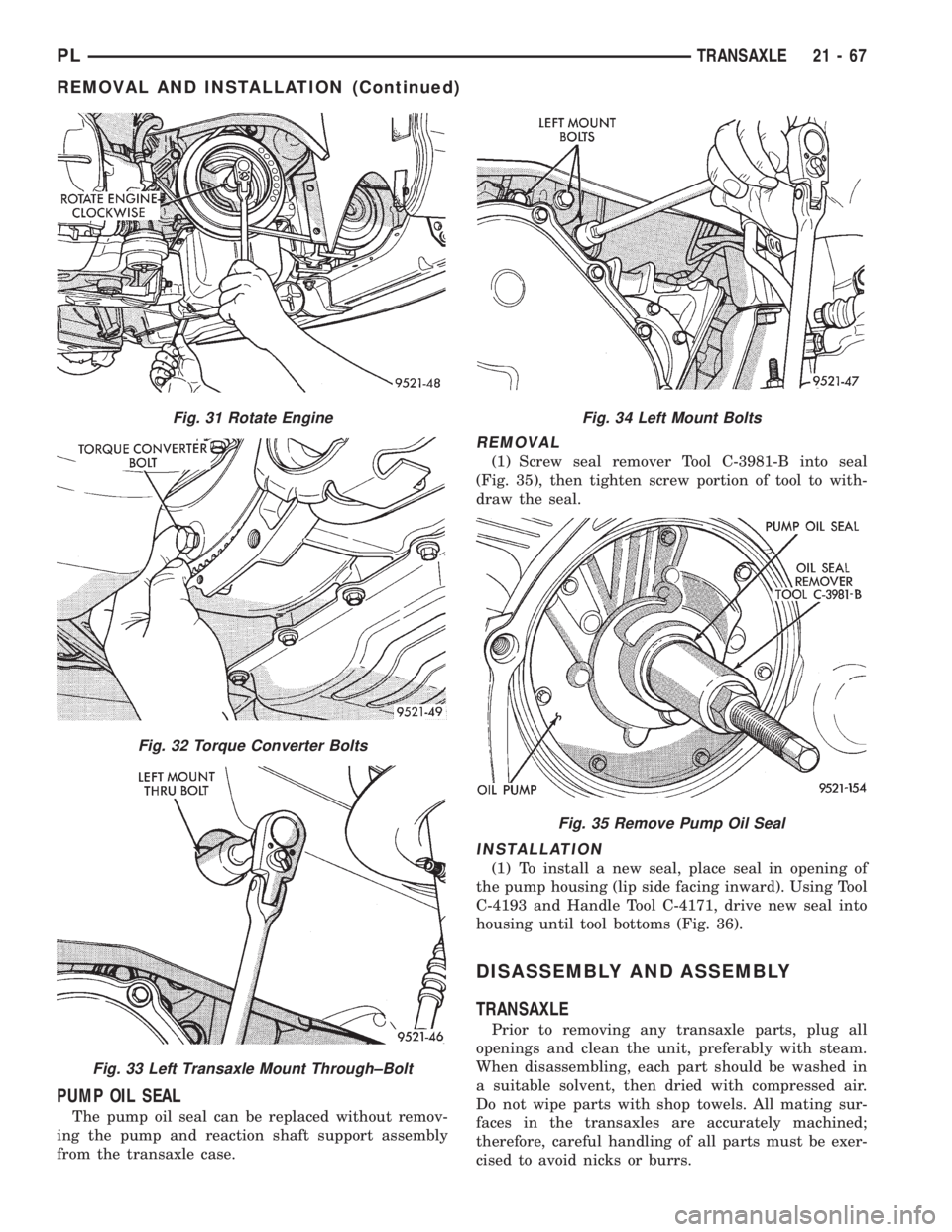
REMOVAL
(1) Screw seal remover Tool C-3981-B into seal
(Fig. 35), then tighten screw portion of tool to with-
draw the seal.
INSTALLATION
(1) To install a new seal, place seal in opening of
the pump housing (lip side facing inward). Using Tool
C-4193 and Handle Tool C-4171, drive new seal into
housing until tool bottoms (Fig. 36).
DISASSEMBLY AND ASSEMBLY
TRANSAXLE
Prior to removing any transaxle parts, plug all
openings and clean the unit, preferably with steam.
When disassembling, each part should be washed in
a suitable solvent, then dried with compressed air.
Do not wipe parts with shop towels. All mating sur-
faces in the transaxles are accurately machined;
therefore, careful handling of all parts must be exer-
cised to avoid nicks or burrs.
Fig. 31 Rotate Engine
Fig. 32 Torque Converter Bolts
Fig. 33 Left Transaxle Mount Through±Bolt
Fig. 34 Left Mount Bolts
Fig. 35 Remove Pump Oil Seal
PLTRANSAXLE 21 - 67
REMOVAL AND INSTALLATION (Continued)
Page 1120 of 1200
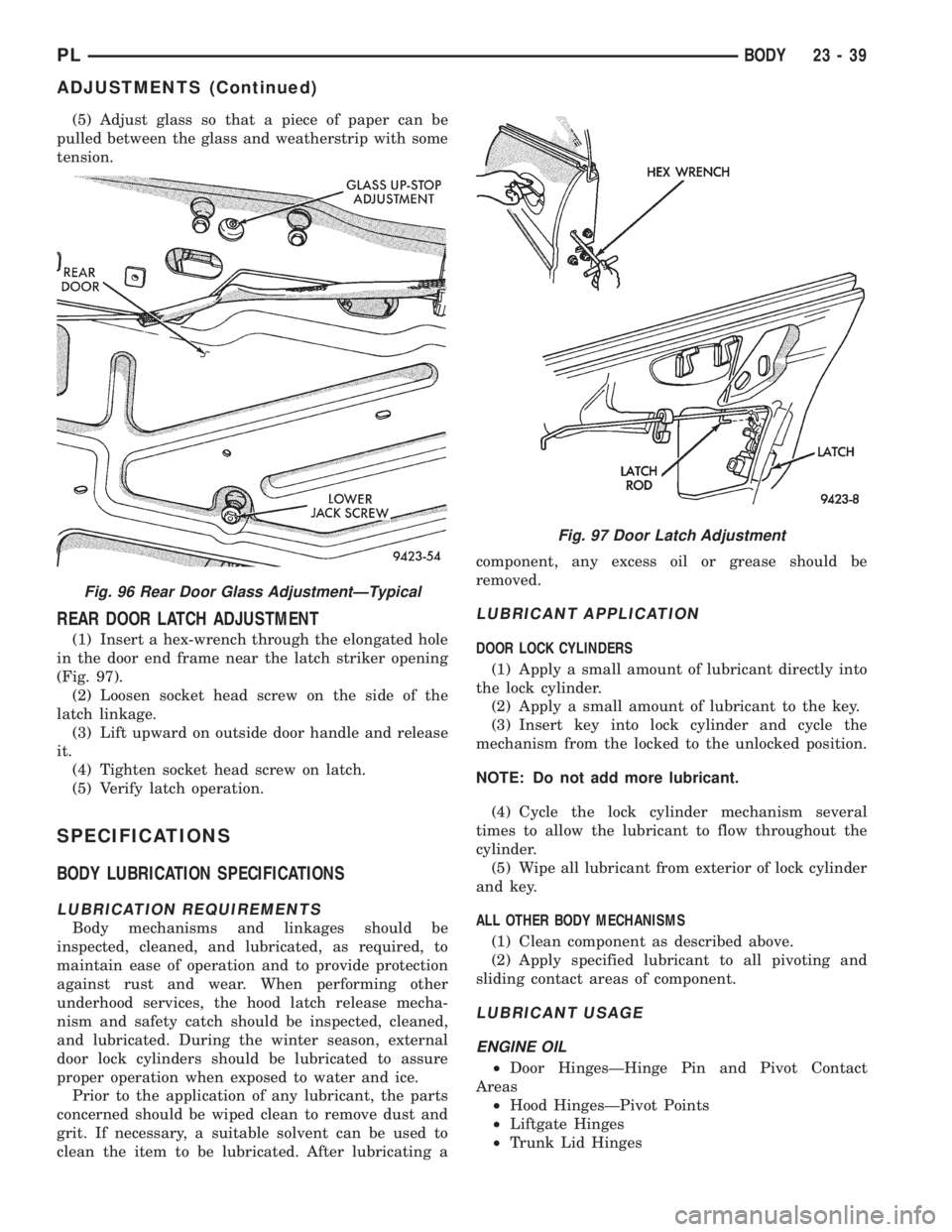
(5) Adjust glass so that a piece of paper can be
pulled between the glass and weatherstrip with some
tension.
REAR DOOR LATCH ADJUSTMENT
(1) Insert a hex-wrench through the elongated hole
in the door end frame near the latch striker opening
(Fig. 97).
(2) Loosen socket head screw on the side of the
latch linkage.
(3) Lift upward on outside door handle and release
it.
(4) Tighten socket head screw on latch.
(5) Verify latch operation.
SPECIFICATIONS
BODY LUBRICATION SPECIFICATIONS
LUBRICATION REQUIREMENTS
Body mechanisms and linkages should be
inspected, cleaned, and lubricated, as required, to
maintain ease of operation and to provide protection
against rust and wear. When performing other
underhood services, the hood latch release mecha-
nism and safety catch should be inspected, cleaned,
and lubricated. During the winter season, external
door lock cylinders should be lubricated to assure
proper operation when exposed to water and ice.
Prior to the application of any lubricant, the parts
concerned should be wiped clean to remove dust and
grit. If necessary, a suitable solvent can be used to
clean the item to be lubricated. After lubricating acomponent, any excess oil or grease should be
removed.
LUBRICANT APPLICATION
DOOR LOCK CYLINDERS
(1) Apply a small amount of lubricant directly into
the lock cylinder.
(2) Apply a small amount of lubricant to the key.
(3) Insert key into lock cylinder and cycle the
mechanism from the locked to the unlocked position.
NOTE: Do not add more lubricant.
(4) Cycle the lock cylinder mechanism several
times to allow the lubricant to flow throughout the
cylinder.
(5) Wipe all lubricant from exterior of lock cylinder
and key.
ALL OTHER BODY MECHANISMS
(1) Clean component as described above.
(2) Apply specified lubricant to all pivoting and
sliding contact areas of component.
LUBRICANT USAGE
ENGINE OIL
²Door HingesÐHinge Pin and Pivot Contact
Areas
²Hood HingesÐPivot Points
²Liftgate Hinges
²Trunk Lid Hinges
Fig. 96 Rear Door Glass AdjustmentÐTypical
Fig. 97 Door Latch Adjustment
PLBODY 23 - 39
ADJUSTMENTS (Continued)
Page 1122 of 1200
PAINT
INDEX
page page
GENERAL INFORMATION
AFTERMARKET PAINT REPAIR PRODUCTS . . . 42
BASE COAT/CLEAR COAT FINISH........... 41PAINT CODE........................... 41
PAINTED SURFACE TOUCH-UP............ 41
WET SANDING, BUFFING, AND POLISHING . . . 41
GENERAL INFORMATION
PAINT CODE
A paint code is provided on the body code plate
located in the engine compartment. Refer to the
Introduction section at the front of this manual for
body code plate description. The paint and trim codes
are also included on the Vehicle Safety Label located
on the driver's door end frame.
BASE COAT/CLEAR COAT FINISH
On most vehicles a two-part paint application (base
coat/clear coat) is used. Color paint that is applied to
primer is called base coat. The clear coat protects the
base coat from ultraviolet light and provides a dura-
ble high-gloss finish.
WET SANDING, BUFFING, AND POLISHING
Minor acid etching, orange peel, or smudging in
clear coat or single-stage finishes can be reduced
with light wet sanding, hand buffing, and polishing.
If the finish has been wet sanded in the past, it
cannot be repeated. Wet sanding operation
should be performed by a trained automotive
paint technician.
CAUTION: Do not remove clear coat finish, if
equipped. Base coat paint must retain clear coat for
durability.
PAINTED SURFACE TOUCH-UP
When a painted metal surface has been scratched
or chipped, it should be touched-up as soon as possi-ble to avoid corrosion. For best results, use Mopart
Scratch Filler/Primer, Touch-Up Paints and Clear Top
Coat. Refer to Introduction group of this manual for
Body Code Plate information.
TOUCH-UP PROCEDURE
(1) Scrape loose paint and corrosion from inside
scratch or chip.
(2) Clean affected area with MopartTar/Road Oil
Remover, and allow to dry.
(3) Fill the inside of the scratch or chip with a coat
of filler/primer. Do not overlap primer onto good sur-
face finish. The applicator brush should be wet
enough to puddle-fill the defect without running. Do
not stroke brush applicator on body surface. Allow
the filler/primer to dry hard.
(4) Cover the filler/primer with color touch-up
paint. Do not overlap touch-up color onto the original
color coat around the scratch or chip. Butt the new
color to the original color, if possible. Do not stroke
applicator brush on body surface. Allow touch-up
paint to dry hard.
(5) On vehicles without clear coat, the touch-up
color can be lightly wet sanded (1500 grit) and pol-
ished with rubbing compound.
(6) On vehicles with clear coat, apply clear top coat
to touch-up paint with the same technique as
described in Step 4. Allow clear top coat to dry hard.
If desired, Step 5 can be performed on clear top coat.
PLBODY 23 - 41
Page 1134 of 1200
HEATING AND AIR CONDITIONING
CONTENTS
page page
GENERAL INFORMATION
INTRODUCTION......................... 2
SAFETY PRECAUTIONS AND WARNINGS..... 2
DESCRIPTION AND OPERATION
A/C REFRIGERANT LINES................. 3
BLOWER MOTOR RESISTOR............... 3
COMPRESSOR FRONT SHAFT SEAL......... 4
COMPRESSOR.......................... 4
CONDENSATION DRAIN TUBE.............. 4
ENGINE COOLING SSTEM
REQUIREMENTS....................... 4
EVAPORATOR PROBE..................... 4
HANDLING TUBING AND FITTINGS.......... 4
HIGH PRESSURE CUT OUT SWITCH......... 5
LOW PRESSURE CUT OFF SWITCH......... 5
SIDE WINDOW DEMISTERS............... 5
SYSTEM AIRFLOW....................... 5
SYSTEM OIL LEVEL...................... 6
VACUUM CONTROL SYSTEM............... 6
DIAGNOSIS AND TESTING
A/C PERFORMANCE TEST................. 6
BLOWER MOTOR ELECTRICAL DIAGNOSIS . . . 8
BLOWER MOTOR VIBRATION
AND/OR NOISE DIAGNOSIS.............. 8
COMPRESSOR NOISE DIAGNOSIS.......... 7
EVAPORATOR PROBE TEST................ 8
EXPANSION VALVE....................... 7
HEATER PERFORMANCE TEST............. 8
LOW PRESSURE CUT-OFF SWITCH......... 11
SYSTEM CHARGE LEVEL TEST............ 11
VACUUM CONTROL SYSTEM.............. 12
SERVICE PROCEDURES
CHARGING A/C SYSTEM................. 14
EVACUATING REFRIGERANT SYSTEM....... 15R-134a REFRIGERANT................... 16
SERVICING REFRIGERANT OIL LEVEL...... 17
SYSTEM LEAK CHECKING................ 17
REMOVAL AND INSTALLATION
A/C FILTER/DRIER...................... 23
A/C SERVICE PORT VALVE CORES......... 18
BLOWER MOTOR AND WHEEL ASSEMBLY . . . 18
BLOWER MOTOR RESISTOR.............. 18
BLOWER MOTOR WHEEL................ 19
COMPRESSOR CLUTCH/COIL ASSEMBLY.... 19
COMPRESSOR......................... 19
CONDENSATION DRAIN TUBE............ 21
CONDENSER........................... 21
DISCHARGE LINE....................... 21
EVAPORATOR PROBE.................... 22
EVAPORATOR.......................... 21
EXPANSION VALVE...................... 23
HEATER CORE......................... 24
HEATER HOSES........................ 24
HIGH PRESSURE CUT OUT SWITCH........ 23
HIGH PRESSURE RELIEF VALVE........... 24
LIQUID LINE........................... 25
LOW PRESSURE CUT OFF SWITCH........ 25
MODE CONTROL CABLE................. 25
RECIRCULATION DOOR ACTUATOR........ 26
SUCTION LINE......................... 27
TEMPERATURE CONTROL CABLE.......... 27
UNIT HOUSING......................... 27
DISASSEMBLY AND ASSEMBLY
AIR DISTRIBUTION MODULE ±
RECONDITION........................ 28
ADJUSTMENTS
MODE CONTROL CABLE................. 30
TEMPERATURE CONTROL CABLE.......... 30
PLHEATING AND AIR CONDITIONING 24 - 1
Page 1137 of 1200
COMPRESSOR
The compressor used on this vehicle is a Nippon-
denso 10PA17 R-134a. This compressor uses an alu-
minum swash plate, teflon coated pistons and
aluminum sleeved cylinder walls.
CAUTION: A 10PA17 R-12 compressor looks identi-
cal to a 10PA17 R-134a and will bolt up to the vehi-
cle. The 10PA17 R-12 compressor must not be used
on this system. It is extremely important that a
10PA17 R-134a compressor is identified prior to
using compressor in question. Check tag located
on compressor for model number.
NOISE
Excessive noise that occurs when the air condition-
ing is being used may be caused by:
²Loose bolts
²Mounting brackets
²Loose compressor clutch
²Excessive high refrigerant operating pressure
Verify the following before compressor repair is
performed:
(1) Compressor drive belt condition
(2) Proper refrigerant charge
(3) Thermal expansion valve (TXV) operating cor-
rectly
(4) Head pressure is normal
COMPRESSOR FRONT SHAFT SEAL
The compressor front shaft seal is not serviceable.
If a leak is detected at the shaft seal, the compressor
must be replaced as a unit.
CONDENSATION DRAIN TUBE
Condensation that accumulates in the evaporator
housing is drained from a tube through the dash and
on to the ground. This tube must be kept open to
prevent condensate water from collecting in the bot-
tom of the housing.
The tapered end of the drain tube is designed to
keep contaminants from entering the heater A/C unit
housing. If the tube is pinched or blocked, condensate
cannot drain, causing water to back up and spill into
the passenger compartment. It is normal to see con-
densate drainage below the vehicle. If the tube is
damaged, it should be replaced.
ENGINE COOLING SYSTEM REQUIREMENTS
To maintain ample temperature levels from the
heating-A/C system, the cooling system must be in
proper working order. Refer to Group 0, Lubrication
and Maintenance or Group 7, Cooling System of this
manual.
The use of a bug screen is not recommended. Any
obstructions forward of the condenser can reduce the
effectiveness of the air conditioning system.
EVAPORATOR PROBE
The evaporator probe can be replaced without hav-
ing to remove the unit housing from the vehicle.
The evaporator probe is located in the unit housing
and placed in the evaporator fins. The probe prevents
evaporator freeze-up. This is done by cycling the com-
pressor clutch OFF when evaporator temperature
drops below freeze point. It cycles ON when the
evaporator temperature rises above freeze point. The
evaporator probe uses a thermistor probe in a capil-
lary tube. The tube is inserted between the evapora-
tor fins in the heater-A/C unit housing.
HANDLING TUBING AND FITTINGS
Kinks in the refrigerant tubing or sharp bends in
the refrigerant hose lines will greatly reduce the
capacity of the entire system. High pressures are pro-
duced in the system when it is operating. Extreme
care must be exercised to make sure that all connec-
tions are pressure tight. Dirt and moisture can enter
the system when it is opened for repair or replace-
ment of lines or components. The refrigerant oil will
absorb moisture readily out of the air. This moisture
will convert into acids within a closed system.
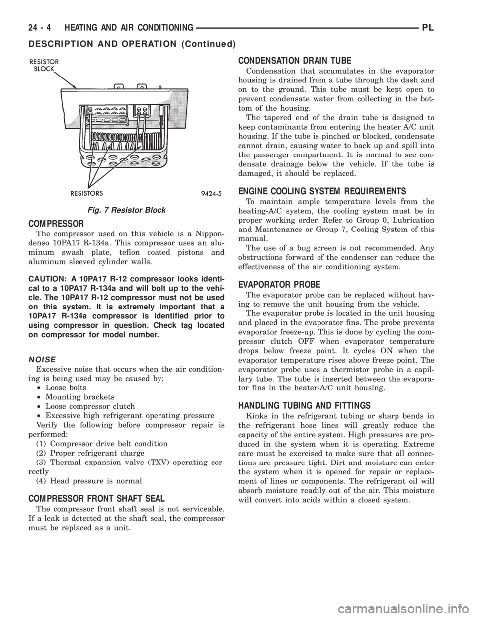
Fig. 7 Resistor Block
24 - 4 HEATING AND AIR CONDITIONINGPL
DESCRIPTION AND OPERATION (Continued)
Page 1140 of 1200
perature in test room and on vehicle must be 21É C
(70ÉF) minimum for this test.
NOTE: When connecting the service equipment
coupling to the line fitting, verify that the valve of
the coupling is fully closed. This will reduce the
amount of effort required to make the connection.
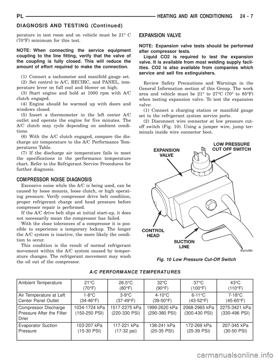
(1) Connect a tachometer and manifold gauge set.
(2) Set control to A/C, RECIRC, and PANEL, tem-
perature lever on full cool and blower on high.
(3) Start engine and hold at 1000 rpm with A/C
clutch engaged.
(4) Engine should be warmed up with doors and
windows closed.
(5) Insert a thermometer in the left center A/C
outlet and operate the engine for five minutes. The
A/C clutch may cycle depending on ambient condi-
tions.
(6) With the A/C clutch engaged, compare the dis-
charge air temperature to the A/C Performance Tem-
peratures Table.
(7) If the discharge air temperature fails to meet
the specifications in the performance temperature
chart. Refer to the Refrigerant Service Procedures for
further diagnosis.
COMPRESSOR NOISE DIAGNOSIS
Excessive noise while the A/C is being used, can be
caused by loose mounts, loose clutch, or high operat-
ing pressure. Verify compressor drive belt condition,
proper refrigerant charge and head pressure before
compressor repair is performed.
If the A/C drive belt slips at initial start-up, it does
not necessarily mean the compressor has failed.
With the close tolerances of a compressor it is pos-
sible to experience a temporary lockup. The longer
the A/C system is inactive, the more likely the condi-
tion to occur.
This condition is the result of normal refrigerant
movement within the A/C system caused by temper-
ature changes. The refrigerant movement may wash
the oil out of the compressor.
EXPANSION VALVE
NOTE: Expansion valve tests should be performed
after compressor tests.
Liquid CO2 is required to test the expansion
valve. It is available from most welding supply facil-
ities. CO2 is also available from companies which
service and sell fire extinguishers.
Review Safety Precautions and Warnings in the
General Information section of this Group. The work
area and vehicle must be 21É to 27ÉC (70É to 85ÉF)
when testing expansion valve. To test the expansion
valve:
(1) Connect a charging station or manifold gauge
set to the refrigerant system service ports.
(2) Disconnect wire connector at low pressure cut-
off switch (Fig. 10). Using a jumper wire, jump ter-
minals inside wire connector boot.
A/C PERFORMANCE TEMPERATURES
Ambient Temperature 21ÉC
(70ÉF)26.5ÉC
(80ÉF)32ÉC
(90ÉF)37ÉC
(100ÉF)43ÉC
(110ÉF)
Air Temperature at Left
Center Panel Outlet1-8ÉC
(34-46ÉF)3-9ÉC
(37-49ÉF)4-10ÉC
(39-50ÉF)6-11ÉC
(43-52ÉF)7-18ÉC
(45-65ÉF)
Compressor Discharge
Pressure After the Filter
Drier1034-1724 kPa
(150-250 PSI)1517-2275 kPa
(220-330 PSI)1999-2620 kPa
(290-380 PSI)2068-2965 kPa
(300-430 PSI)2275-3421 kPa
(330-496 PSI)
Evaporator Suction
Pressure103-207 kPa
(15-30 PSI)117-221 kPa
(17-32 psi)138-241 kPa
(20-35 PSI)172-269 kPa
(25-39 PSI)207-345 kPa
(30-50 PSI)
Fig. 10 Low Pressure Cut-Off Switch
PLHEATING AND AIR CONDITIONING 24 - 7
DIAGNOSIS AND TESTING (Continued)