1999 DODGE NEON heater
[x] Cancel search: heaterPage 1161 of 1200
(3) Using a refrigerant recovery machine, remove
the refrigerant from the A/C system, if equipped.
(4) Remove suction line at expansion valve. Place a
piece of tape over open refrigerant line to prevent
moisture and/or dirt from entering the line.
(5) Remove expansion valve from evaporator. Place
a piece of tape over open evaporator fitting to pre-
vent moisture and/or dirt from entering the evapora-
tor.
(6) Remove rubber drain tube extension from con-
densation drain tube.
(7) Remove three retaining nuts located in the
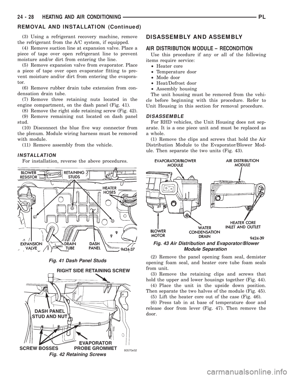
engine compartment, on the dash panel (Fig. 41).
(8) Remove the right side retaining screw (Fig. 42).
(9) Remove remaining nut located on dash panel
stud.
(10) Disconnect the blue five way connector from
the plenum. Module wiring harness must be removed
with module.
(11) Remove assembly from the vehicle.
INSTALLATION
For installation, reverse the above procedures.
DISASSEMBLY AND ASSEMBLY
AIR DISTRIBUTION MODULE ± RECONDITION
Use this procedure if any or all of the following
items require service:
²Heater core
²Temperature door
²Mode door
²Heat/Defrost door
²Assembly housing
The unit housing must be removed from the vehi-
cle before beginning with this procedure. Refer to
Unit Housing in this section for removal procedure.
DISASSEMBLE
For RHD vehicles, the Unit Housing does not sep-
arate. It is a one piece unit and must be replaced as
a whole.
(1) Remove the clips and screws that hold the Air
Distribution Module to the Evaporator/Blower Mod-
ule. Then separate the two units (Fig. 43).
(2) Remove the panel opening foam seal, demister
opening foam seal, and heater core tube foam seals
from unit.
(3) Remove the retaining clips and screws that
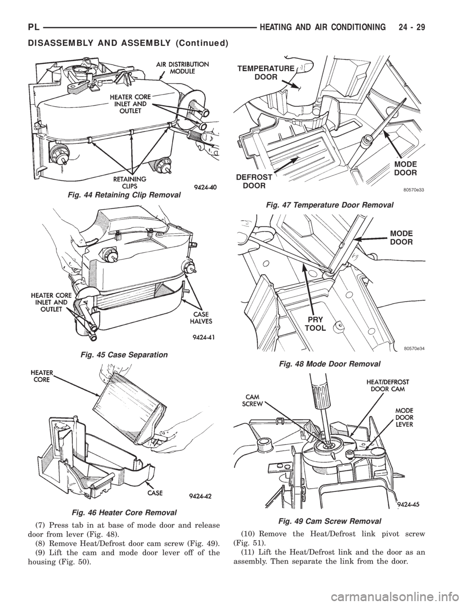
hold the upper and lower housings together (Fig. 44).
(4) Place the unit in the upside down position.
Then separate the two halves of the module (Fig. 45).
(5) Lift the heater core out of the case (Fig. 46).
(6) Press tab in at base of temperature door and
release door from lever (Fig. 47). Then remove the
door.
Fig. 41 Dash Panel Studs
Fig. 42 Retaining Screws
Fig. 43 Air Distribution and Evaporator/Blower
Module Separation
24 - 28 HEATING AND AIR CONDITIONINGPL
REMOVAL AND INSTALLATION (Continued)
Page 1162 of 1200
(7) Press tab in at base of mode door and release
door from lever (Fig. 48).
(8) Remove Heat/Defrost door cam screw (Fig. 49).
(9) Lift the cam and mode door lever off of the
housing (Fig. 50).(10) Remove the Heat/Defrost link pivot screw
(Fig. 51).
(11) Lift the Heat/Defrost link and the door as an
assembly. Then separate the link from the door.
Fig. 44 Retaining Clip Removal
Fig. 45 Case Separation
Fig. 46 Heater Core Removal
Fig. 47 Temperature Door Removal
Fig. 48 Mode Door Removal
Fig. 49 Cam Screw Removal
PLHEATING AND AIR CONDITIONING 24 - 29
DISASSEMBLY AND ASSEMBLY (Continued)
Page 1168 of 1200
HEX
CODEGENERIC
SCAN
TOOL
CODEDRB SCAN TOOL
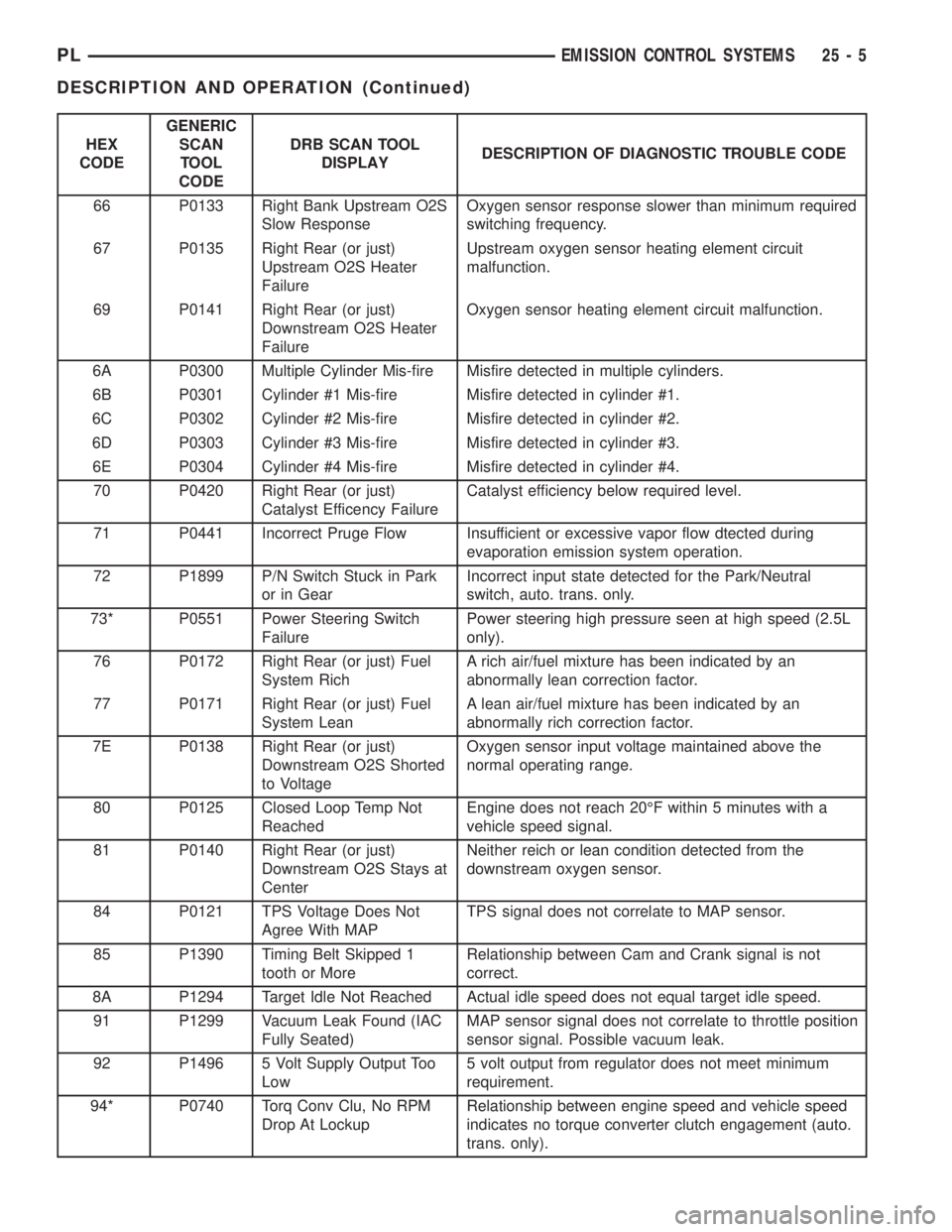
DISPLAYDESCRIPTION OF DIAGNOSTIC TROUBLE CODE
66 P0133 Right Bank Upstream O2S
Slow ResponseOxygen sensor response slower than minimum required
switching frequency.
67 P0135 Right Rear (or just)
Upstream O2S Heater
FailureUpstream oxygen sensor heating element circuit
malfunction.
69 P0141 Right Rear (or just)
Downstream O2S Heater
FailureOxygen sensor heating element circuit malfunction.
6A P0300 Multiple Cylinder Mis-fire Misfire detected in multiple cylinders.
6B P0301 Cylinder #1 Mis-fire Misfire detected in cylinder #1.
6C P0302 Cylinder #2 Mis-fire Misfire detected in cylinder #2.
6D P0303 Cylinder #3 Mis-fire Misfire detected in cylinder #3.
6E P0304 Cylinder #4 Mis-fire Misfire detected in cylinder #4.
70 P0420 Right Rear (or just)
Catalyst Efficency FailureCatalyst efficiency below required level.
71 P0441 Incorrect Pruge Flow Insufficient or excessive vapor flow dtected during
evaporation emission system operation.
72 P1899 P/N Switch Stuck in Park
or in GearIncorrect input state detected for the Park/Neutral
switch, auto. trans. only.
73* P0551 Power Steering Switch
FailurePower steering high pressure seen at high speed (2.5L
only).
76 P0172 Right Rear (or just) Fuel
System RichA rich air/fuel mixture has been indicated by an
abnormally lean correction factor.
77 P0171 Right Rear (or just) Fuel
System LeanA lean air/fuel mixture has been indicated by an
abnormally rich correction factor.
7E P0138 Right Rear (or just)
Downstream O2S Shorted
to VoltageOxygen sensor input voltage maintained above the
normal operating range.
80 P0125 Closed Loop Temp Not
ReachedEngine does not reach 20ÉF within 5 minutes with a
vehicle speed signal.
81 P0140 Right Rear (or just)
Downstream O2S Stays at
CenterNeither reich or lean condition detected from the
downstream oxygen sensor.
84 P0121 TPS Voltage Does Not
Agree With MAPTPS signal does not correlate to MAP sensor.
85 P1390 Timing Belt Skipped 1
tooth or MoreRelationship between Cam and Crank signal is not
correct.
8A P1294 Target Idle Not Reached Actual idle speed does not equal target idle speed.
91 P1299 Vacuum Leak Found (IAC
Fully Seated)MAP sensor signal does not correlate to throttle position
sensor signal. Possible vacuum leak.
92 P1496 5 Volt Supply Output Too
Low5 volt output from regulator does not meet minimum
requirement.
94* P0740 Torq Conv Clu, No RPM
Drop At LockupRelationship between engine speed and vehicle speed
indicates no torque converter clutch engagement (auto.
trans. only).
PLEMISSION CONTROL SYSTEMS 25 - 5
DESCRIPTION AND OPERATION (Continued)
Page 1169 of 1200
HEX
CODEGENERIC
SCAN
TOOL
CODEDRB SCAN TOOL
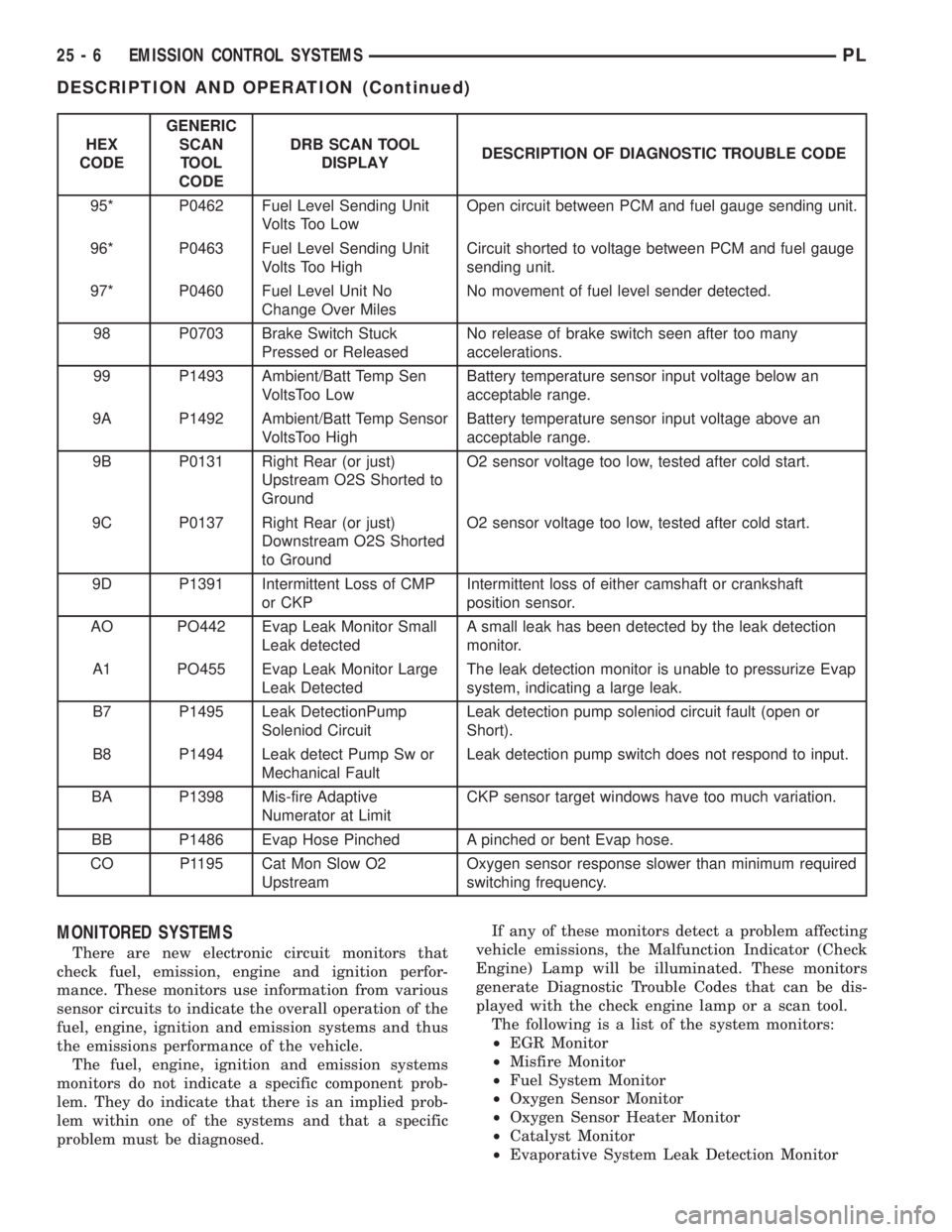
DISPLAYDESCRIPTION OF DIAGNOSTIC TROUBLE CODE
95* P0462 Fuel Level Sending Unit
Volts Too LowOpen circuit between PCM and fuel gauge sending unit.
96* P0463 Fuel Level Sending Unit
Volts Too HighCircuit shorted to voltage between PCM and fuel gauge
sending unit.
97* P0460 Fuel Level Unit No
Change Over MilesNo movement of fuel level sender detected.
98 P0703 Brake Switch Stuck
Pressed or ReleasedNo release of brake switch seen after too many
accelerations.
99 P1493 Ambient/Batt Temp Sen
VoltsToo LowBattery temperature sensor input voltage below an
acceptable range.
9A P1492 Ambient/Batt Temp Sensor
VoltsToo HighBattery temperature sensor input voltage above an
acceptable range.
9B P0131 Right Rear (or just)
Upstream O2S Shorted to
GroundO2 sensor voltage too low, tested after cold start.
9C P0137 Right Rear (or just)
Downstream O2S Shorted
to GroundO2 sensor voltage too low, tested after cold start.
9D P1391 Intermittent Loss of CMP
or CKPIntermittent loss of either camshaft or crankshaft
position sensor.
AO PO442 Evap Leak Monitor Small
Leak detectedA small leak has been detected by the leak detection
monitor.
A1 PO455 Evap Leak Monitor Large
Leak DetectedThe leak detection monitor is unable to pressurize Evap
system, indicating a large leak.
B7 P1495 Leak DetectionPump
Soleniod CircuitLeak detection pump soleniod circuit fault (open or
Short).
B8 P1494 Leak detect Pump Sw or
Mechanical FaultLeak detection pump switch does not respond to input.
BA P1398 Mis-fire Adaptive
Numerator at LimitCKP sensor target windows have too much variation.
BB P1486 Evap Hose Pinched A pinched or bent Evap hose.
CO P1195 Cat Mon Slow O2
UpstreamOxygen sensor response slower than minimum required
switching frequency.
MONITORED SYSTEMS
There are new electronic circuit monitors that
check fuel, emission, engine and ignition perfor-
mance. These monitors use information from various
sensor circuits to indicate the overall operation of the
fuel, engine, ignition and emission systems and thus
the emissions performance of the vehicle.
The fuel, engine, ignition and emission systems
monitors do not indicate a specific component prob-
lem. They do indicate that there is an implied prob-
lem within one of the systems and that a specific
problem must be diagnosed.If any of these monitors detect a problem affecting
vehicle emissions, the Malfunction Indicator (Check
Engine) Lamp will be illuminated. These monitors
generate Diagnostic Trouble Codes that can be dis-
played with the check engine lamp or a scan tool.
The following is a list of the system monitors:
²EGR Monitor
²Misfire Monitor
²Fuel System Monitor
²Oxygen Sensor Monitor
²Oxygen Sensor Heater Monitor
²Catalyst Monitor
²Evaporative System Leak Detection Monitor
25 - 6 EMISSION CONTROL SYSTEMSPL
DESCRIPTION AND OPERATION (Continued)
Page 1170 of 1200
Following is a description of each system monitor,
and its DTC.
Refer to the appropriate Powertrain Diagnos-
tics Procedures manual for diagnostic proce-
dures.
HEX 66, and 7AÐOXYGEN SENSOR (O2S)
MONITOR
Effective control of exhaust emissions is achieved
by an oxygen feedback system. The most important
element of the feedback system is the O2S. The O2S
is located in the exhaust path. Once it reaches oper-
ating temperature 300É to 350ÉC (572É to 662ÉF), the
sensor generates a voltage that is inversely propor-
tional to the amount of oxygen in the exhaust. The
information obtained by the sensor is used to calcu-
late the fuel injector pulse width. This maintains a
14.7 to 1 air fuel (A/F) ratio. At this mixture ratio,
the catalyst works best to remove hydrocarbons (HC),
carbon monoxide (CO) and nitrous oxide (NOx) from
the exhaust.
The O2S is also the main sensing element for the
EGR, Catalyst and Fuel Monitors.
The O2S may fail in any or all of the following
manners:
²Slow response rate
²Reduced output voltage
²Dynamic shift
²Shorted or open circuits
Response rate is the time required for the sensor to
switch from lean to rich once it is exposed to a richer
than optimum A/F mixture or vice versa. As the sen-
sor starts malfunctioning, it could take longer to
detect the changes in the oxygen content of the
exhaust gas.
The output voltage of the O2S ranges from 0 to 1
volt. A good sensor can easily generate any output
voltage in this range as it is exposed to different con-
centrations of oxygen. To detect a shift in the A/F
mixture (lean or rich), the output voltage has to
change beyond a threshold value. A malfunctioning
sensor could have difficulty changing beyond the
threshold value.
HEX 67, 69, 7C, and 7DÐOXYGEN SENSOR
HEATER MONITOR
If there is an oxygen sensor (O2S) DTC as well as
a O2S heater DTC, the O2S fault MUST be repaired
first. After the O2S fault is repaired, verify that the
heater circuit is operating correctly.
Effective control of exhaust emissions is achieved
by an oxygen feedback system. The most important
element of the feedback system is the O2S. The O2S
is located in the exhaust path. Once it reaches oper-
ating temperature 300É to 350ÉC (572 Éto 662ÉF), the
sensor generates a voltage that is inversely propor-
tional to the amount of oxygen in the exhaust. Theinformation obtained by the sensor is used to calcu-
late the fuel injector pulse width. This maintains a
14.7 to 1 Air Fuel (A/F) ratio. At this mixture ratio,
the catalyst works best to remove hydrocarbons (HC),
carbon monoxide (CO) and nitrogen oxide (NOx) from
the exhaust.
The voltage readings taken from the O2S are very
temperature sensitive. The readings are not accurate
below 300ÉC. Heating of the O2S is done to allow the
engine controller to shift to closed loop control as
soon as possible. The heating element used to heat
the O2S must be tested to ensure that it is heating
the sensor properly.
The O2S circuit is monitored for a drop in voltage.
The sensor output is used to test the heater by iso-
lating the effect of the heater element on the O2S
output voltage from the other effects.
HEX 2EÐEGR MONITOR
The Powertrain Control Module (PCM) performs
an on-board diagnostic check of the EGR system.
The EGR system consists of two main components:
a vacuum solenoid back pressure transducer and a
vacuum operated valve. The EGR monitor is used to
test whether the EGR system is operating within
specifications. The diagnostic check activates only
during selected engine/driving conditions. When the
conditions are met, the EGR is turned off (solenoid
energized) and the O2S compensation control is mon-
itored. Turning off the EGR shifts the air fuel (A/F)
ratio in the lean direction. The O2S data should indi-
cate an increase in the O2 concentration in the com-
bustion chamber when the exhaust gases are no
longer recirculated. While this test does not directly
measure the operation of the EGR system, it can be
inferred from the shift in the O2S data whether the
EGR system is operating correctly. Because the O2S
is being used, the O2S test must pass its test before
the EGR test.
HEX 6A,6B, 6C, 6D, 6E, AE, and AFÐMISFIRE
MONITOR
Excessive engine misfire results in increased cata-
lyst temperature and causes an increase in HC emis-
sions. Severe misfires could cause catalyst damage.
To prevent catalytic convertor damage, the PCM
monitors engine misfire.
The Powertrain Control Module (PCM) monitors
for misfire during most engine operating conditions
(positive torque) by looking at changes in the crank-
shaft speed. If a misfire occurs the speed of the
crankshaft will vary more than normal.
HEX 76, 77, 78, and 79ÐFUEL SYSTEM
MONITOR
To comply with clean air regulations, vehicles are
equipped with catalytic converters. These converters
PLEMISSION CONTROL SYSTEMS 25 - 7
DESCRIPTION AND OPERATION (Continued)