1999 DODGE NEON heater
[x] Cancel search: heaterPage 733 of 1200
(8) Disconnect throttle body linkage.
(9) Disconnect engine wiring harness.
(10) Disconnect heater hoses.
(11) Discharge Air Conditioning System. Refer to
Group 24, Air Conditioning for procedure.
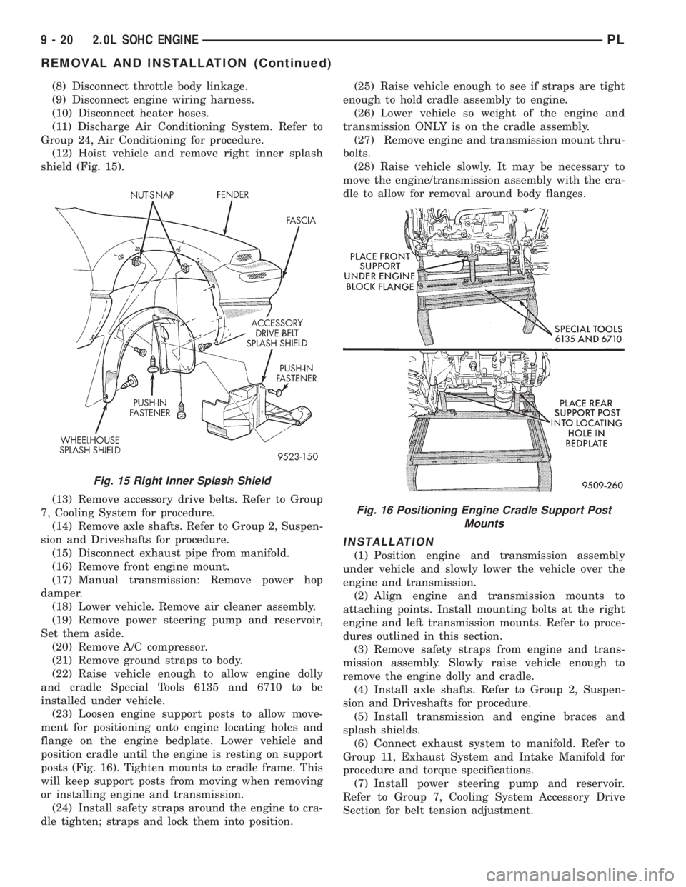
(12) Hoist vehicle and remove right inner splash
shield (Fig. 15).
(13) Remove accessory drive belts. Refer to Group
7, Cooling System for procedure.
(14) Remove axle shafts. Refer to Group 2, Suspen-
sion and Driveshafts for procedure.
(15) Disconnect exhaust pipe from manifold.
(16) Remove front engine mount.
(17) Manual transmission: Remove power hop
damper.
(18) Lower vehicle. Remove air cleaner assembly.
(19) Remove power steering pump and reservoir,
Set them aside.
(20) Remove A/C compressor.
(21) Remove ground straps to body.
(22) Raise vehicle enough to allow engine dolly
and cradle Special Tools 6135 and 6710 to be
installed under vehicle.
(23) Loosen engine support posts to allow move-
ment for positioning onto engine locating holes and
flange on the engine bedplate. Lower vehicle and
position cradle until the engine is resting on support
posts (Fig. 16). Tighten mounts to cradle frame. This
will keep support posts from moving when removing
or installing engine and transmission.
(24) Install safety straps around the engine to cra-
dle tighten; straps and lock them into position.(25) Raise vehicle enough to see if straps are tight
enough to hold cradle assembly to engine.
(26) Lower vehicle so weight of the engine and
transmission ONLY is on the cradle assembly.
(27) Remove engine and transmission mount thru-
bolts.
(28) Raise vehicle slowly. It may be necessary to
move the engine/transmission assembly with the cra-
dle to allow for removal around body flanges.
INSTALLATION
(1) Position engine and transmission assembly
under vehicle and slowly lower the vehicle over the
engine and transmission.
(2) Align engine and transmission mounts to
attaching points. Install mounting bolts at the right
engine and left transmission mounts. Refer to proce-
dures outlined in this section.
(3) Remove safety straps from engine and trans-
mission assembly. Slowly raise vehicle enough to
remove the engine dolly and cradle.
(4) Install axle shafts. Refer to Group 2, Suspen-
sion and Driveshafts for procedure.
(5) Install transmission and engine braces and
splash shields.
(6) Connect exhaust system to manifold. Refer to
Group 11, Exhaust System and Intake Manifold for
procedure and torque specifications.
(7) Install power steering pump and reservoir.
Refer to Group 7, Cooling System Accessory Drive
Section for belt tension adjustment.
Fig. 15 Right Inner Splash Shield
Fig. 16 Positioning Engine Cradle Support Post
Mounts
9 - 20 2.0L SOHC ENGINEPL
REMOVAL AND INSTALLATION (Continued)
Page 734 of 1200
(8) Install A/C compressor and hoses. Refer to
Group 24, Heater and Air Conditioning for procedure.
(9) Install accessory drive belts. Refer to Group 7,
Cooling System Accessory Drive Section for belt ten-
sion adjustment.
(10) Install front engine mount. Refer to this sec-
tion for procedure.
(11) Manual transmission: Install power hop
damper.
(12) Install inner splash shield. Install wheels and
tires.
(13)Manual Transmission:Connect clutch cable
and linkages. Refer to Group 6, Manual Transaxle
Clutch.
(14)Automatic Transmission:Connect shifter
and kickdown linkage. Refer to Group 21, Transaxle
for procedures.
(15) Connect fuel line and heater hoses.
(16) Install ground straps. Connect engine and
throttle body connections and harnesses. Refer to
Group 8, Electrical for procedure.
(17) Connect throttle body linkage. Refer to Group
14, Fuel System for procedure.
(18) Install radiator and shroud assembly. Install
radiator hoses. Fill cooling system. Refer to Group 7,
Cooling System for filling procedure.
(19) Install battery tray and battery. Set Power-
train Control Module (PCM) into place.
(20) Install air cleaner and hoses.
(21) Install oil filter. Fill engine crankcase with
proper oil to correct level.
(22) Perform camshaft and crankshaft timing
relearn procedure as follows:
²Connect the DRB scan tool to the data link
(diagnostic) connector. This connector is located in
the passenger compartment; at the lower edge of
instrument panel; near the steering column.
²Turn the ignition switch on and access the ªmis-
cellaneousº screen.
²Select ªre-learn cam/crankº option and follow
directions on DRB screen.
(23) Start engine and run until operating temper-
ature is reached.
(24) Adjust transmission linkage, if necessary.
CYLINDER HEAD COVER
REMOVAL
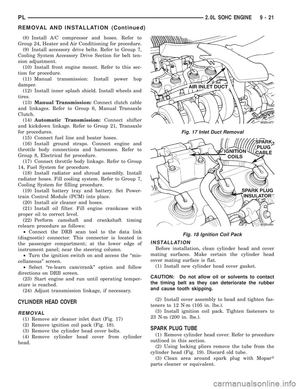
(1) Remove air cleaner inlet duct (Fig. 17)
(2) Remove ignition coil pack (Fig. 18).
(3) Remove the cylinder head cover bolts.
(4) Remove cylinder head cover from cylinder
head.
INSTALLATION
Before installation, clean cylinder head and cover
mating surfaces. Make certain the cylinder head
cover mating surface is flat.
(1) Install new cylinder head cover gasket.
CAUTION: Do not allow oil or solvents to contact
the timing belt as they can deteriorate the rubber
and cause tooth skipping.
(2) Install cover assembly to head and tighten fas-
teners to 12 N´m (105 in. lbs.).
(3) Install ignition coil pack. Tighten fasteners to
23 N´m (200 in. lbs.).
SPARK PLUG TUBE
(1) Remove cylinder head cover. Refer to procedure
outlined in this section.
(2) Using locking pliers remove the tube from the
cylinder head (Fig. 19). Discard old tube.
(3) Clean area around spark plug with Mopart
parts cleaner or equivalent.
Fig. 17 Inlet Duct Removal
Fig. 18 Ignition Coil Pack
PL2.0L SOHC ENGINE 9 - 21
REMOVAL AND INSTALLATION (Continued)
Page 778 of 1200
²Step 1: Install the collar to oil pan bolts and
tighten to 3 N´m (30 in. lbs.).
²Step 2: Install collar to transaxle bolts and
tighten to 108 N´m (80 ft. lbs.).
²Step 3: Final torque the collar to oil pan bolts to
54 N´m (40 ft. lbs.).
(2) Lower vehicle.
ENGINE ASSEMBLY
REMOVAL
(1) Perform fuel pressure release procedure. Refer
to Group 14, Fuel System for procedure. Remove fuel
line to fuel rail.
(2) Disconnect and remove battery and tray. Set
Powertrain Control Module (PCM) aside.
(3) Drain cooling system. Refer to Group 7, Cooling
System for procedure.
(4) Remove upper radiator hose, radiator and fan
module. Refer to Group 7, Cooling System for proce-
dure.
(5) Remove lower radiator hose.
(6) Disconnect automatic transmission cooler lines
and plug. If equipped.
(7) Disconnect clutch cable (Manual) and transmis-
sion shift linkage.
(8) Disconnect throttle body linkage.
(9) Disconnect engine wiring harness.
(10) Disconnect heater hoses.
(11) Discharge Air Conditioning System. Refer to
Group 24, Air Conditioning for procedure.
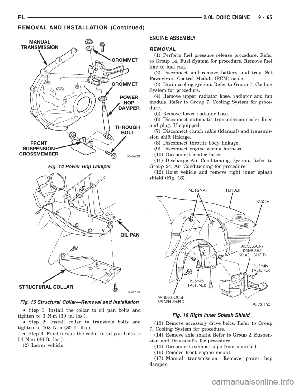
(12) Hoist vehicle and remove right inner splash
shield (Fig. 16).
(13) Remove accessory drive belts. Refer to Group
7, Cooling System for procedure.
(14) Remove axle shafts. Refer to Group 2, Suspen-
sion and Driveshafts for procedure.
(15) Disconnect exhaust pipe from manifold.
(16) Remove front engine mount.
(17) Manual transmission: Remove power hop
damper.
Fig. 14 Power Hop Damper
Fig. 15 Structural CollarÐRemoval and Installation
Fig. 16 Right Inner Splash Shield
PL2.0L DOHC ENGINE 9 - 65
REMOVAL AND INSTALLATION (Continued)
Page 779 of 1200
(18) Lower vehicle. Remove air cleaner assembly.
(19) Remove power steering pump and reservoir,
Set them aside.
(20) Remove A/C compressor.
(21) Remove ground straps to body.
(22) Raise vehicle enough to allow engine dolly
and cradle Special Tools 6135 and 6710 to be
installed under vehicle.
(23) Loosen engine support posts to allow move-
ment for positioning onto engine locating holes and
flange on the engine bedplate. Lower vehicle and
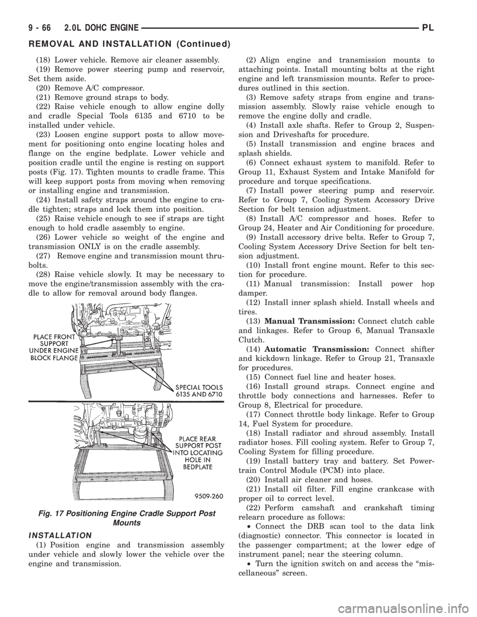
position cradle until the engine is resting on support
posts (Fig. 17). Tighten mounts to cradle frame. This
will keep support posts from moving when removing
or installing engine and transmission.
(24) Install safety straps around the engine to cra-
dle tighten; straps and lock them into position.
(25) Raise vehicle enough to see if straps are tight
enough to hold cradle assembly to engine.
(26) Lower vehicle so weight of the engine and
transmission ONLY is on the cradle assembly.
(27) Remove engine and transmission mount thru-
bolts.
(28) Raise vehicle slowly. It may be necessary to
move the engine/transmission assembly with the cra-
dle to allow for removal around body flanges.
INSTALLATION
(1) Position engine and transmission assembly
under vehicle and slowly lower the vehicle over the
engine and transmission.(2) Align engine and transmission mounts to
attaching points. Install mounting bolts at the right
engine and left transmission mounts. Refer to proce-
dures outlined in this section.
(3) Remove safety straps from engine and trans-
mission assembly. Slowly raise vehicle enough to
remove the engine dolly and cradle.
(4) Install axle shafts. Refer to Group 2, Suspen-
sion and Driveshafts for procedure.
(5) Install transmission and engine braces and
splash shields.
(6) Connect exhaust system to manifold. Refer to
Group 11, Exhaust System and Intake Manifold for
procedure and torque specifications.
(7) Install power steering pump and reservoir.
Refer to Group 7, Cooling System Accessory Drive
Section for belt tension adjustment.
(8) Install A/C compressor and hoses. Refer to
Group 24, Heater and Air Conditioning for procedure.
(9) Install accessory drive belts. Refer to Group 7,
Cooling System Accessory Drive Section for belt ten-
sion adjustment.
(10) Install front engine mount. Refer to this sec-
tion for procedure.
(11) Manual transmission: Install power hop
damper.
(12) Install inner splash shield. Install wheels and
tires.
(13)Manual Transmission:Connect clutch cable
and linkages. Refer to Group 6, Manual Transaxle
Clutch.
(14)Automatic Transmission:Connect shifter
and kickdown linkage. Refer to Group 21, Transaxle
for procedures.
(15) Connect fuel line and heater hoses.
(16) Install ground straps. Connect engine and
throttle body connections and harnesses. Refer to
Group 8, Electrical for procedure.
(17) Connect throttle body linkage. Refer to Group
14, Fuel System for procedure.
(18) Install radiator and shroud assembly. Install
radiator hoses. Fill cooling system. Refer to Group 7,
Cooling System for filling procedure.
(19) Install battery tray and battery. Set Power-
train Control Module (PCM) into place.
(20) Install air cleaner and hoses.
(21) Install oil filter. Fill engine crankcase with
proper oil to correct level.
(22) Perform camshaft and crankshaft timing
relearn procedure as follows:
²Connect the DRB scan tool to the data link
(diagnostic) connector. This connector is located in
the passenger compartment; at the lower edge of
instrument panel; near the steering column.
²Turn the ignition switch on and access the ªmis-
cellaneousº screen.
Fig. 17 Positioning Engine Cradle Support Post
Mounts
9 - 66 2.0L DOHC ENGINEPL
REMOVAL AND INSTALLATION (Continued)
Page 824 of 1200

INTAKE MANIFOLDÐDOHC ENGINE
REMOVAL
WARNING: RELEASE FUEL SYSTEM PRESSURE
BEFORE SERVICING FUEL SYSTEM COMPONENTS.
SERVICE VEHICLES IN WELL VENTILATED AREAS
AND AVOID IGNITION SOURCES. NEVER SMOKE
WHILE SERVICING THE VEHICLE.
(1) Disconnect negative cable from battery.
(2) Remove fuel filler cap.
(3) Loosen wing nut on intake and remove fresh
air inlet duct (Fig. 23).
(4) Remove the protective cap from the fuel pres-
sure test port on the fuel rail (Fig. 21).
(5) Place the open end of fuel pressure release
hose, Special Tool C-4799-1, into an approved gaso-
line container. Connect the other end of hose to the
fuel pressure test port (Fig. 22). Fuel pressure will
bleed off through the hose into the gasoline con-
tainer. Fuel gauge C-4799-A contains hose C-4799-1.
(6) Disconnect the fuel supply line quick-connect at
the fuel tube assembly.
(7) Remove clean air inlet duct.WARNING: WRAP SHOP TOWELS AROUND HOSE
TO CATCH ANY GASOLINE SPILLAGE.
(8) Disconnect the coolant temperature sensor
(Fig. 24).
(9) Disconnect heater hose from intake manifold.
(10) Disconnect heater tube from bottom of intake
manifold.
(11) Disconnect upper radiator hose and coolant
recovery hose.
(12) Remove fuel rail assembly attaching screws
and remove fuel rail assembly from engine. Cover
injector holes with suitable covering.
CAUTION: Do not set fuel injectors on their tips,
damage may occur to the injectors
Fig. 21 Fuel Pressure Test PortÐTypical
Fig. 22 Releasing Fuel PressureÐTypical
Fig. 23 Fresh Air Inlet Duct
Fig. 24 Engine Coolant Temperature Sensor
PLEXHAUST SYSTEM AND INTAKE MANIFOLD 11 - 9
REMOVAL AND INSTALLATION (Continued)
Page 825 of 1200
(13) Remove accelerator, kickdown and speed con-
trol cables from throttle lever and bracket. Refer to
Group 14, Fuel System Throttle Body Removal for
procedures.
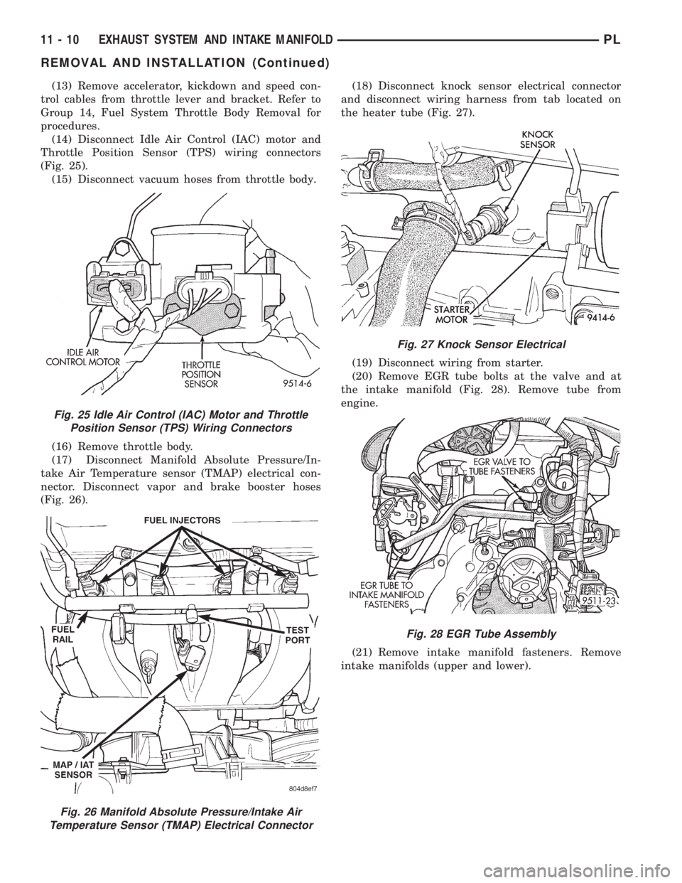
(14) Disconnect Idle Air Control (IAC) motor and
Throttle Position Sensor (TPS) wiring connectors
(Fig. 25).
(15) Disconnect vacuum hoses from throttle body.
(16) Remove throttle body.
(17) Disconnect Manifold Absolute Pressure/In-
take Air Temperature sensor (TMAP) electrical con-
nector. Disconnect vapor and brake booster hoses
(Fig. 26).(18) Disconnect knock sensor electrical connector
and disconnect wiring harness from tab located on
the heater tube (Fig. 27).
(19) Disconnect wiring from starter.
(20) Remove EGR tube bolts at the valve and at
the intake manifold (Fig. 28). Remove tube from
engine.
(21) Remove intake manifold fasteners. Remove
intake manifolds (upper and lower).
Fig. 25 Idle Air Control (IAC) Motor and Throttle
Position Sensor (TPS) Wiring Connectors
Fig. 26 Manifold Absolute Pressure/Intake Air
Temperature Sensor (TMAP) Electrical Connector
Fig. 27 Knock Sensor Electrical
Fig. 28 EGR Tube Assembly
11 - 10 EXHAUST SYSTEM AND INTAKE MANIFOLDPL
REMOVAL AND INSTALLATION (Continued)
Page 826 of 1200

INSTALLATION
Before installing manifolds. Clean all mating sur-
faces. Replace all gaskets, with new.
(1) Assemble lower manifold to upper (if sepa-
rated) and tighten bolts in sequence shown in (Fig.
29) to 28 N´m (250 in. lbs.).
(2) Install intake manifold onto cylinder head and
tighten fasteners to 28 N´m (250 in. lbs.) in sequence
shown in (Fig. 30).
(3) Remove covering from fuel injector holes and
insure the holes are clean. Install fuel rail assembly
to intake manifold. Tighten screws to 23 N´m (200 in.
lbs.).
(4) Connect PCV and brake booster hoses.
(5) Inspect quick connect fittings for damage,
replace if necessary Refer to Group 14, Fuel System
for procedure. Apply a light amount of clean engine
oil to fuel inlet tube. Connect fuel supply hose to fuel
rail assembly. Check connection by pulling on connec-
tor to insure it locked into position.
(6) Connect heater tube and hose to intake mani-
fold.
(7) Connect upper radiator hose and coolant recov-
ery hose.
(8) Connect coolant temperature sensor wiring con-
nector.
(9) Install throttle body. Tighten fastener to 22
N´m (200 in. lbs.).
(10) Connect Manifold Absolute Pressure/Intake
Air Temperature Sensor (TMAP) wiring connector.(11) Connect knock sensor connector and starter
wires. Connect wiring harness to heater tube tab.
(12) Connect Idle Air Control (IAC) motor and
Throttle Position Sensor (TPS) wiring connectors.
(13) Connect vacuum hoses to throttle body.
(14) Install accelerator, kickdown and speed con-
trol cables to their bracket and connect them to the
throttle lever. Refer to Group 14, Fuel System Throt-
tle Body Installation for procedure.
(15) Loose assemble the EGR tube onto valve and
intake manifold finger tight. Tighten tube fasteners
at the EGR valve first to 11 N´m (95 in. lbs.) then,
tighten the intake manifold side fasteners to 11 N´m
(95 in. lbs.).
(16) Install fresh air duct to air filter housing.
Tighten clamp to 3 N´m (25 in. lbs.).
(17) Connect negative cable to battery.
(18) With the DRB scan tool use ASD Fuel System
Test to pressurize system to check for leaks.
CAUTION: When using the ASD Fuel System Test,
the Auto Shutdown (ASD) relay will remain ener-
gized for 7 minutes or until the ignition switch is
turned to the OFF position, or Stop All Test is
selected.
EXHAUST MANIFOLD
REMOVAL
(1) Remove air cleaner assembly and bracket.
(2) Remove exhaust manifold heat shield (Fig. 31).
(3) Disconnect upstream heated oxygen sensor con-
nector.
Fig. 29 Lower Intake Manifold to Upper Tightening
Sequence
Fig. 30 Intake Manifold To Cylinder Head Tightening
Sequence
Fig. 31 Exhaust Manifold Heat Shield
PLEXHAUST SYSTEM AND INTAKE MANIFOLD 11 - 11
REMOVAL AND INSTALLATION (Continued)
Page 864 of 1200

below the minimum acceptable percentage, the PCM
stores a diagnostic trouble code in memory.
During certain idle conditions, the PCM may enter
a variable idle speed strategy. During variable idle
speed strategy the PCM adjusts engine speed based
on the following inputs.
²A/C sense
²Battery voltage
²Battery temperature
²Engine coolant temperature
²Engine run time
²Power steering pressure switch
²Vehicle mileage
ACCELERATION MODE
This is a CLOSED LOOP mode. The PCM recog-
nizes an abrupt increase in Throttle Position sensor
output voltage or MAP sensor output voltage as a
demand for increased engine output and vehicle
acceleration. The PCM increases injector pulse width
in response to increased fuel demand.
DECELERATION MODE
This is a CLOSED LOOP mode. During decelera-
tion the following inputs are received by the PCM:
²A/C pressure transducer
²A/C sense
²Battery voltage
²Intake air temperature
²Engine coolant temperature
²Crankshaft position (engine speed)
²Exhaust gas oxygen content (upstream heated
oxygen sensor)
²Knock sensor
²Manifold absolute pressure
²Power steering pressure switch
²Throttle position
²IAC motor control changes in respones to MAP
sensor feedback
The PCM may receive a closed throttle input from
the Throttle Position Sensor (TPS) when it senses an
abrupt decrease in manifold pressure. This indicates
a hard deceleration. In response, the PCM may
momentarily turn off the injectors. This helps
improve fuel economy, emissions and engine braking.
If decel fuel shutoff is detected, downstream oxy-
gen sensor diagnostics is performed.
WIDE-OPEN-THROTTLE MODE
This is an OPEN LOOP mode. During wide-open-
throttle operation, the following inputs are received
by the PCM:
²Intake air temperature
²Engine coolant temperature
²Engine speed
²Knock sensor
²Manifold absolute pressure²Throttle position
When the PCM senses a wide-open-throttle condi-
tion through the Throttle Position Sensor (TPS) it de-
energizes the A/C compressor clutch relay. This
disables the air conditioning system.
The PCM does not monitor the heated oxygen sen-
sor inputs during wide-open-throttle operation except
for downstream heated oxygen sensor and both
shorted diagnostics. The PCM adjusts injector pulse
width to supply a predetermined amount of addi-
tional fuel.
IGNITION SWITCH OFF MODE
When the operator turns the ignition switch to the
OFF position, the following occurs:
²All outputs are turned off, unless 02 Heater
Monitor test is being run. Refer to Group 25,
On-Board Diagnostics.
²No inputs are monitored except for the heated
oxygen sensors. The PCM monitors the heating ele-
ments in the oxygen sensors and then shuts down.
DESCRIPTION AND OPERATION
SYSTEM DIAGNOSIS
The PCM can test many of its own input and out-
put circuits. If the PCM senses a fault in a major
system, the PCM stores a Diagnostic Trouble Code
(DTC) in memory.
For DTC information, refer to Group 25, Emission
Control Systems. See On-Board Diagnostics.
POWER DISTRIBUTION CENTER
The power distribution center (PDC) is located next
to the battery (Fig. 1). The PDC contains the starter
relay, radiator fan relay, A/C compressor clutch relay,
auto shutdown relay, fuel pump relay and several
fuses.
Fig. 1 Power Distribution Center (PDC)
PLFUEL SYSTEM 14 - 23
GENERAL INFORMATION (Continued)