Page 1882 of 3115
EM0EE-18
A19478
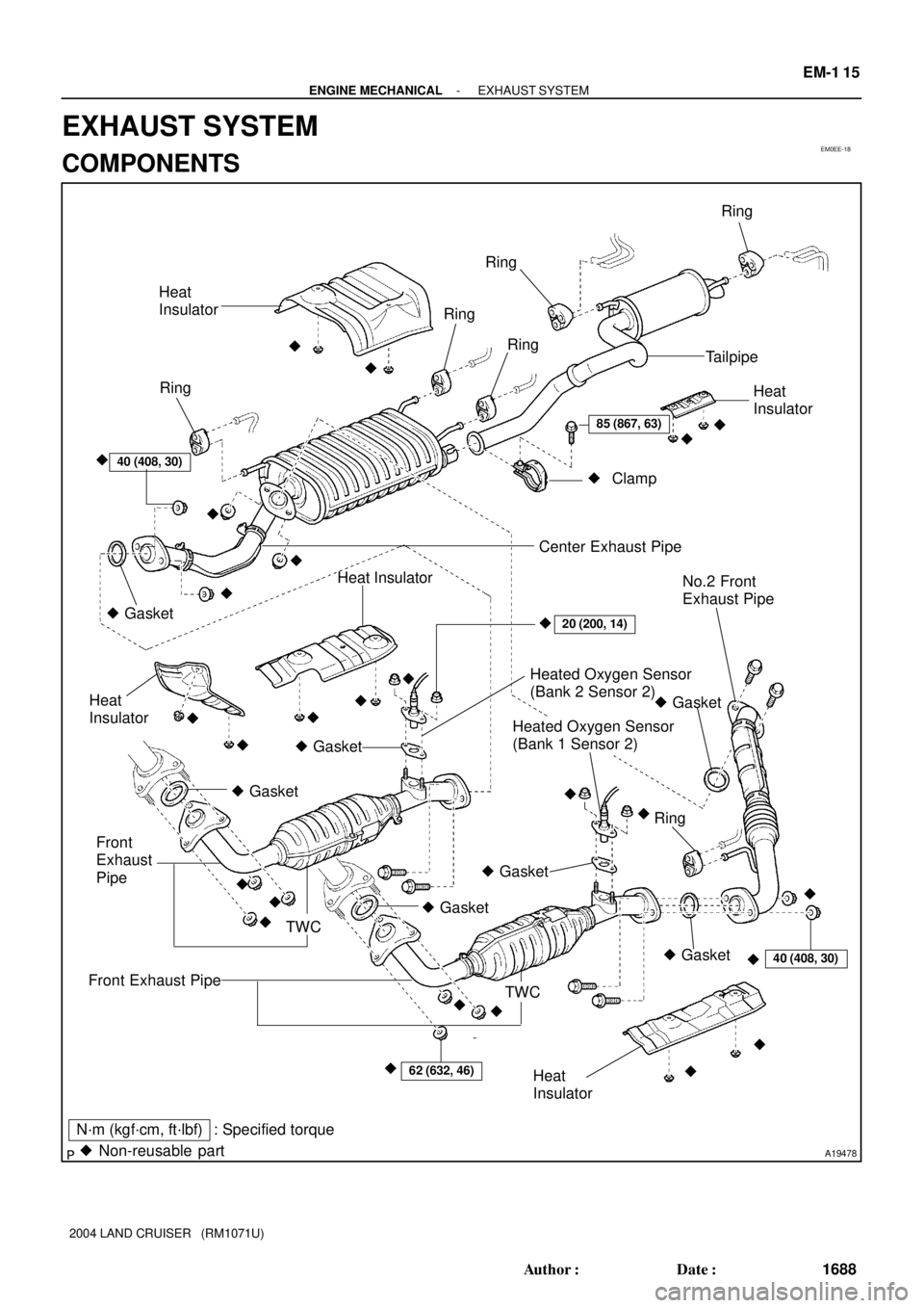
N´m (kgf´cm, ft´lbf) : Specified torque
� Non-reusable partHeat
Insulator
Ring
Heat
Insulator
� Gasket Center Exhaust PipeRing
� Gasket
Heat
Insulator
40 (408, 30)
40 (408, 30)
Heated Oxygen Sensor
(Bank 2 Sensor 2)
�
��
��
�Ring
�
�
Heated Oxygen Sensor
(Bank 1 Sensor 2)��Clamp
Ring
Ring
��
20 (200, 14)
� Gasket
� Gasket
No.2 Front
Exhaust Pipe
Ring
�� Heat Insulator
Tailpipe
� Gasket
� Gasket
Heat
Insulator62 (632, 46)
TWC Front Exhaust Pipe
Front
Exhaust
Pipe
TWC
� Gasket
� �
�
� �
�
� ��� �
��
�
85 (867, 63)
- ENGINE MECHANICALEXHAUST SYSTEM
EM-1 15
1688 Author�: Date�:
2004 LAND CRUISER (RM1071U)
EXHAUST SYSTEM
COMPONENTS
Page 1887 of 3115
A04326
RH No. 3 Timing Belt Cover
No. 2 Timing
Belt Cover
LH No. 3 Timing Belt Cover Drive Belt Idler Pulley
Camshaft Position
Sensor ConnectorCover Plate
Engine Wire
16 (160, 12)
7.5 (80, 16 in.´lbf)
N´m (kgf´cm, ft´lbf) : Specified torque
Oil Cooler PipeWire Grommet
39 (400, 29)
7.5 (80, 66 in.´lbf)
A04327
Timing BeltRH Camshaft Timing Pulley
LH Camshaft Timing Belt Pulley
Timing belt Tensioner
Fan BracketDust Boot
108 (1,100, 80)
245 (2,500, 181)
16 (160, 12)
32 (330, 24)
26 (270, 19)N´m (kgf´cm, ft´lbf) : Specified torque
- ENGINE MECHANICALTIMING BELT
EM-13
1586 Author�: Date�:
2004 LAND CRUISER (RM1071U)
Page 1888 of 3115
A19486
Generator Wire
Drive Belt Tensioner
No.1 Timing Belt Cover
Generator
Crankshaft Pulley
No.1 Idler Pulley
Timing Belt
Plate Washer
Crankshaft Timing Pulley
Timing Belt Cover Spacer No.2 Idler Pulley Timing Belt Guide
(Crankshaft Angle Sensor Plate)
Gasket
34.5 (350, 25)
�
N´m (kgf´cm, ft´lbf) : Specified torque
� Precoated part
34.5 (350, 25)
39 (400, 29)
39 (400, 29)
15.5 (158, 11)
EM-14
- ENGINE MECHANICALTIMING BELT
1587 Author�: Date�:
2004 LAND CRUISER (RM1071U)
Page 1895 of 3115

20. INSTALL NO.2 TIMING BELT COVER
Install the No.2 timing belt cover with the 2 bolts.
Tor")
A04330
A04329
A04331
EM-26
- ENGINE MECHANICALTIMING BELT
1599 Author�: Date�:
2004 LAND CRUISER (RM1071U)
20. INSTALL NO.2 TIMING BELT COVER
Install the No.2 timing belt cover with the 2 bolts.
Torque: 16 N´m (160 kgf´cm, 12 ft´lbf)
21. INSTALL RH NO.3 TIMING BELT COVER
(a) Fit the RH No.3 timing belt cover, matching it with the fan
bracket.
(b) Install the RH No.3 timing belt cover with the 3 bolts and
nut.
Torque: 7.5 N´m (80 kgf´cm, 66 in.´lbf)
22. INSTALL LH NO.3 TIMING BELT COVER
(a) Install the oil cooler pipe and the bolt.
(b) Run the camshaft position sensor wire through the LH
No.3 timing belt cover hole.
(c) Fit the LH No.3 timing belt cover, matching it with the fan
bracket.
(d) Install the LH No.3 timing belt cover with the 4 bolts and
the nut.
Torque: 7.5 N´m (80 kgf´cm, 66 in.´lbf)
(e) Install the wire grommet to the LH No.3 timing belt cover.
(f) Install the sensor connector to the connector bracket.
(g) Connect the sensor connector.
(h) Install the sensor wire to the wire clamp on the LH No.3
timing belt cover.
(i) Install the engine wire to the 2 wire clamps on the LH No.3
timing belt cover.
23. INSTALL DRIVE BELT IDLER PULLEY
Install the idler pulley and the cover plate with the bolt.
Torque: 37 N´m (380 kgf´cm, 27 ft´lbf)
24. INSTALL RADIATOR ASSEMBLY
(See page CO-19)
Page 1898 of 3115

11. REMOVE LH NO.3 TIMING BELT COVER
(a) Disconnect the engine wire from the 2 wire")
A04331
A04330
A04455
A04332
EM-16
- ENGINE MECHANICALTIMING BELT
1589 Author�: Date�:
2004 LAND CRUISER (RM1071U)
11. REMOVE LH NO.3 TIMING BELT COVER
(a) Disconnect the engine wire from the 2 wire clamps.
(b) Remove the 4 bolts and the nut.
(c) Disconnect the camshaft position sensor wire from the
wire clamp on the LH No.3 timing belt cover.
(d) Disconnect the sensor connector from the connector
bracket.
(e) Disconnect the camshaft position sensor connector.
(f) Remove the wire grommet from the LH No.3 timing belt
cover.
(g) Remove the LH No.3 timing belt cover.
(h) Remove the oil cooler pipe and the 2 bolts.
12. REMOVE NO.2 TIMING BELT COVER
Remove the 2 bolts and the No.2 timing belt cover.
13. DISCONNECT A/C COMPRESSOR FROM ENGINE
(See page EM-77)
14. REMOVE FAN BRACKET
Remove the 2 bolts, the 2 nuts and the fan bracket.
15. IF RE-USING TIMING BELT, CHECK
INSTALLATION MARKS ON TIMING BELT
Check that there are 3 installation marks on the timing belt as
turning the crankshaft pulley as shown in the illustration.
HINT:
If the installation marks are disappeared, place a new installa-
tion mark on the timing belt before removing each part.
Page 1911 of 3115
[A]
[B]
[H] [D]
[F] [E]
[ I ]
[L]
[M][J]
[K][G] [C]
1 2
IBIB
34
4 7
2111134
1 2
6 3
1 2
B18
BLRL
GR
B18 GR
3 4
Rear Combination Light RH R 7
Rear Combination Light LH R 6
High Mounted
Stop Light H17Light Failure Sensor Stop Light SW
ABS ECUS 6
Combination
Meter C 7
BV11
WB(Shielded) BV11I 5 GWIB 2IB 1
IE1 14
BO
50
8L 4 15A
STOP7.5A
GAUGE From Power Source System (See Page 66)
Stop Light
GR WB WB
WB
WBGB
YG RLR GR
WR GW WB
GW
W/ G)
(
S/D)
L L(
(
S/D)
Stop
Stop
Rear
Lights
2004 LAND CRUISER (EWD548U)
4B HOW TO USE THIS MANUAL
*The system shown here is an EXAMPLE ONLY. It is different to the actual
circuit shown in the SYSTEM CIRCUITS SECTION.
Page 1913 of 3115
![TOYOTA LAND CRUISER 1998 Factory Repair Manual [N]
[O]
[P]
[Q]
[R]
[S]
[T]
[U]
2004 LAND CRUISER (EWD548U)
6B HOW TO USE THIS MANUAL
Current is applied at all times through the STOP fuse to TERMINAL 2 of the stop light SW.
When the ignition SW is](/manual-img/14/57459/w960_57459-1912.png "TOYOTA LAND CRUISER 1998 Factory Repair Manual [N]
[O]
[P]
[Q]
[R]
[S]
[T]
[U]
2004 LAND CRUISER (EWD548U)
6B HOW TO USE THIS MANUAL
Current is applied at all times through the STOP fuse to TERMINAL 2 of the stop light SW.
When the ignition SW is")
[N]
[O]
[P]
[Q]
[R]
[S]
[T]
[U]
2004 LAND CRUISER (EWD548U)
6B HOW TO USE THIS MANUAL
Current is applied at all times through the STOP fuse to TERMINAL 2 of the stop light SW.
When the ignition SW is turned on, current flows from the GAUGE fuse to TERMINAL 8 of the light failure sensor, and also flows
through the rear lights warning light to TERMINAL 4 of the light failure sensor.
Stop Light Disconnection Warning
When the ignition SW is turned on and the brake pedal is pressed (Stop light SW on), if the stop light circuit is open, the current
flowing from TERMINAL 7 of the light failure sensor to TERMINALS 1, 2 changes, so the light failure sensor detects the
disconnection and the warning circuit of the light failure sensor is activated.
As a result, the current flows from TERMINAL 4 of the light failure sensor to TERMINAL 11 to GROUND and turns the rear lights
warning light on. By pressing the brake pedal, the current flowing to TERMINAL 8 of the light failure sensor keeps the warning
circuit on and holds the warning light on until the ignition SW is turned off.
S6 Stop Light SW
2-1 : Closed with the brake pedal depressed
L4 Light Failure Sensor
1, 2, 7-Ground : Approx. 12 volts with the stop light SW on
4, 8-Ground : Approx. 12 volts with the ignition SW at ON position
11-Ground : Always continuity
: Parts Location
CodeSee PageCodeSee PageCodeSee Page
C734L436R737
H1736R637S635
: Relay Blocks
CodeSee PageRelay Blocks (Relay Block Location)
118R/B No.1 (Instrument Panel Brace LH)
: Junction Block and Wire Harness Connector
CodeSee PageJunction Block and Wire Harness (Connector Location)
IB20Instrument Panel Wire and Instrument Panel J/B (Lower Finish Panel)
3C22Instrument Panel Wire and J/B No.3 (Instrument Panel Brace LH)
: Connector Joining Wire Harness and Wire Harness
CodeSee PageJoining Wire Harness and Wire Harness (Connector Location)
IE142Floor Wire and Instrument Panel Wire (Left Kick Panel)
BV150Luggage Room Wire and Floor Wire (Luggage Room Left)
: Ground Points
CodeSee PageGround Points Location
BL50Under the Left Center Pillar
BO50Back Panel Center
: Splice Points
CodeSee PageWire Harness with Splice PointsCodeSee PageWire Harness with Splice Points
I544Cowl WireB1850Luggage Room Wire
System Outline
Service Hints
Page 1914 of 3115
![TOYOTA LAND CRUISER 1998 Factory Repair Manual 2004 LAND CRUISER (EWD548U)
7 B
[N]: Explains the system outline.
[O]: Indicates values or explains the function for reference during troubleshooting.
[P]: Indicates the reference page showing the pos](/manual-img/14/57459/w960_57459-1913.png "TOYOTA LAND CRUISER 1998 Factory Repair Manual 2004 LAND CRUISER (EWD548U)
7 B
[N]: Explains the system outline.
[O]: Indicates values or explains the function for reference during troubleshooting.
[P]: Indicates the reference page showing the pos")
2004 LAND CRUISER (EWD548U)
7 B
[N]: Explains the system outline.
[O]: Indicates values or explains the function for reference during troubleshooting.
[P]: Indicates the reference page showing the position on the vehicle of the parts in the system circuit.
Example : Part ºL4º (Light Failure Sensor) is on page 36 of the manual.
*The letter in the code is from the first letter of the part, and the number indicates its order in parts
starting with that letter.
Example : L 4� �Parts is 4th in order
Light Failure Sensor
[Q]: Indicates the reference page showing the position on the vehicle of Relay Block Connectors in the system circuit.
Example : Connector º1º is described on page 18 of this manual and is installed on the left side of the instrument
panel.
[R]: Indicates the reference page showing the position on the vehicle of J/B and Wire Harness in the system circuit.
Example : Connector º3Cº connects the Instrument Panel Wire and J/B No.3. It is described on page 22 of this
manual, and is installed on the instrument panel left side.
[S]: Indicates the reference page describing the wiring harness and wiring harness connector (the female wiring
harness is shown first, followed by the male wiring harness).
Example : Connector ºIE1º connects the floor wire (female) and Instrument panel wire (male). It is described on
page 42 of this manual, and is installed on the left side kick panel.
[T]: Indicates the reference page showing the position of the ground points on the vehicle.
Example : Ground point ºBOº is described on page 50 of this manual and is installed on the back panel center.
[U]: Indicates the reference page showing the position of the splice points on the vehicle.
Example : Splice point ºI5º is on the Cowl Wire Harness and is described on page 44 of this manual.

7.5 (80, 16 in.´lbf")

![TOYOTA LAND CRUISER 1998 Factory Repair Manual
[A]
[B]
[H] [D]
[F] [E]
[ I ]
[L]
[M][J]
[K][G] [C]
1 2
IBIB
34
4 7
2111134
1 2
6 3
1 2
B18
BLRL
GR
B18 GR
3 4
Rear Combination Light RH R 7
Rear Combination Light LH R 6
High Mounted
Stop Light H1](/manual-img/14/57459/w960_57459-1910.png "TOYOTA LAND CRUISER 1998 Factory Repair Manual
[A]
[B]
[H] [D]
[F] [E]
[ I ]
[L]
[M][J]
[K][G] [C]
1 2
IBIB
34
4 7
2111134
1 2
6 3
1 2
B18
BLRL
GR
B18 GR
3 4
Rear Combination Light RH R 7
Rear Combination Light LH R 6
High Mounted
Stop Light H1")