Page 1761 of 3115

(c) Prepare the hand-held tester.
(d) Connect the hand-held to DLC3.
(e) Tur")
I24672
Hand-held tester
DLC3
DI-962
- DIAGNOSTICSTHEFT DETERRENT SYSTEM
1155 Author�: Date�:
2004 LAND CRUISER (RM1071U)
(c) Prepare the hand-held tester.
(d) Connect the hand-held to DLC3.
(e) Turn the ignition switch ON and the hand-held tester
main switch ON.
(f) Use the hand-held tester to check the DTCs, note them
down. (For opening instructions, see the hand-held tes-
ter 's intrusion book).
10. DATA LIST
HINT:
By the DATA LIST displayed on the Hand-held tester, you can read the value of the switch, sensor, actuator
and so on without removing any parts. Reading the DATA LIST as a first step of troubleshooting is one of
the method to shorten the labor time.
(a) Turn the ignition switch OFF.
(b) Connect the hand-held tester to DLC3.
(c) Turn the ignition switch ON.
(d) According to the display on the tester, read the ºDATA LISTº.
THEFT DETERRENT ECU:
ItemConditionSpecified Condition
HOOD COURTSY SWEngine hood Close " OpenOFF/ON
INTRS DETECTIntrusion sensor detection OFF " ONOFF/ON
GLS BRK DETECTGlass broken sensor detection OFF " ONOFF/ON
KEY UNLK WRN SWInsert keyOFF/ON
IG SWIG switch ON or otherOFF/ON
PASSIVE MODEPassive mode " other modeOFF/ON
WARN BY GLS SENWarning by glass broken sensor OFF " ONOFF/ON
INTRUSION SENIntrusion sensor OFF " ONOFF/ON
WARNING (HORN)Warning by Horn OFF " ONOFF/ON
ENTRY DELAYEntry delay time0 s/14 s /30 s
11. ACTIVE TEST
HINT:
Performing ACTIVE TEST using the Hand-held tester allows the relay, and so on to operate without remov-
ing any parts. Performing ACTIVE TEST as a first step of troubleshooting is one of the method to shorten
the labor time.
DATA LIST can be displayed during ACTIVE TEST.
(a) Turn the ignition switch OFF.
(b) Connect the Hand-held tester to DLC3.
(c) Turn the ignition switch ON.
(d) According to the display on tester, perform the ºACTIVE TESTº.
THEFT DETERRENT ECU:
ItemTest detailsDiagnostic note
SECURITY INDICTurns security indicator ON/OFFConnect terminals TC and E1 of DLC1
SECURITY HORN2Turns security horn2 ON/OFF-
Page 1763 of 3115

DI1AH-21
40 39 38 37 36 35 34 33 32 31 30 29 28 27 26 25 24 23 22 21 20 19 18 17 16 15 14 13 12 11 10 9 8 7 6 5 4 3 2 1
I24938
T5 DI-964
- DIAGNOSTICSTHEFT DETERRENT SYSTEM
1157 Author�: Date�:
2004 LAND CRUISER (RM1071U)
TERMINALS OF ECU
Symbols (Terminals No.)Wiring ColorConditionSpecified condition
SH- e Body Ground
(T5-1 e Body Ground)W e W-BAlways10 - 14 V
+B1 e Body ground
(T5-2 eBody ground)LG eBody
GroundAlways10 - 14 V
+B2 e Body Ground
(T5-3 e Body Ground)B e Body
GroundAlways10 - 14 V
HORN e E
(T5-5 e T5-29)G-O e W-BHorn switch ºOFFº10 - 14 V
IG e E
(T5-10 e T5-29)B-W e W-BIgnition switch is turned to ºONº position10 - 14 V
GBS e EYGWBGlass sensor is ºONº10 - 14 VGBS e E
(T5-1 1 e T5-29)Y-G e W-BGlass sensor is ºOFFºBelow 1 W
KSW e ERBWB
Key unlock warning switch ºONº
(Key inserted)Below 1 WKSW e E
(T5-12 e T5-29)R-B e W-BKey unlock warning switch ºOFFº
(Key removed)1 MW or higher
IND e E
(T5-25 e T5-29)G-R eW-BDuring set preparation3 - 5 V
E e Body ground
(T5-29 e Body Ground)W-B e Body
GroundAlways10 - 14 V
MPX1
(T5-31)BMultiplex communication circuit-
DSWH e ELRWB
Engine hood courtesy switch ºONº
(Engine hood opened)Below 1 WDSWH e E
(T5-34 e T5-29)L-R e W-BEngine hood courtesy switch ºOFFº
(Engine hood closed)1 MW or higher
Page 1786 of 3115
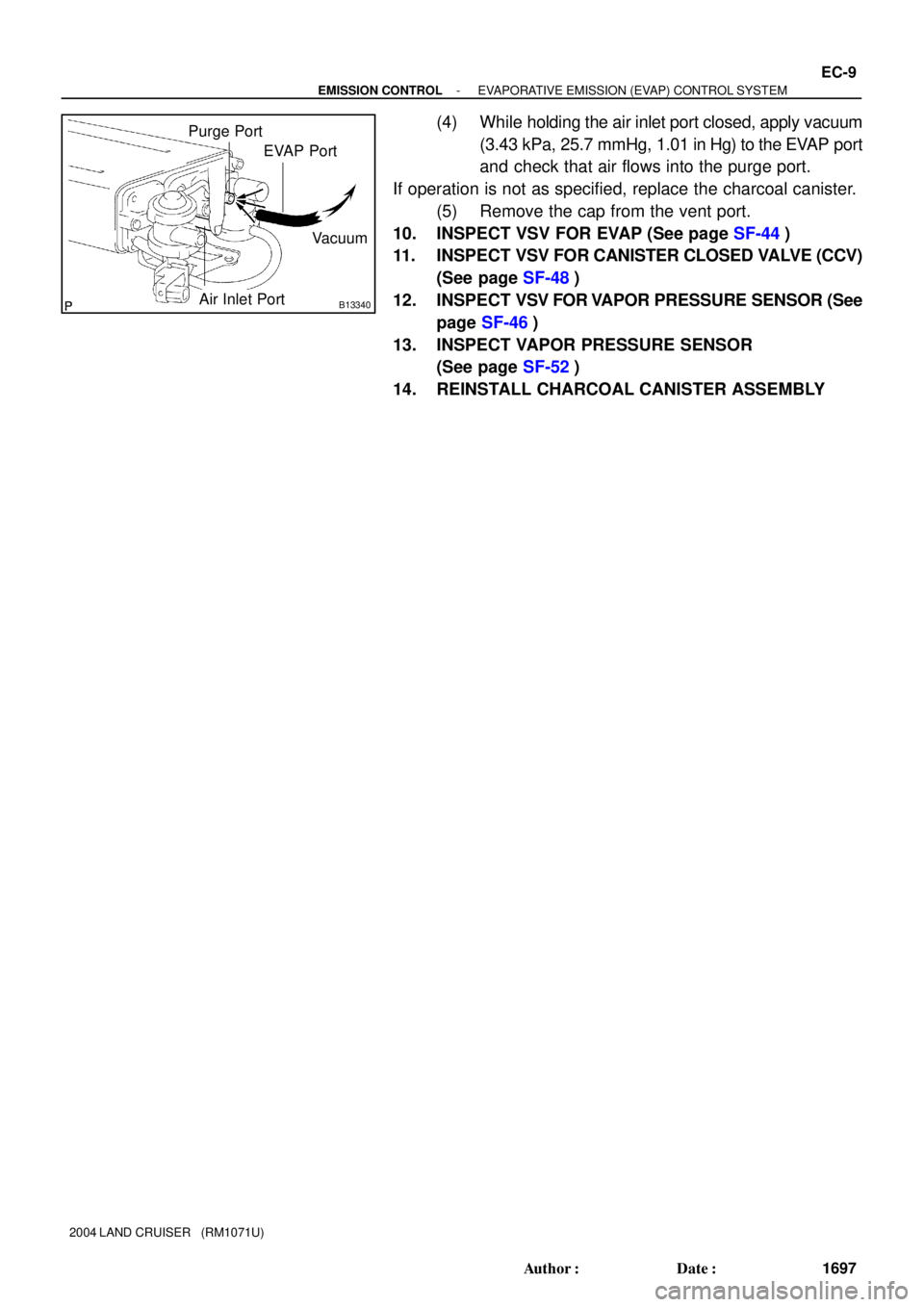
B13340
EVAP Port
Air Inlet PortVacuum Purge Port
- EMISSION CONTROLEVAPORATIVE EMISSION (EVAP) CONTROL SYSTEM
EC-9
1697 Author�: Date�:
2004 LAND CRUISER (RM1071U)
(4) While holding the air inlet port closed, apply vacuum
(3.43 kPa, 25.7 mmHg, 1.01 in Hg) to the EVAP port
and check that air flows into the purge port.
If operation is not as specified, replace the charcoal canister.
(5) Remove the cap from the vent port.
10. INSPECT VSV FOR EVAP (See page SF-44)
11. INSPECT VSV FOR CANISTER CLOSED VALVE (CCV)
(See page SF-48)
12. INSPECT VSV FOR VAPOR PRESSURE SENSOR (See
page SF-46)
13. INSPECT VAPOR PRESSURE SENSOR
(See page SF-52)
14. REINSTALL CHARCOAL CANISTER ASSEMBLY
Page 1788 of 3115
EC07J-08
B16805
Vapor
Pressure
Sensor
Charcoal
Canister
VSV for EVAP
TWCTWC EVAP Service Port
Purge Line
EVAP Line
Air Drain Hose Air Inlet LineVSV for Pressure
Switching ValveVSV for Canister Closed Valve
(CCV)
- EMISSION CONTROLPARTS LAYOUT AND SCHEMATIC DRAWING
EC-3
1691 Author�: Date�:
2004 LAND CRUISER (RM1071U)
DRAWING
Page 1790 of 3115
EC07M-02
B03194
� Heated Oxygen Sensor
(Bank 2 Sensor 2)
� Gasket
TWC
� Gasket
� Gasket
20 (200, 14)
�62 (632, 46)
40 (408, 30)
Heated Oxygen Sensor
(Bank 1 Sensor 2)
� Gasket
�20 (200, 14)
� Gasket
N´m (kgf´cm, ft´lbf)� Gasket
�
: Specified torque
� Non-reusable part�
�
�
� �
� �
�
�
LH Front Exhaust PipeTWC
40 (408, 30)
62 (632, 46)
�
TWC
RH Front Exhaust Pipe
TWC
EC-10- EMISSION CONTROLTHREE-W AY CATALYTIC CONVERTER (TWC)
SYSTEM
1698 Author�: Date�:
2004 LAND CRUISER (RM1071U)
THREE-W AY CATALYTIC CONVERTER (TWC) SYSTEM
COMPONENTS
Page 1793 of 3115
EM-2
- ENGINE MECHANICALCO/HC
1575 Author�: Date�:
2004 LAND CRUISER (RM1071U)
6. TROUBLESHOOTING
HINT:
If the CO/HC concentration does not comply with the regula-
tions, perform troubleshooting in the order given below.
See the table below for possible causes, and then inspect and
correct the applicable causes if necessary.
COHCProblemsCauses
NormalHighRough idle1. Faulty ignitions:
� Incorrect timing
� Fouled, shorted or improperly gapped plugs
2. Incorrect valve clearance
3. Leaky intake and exhaust valves
4. Leaky cylinders
LowHighRough idle
(fluctuating HC reading)1. Vacuum leaks:
� PCV hoses
� Intake manifold
� Throttle body
� Brake booster line
2. Lean mixture causing misfire
HighHighRough idle
(Black smoke from exhaust)1. Restricted air filter
2.Faulty SFI systems:
� Faulty pressure regulator
� Defective ECT sensor
� Faulty ECM
� Faulty injectors
� Faulty throttle position sensor
� Faulty MAF meter
Page 1795 of 3115

EM0E9-15
A05111
Engine Mounting Bracket
Oil Pump
Crankshaft
Front Oil
Seal
Crankshaft Position
Sensor Connector
No.1 Oil Pan
Drain Plug
� Non-reusable part
� Precoated partEngine Wire
Oil StrainerEngine
Mounting
BracketStarter
Cable
Knock
Sensor 2
Connector Knock
Sensor 1Knock
Sensor 2
Engine Coolant Drain UnionStarter
No.2 Oil Pan Oil Pan Baffle Platex 8 Water Pump
� Gasket � O-Ring
Engine
Wire
Engine
Wire
CoverKnock
Sensor 1
Connector Engine Coolant
Drain Union
45 (450, 33)
36 (370, 27)
30.5 (310, 22)
15.5 (160, 11)
28 (290, 31)
x 5
Oil Pressure
Sender Gauge
Connector
7.5 (80, 66 in.´lbf)
7.5 (80, 66 in.´lbf)
7.5 (80, 66 in.´lbf)
N´m (kgf´cm, ft´lbf) : Specified torque �
�
x 20
Ground
Cable
Clamp
Engine Wire
Protector
� Tape
28 (290, 31)
� Gasket
7.5 (80, 66 in.´lbf)
28 (290, 31)
7.5 (80, 66 in.´lbf)
Water Bypass Pipe
Oil Cooler Pipe
Bracket for A/T
7.5 (80, 66 in.´lbf)
� O-Ring
Starter
Connector
� Gasket
EM-86
- ENGINE MECHANICALCYLINDER BLOCK
1659 Author�: Date�:
2004 LAND CRUISER (RM1071U)
CYLINDER BLOCK
COMPONENTS
Page 1797 of 3115

DISASSEMBLY
1. INSTALL ENGINE TO ENGINE")
EM0L6-03
A05112
Pull
Wire
Clamp
O-Ring
A05110
LH Side
A05109
RH Side EM-88
- ENGINE MECHANICALCYLINDER BLOCK
1661 Author�: Date�:
2004 LAND CRUISER (RM1071U)
DISASSEMBLY
1. INSTALL ENGINE TO ENGINE STAND
2. REMOVE TIMING BELT AND PULLEYS
(See page EM-15)
3. REMOVE CYLINDER HEAD (See page EM-35)
4. REMOVE WATER BYPASS PIPE
(a) Disconnect the wire clamp (for knock sensor 1, 2) from the
bracket of the water bypass pipe.
(b) Remove the bolt.
(c) Pull out the water bypass pipe from the water pump.
(d) Remove the O-ring from the water bypass pipe.
5. REMOVE STARTER (See page ST-5)
6. REMOVE KNOCK SENSORS (See page SF-55)
7. DISCONNECT ENGINE WIRE FROM LH SIDE OF CYL-
INDER BLOCK
(a) Remove the 2 bolts and the engine wire cover from the LH
side of the cylinder block.
(b) Remove the bolt, disconnect the bracket on the engine
wire from the cylinder block.
8. DISCONNECT ENGINE WIRE FROM RH SIDE OF CYL-
INDER BLOCK
Remove the 2 bolts, and disconnect the 2 brackets on the en-
gine wire from the cylinder block.
9. REMOVE OIL COOLER PIPE BRACKET FOR A/T
Remove the bolt and bracket.
10. REMOVE ENGINE MOUNTING BRACKETS
Remove the 4 bolts and the mounting bracket. Remove the 2
mounting brackets
11. REMOVE WATER PUMP (See page CO-6)
12. REMOVE NO.2 OIL PAN (See page LU-8)
13. REMOVE OIL PAN BAFFLE PLATE
14. REMOVE NO.1 OIL PAN (See page LU-8)
15. REMOVE OIL STRAINER
16. REMOVE OIL PUMP (See page LU-8)
17. REMOVE ENGINE COOLANT DRAIN UNIONS
Remove the 2 drain unions.