Page 1819 of 3115

(b) Install the 2 drain un")
A04856
FrontPort
A05110
LH Side
A05109
RH Side
A05132
Push
Wire
Clamp
New
O-Ring
- ENGINE MECHANICALCYLINDER BLOCK
EM-1 13
1686 Author�: Date�:
2004 LAND CRUISER (RM1071U)
(b) Install the 2 drain unions.
Torque: 49 N´m (500 kgf´cm, 36 ft´lbf)
HINT:
After applying the specified torque, rotate the drain union clock-
wise until the drain port is facing forward.
16. INSTALL OIL PUMP (See page LU-15)
17. INSTALL OIL STRAINER (See page LU-15)
18. INSTALL NO.1 OIL PAN (See page LU-15)
19. INSTALL OIL PAN BAFFLE PLATE
(See page LU-15)
20. INSTALL NO.2 OIL PAN (See page LU-15)
21. INSTALL WATER PUMP (See page CO-8)
22. INSTALL ENGINE MOUNTING BRACKETS
Install the mounting bracket with the 4 bolts. Install the 2 mount-
ing brackets.
Torque: 36 N´m (370 kgf´cm, 27 ft´lbf)
23. INSTALL ENGINE WIRE TO LH SIDE OF CYLINDER
BLOCK
(a) Install the bracket on the engine wire with the bolt.
(b) Install the engine wire cover with the 2 bolts.
24. INSTALL ENGINE WIRE TO RH SIDE OF CYLINDER
BLOCK
Install the 2 brackets on the engine wire with the 2 bolts.
25. INSTALL OIL COOLER PIPE BRACKET FOR A/T
Install the bracket with the bolt.
26. INSTALL KNOCK SENSORS (See page SF-55)
27. INSTALL STARTER (See page ST-17)
28. INSTALL WATER BYPASS PIPE
(a) Install a new O-ring to the water bypass pipe.
(b) Apply soapy water to the O-ring.
(c) Push the water bypass pipe end into the pipe hole of the
water pump.
(d) Install the water bypass pipe with the bolt.
Torque: 18 N´m (185 kgf´cm, 13 ft´lbf)
(e) Install the wire clamp to the bracket of the water bypass
pipe.
29. INSTALL CYLINDER HEADS (See page EM-59)
Page 1825 of 3115
A19471
� Gasket
� Gasket20 (200, 14)�
40 (400, 30)�
Heated Oxygen Sensor
(Bank 2 Sensor 1)
RH Front Exhaust Pipe� Gasket
LH Front Exhaust Pipe
Heated Oxygen Sensor
(Bank 1 Sensor 1)
20 (200, 14)�
� Gasket
� Gasket
� Gasket
� Non-reusable part
N´m (kgf´cm, ft´lbf) : Specified torquePS Pump
Oil Dipstick and
Guide for A/T
62 (632, 46)�
40 (400, 30)�
62 (632, 46)
62 (632, 46)�
- ENGINE MECHANICALCYLINDER HEAD
EM-29
1602 Author�: Date�:
2004 LAND CRUISER (RM1071U)
Page 1826 of 3115
A04460
RH No. 3 Timing Belt Cover
No. 2 Timing
Belt Cover
LH No. 3 Timing Belt Cover Drive Belt Idler Pulley
Camshaft Position
Sensor ConnectorCover Plate
Engine Wire
16 (160, 12)
7.5 (80, 16 in.´lbf)
N´m (kgf´cm, ft´lbf) : Specified torque
Oil Cooler PipeWire Grommet
39 (400, 29)
7.5 (80, 66 in.´lbf)
Camshaft Position Sensor
A04327
Timing BeltRH Camshaft Timing Pulley
LH Camshaft Timing Belt Pulley
Timing Belt Tensioner
Fan BracketDust Boot
108 (1,100, 80)
245 (2,500, 181)
16 (160, 12)
32 (330, 24)26 (270, 19)N´m (kgf´cm, ft´lbf) : Specified torque
EM-30
- ENGINE MECHANICALCYLINDER HEAD
1603 Author�: Date�:
2004 LAND CRUISER (RM1071U)
Page 1827 of 3115
A19470
EVAP Hose EVAP PipeRear Water
Bypass Joint
Engine Wire
� Gasket
Injection Connector
Fuel Inlet Hose
Ignition Coil
Connector
Ignition Coil Throttle Control
Connector
Water Bypass
Hose
ECT
Sensor Connector
Front Water
Bypass Joint
Water Inlet and Inlet
Housing AssemblyWater Bypass Hose Water
Sender Gauge
LH No.1 Timing Belt Rear Plate
� Non-reusable partEngine WireEngine Wire
� Gasket
� O-Ring
RH No.1 Timing
Belt Rear PlateEVAP Hose
Engine Wire
� GasketHeater
Hose V-Bank Cover
Bracket
V-Bank Cover
BracketPS Hose
VSV Connector
for EVAP Fuel Return Hose
V-Bank Cover
Bracket
Engine Wire
EVAP VSV Hose
Heater Hose
Wire Bracket
- ENGINE MECHANICALCYLINDER HEAD
EM-31
1604 Author�: Date�:
2004 LAND CRUISER (RM1071U)
Page 1829 of 3115

A05561
RH Cylinder Head CoverSpark Plug
LH Cylinder Head
Cover
Gasket
RH Intake Camshaft
RH Exhaust Camshaft Bearing Cap
Bearing CapOil Feed
Pipe
Camshaft Sub Gear Engine Hanger
Heated Oxygen Sensor
(Bank 1 Sensor 1) Connector � RH Cylinder
Head Gasket Engine Wire Bracket
7.5 (77, 66 in.´lbf)
16 (160,12)
Heated Oxygen Sensor
(Bank 2 Sensor 1)
Connector RH Cylinder Head and
Exhaust Manifold AssemblyCamshaft
Housing
Plug Snap Ring
Wave WasherBearing Cap
Oil Seal � Oil Seal
� Non-reusable part
N´m (kgf´cm, ft´lbf) : Specified torque
See page EM-59
1st 32 (326, 24)
2nd Turn 90°
3rd Turn 90°
Semi-Circular
Plug Camshaft Sub GearCamshaft Gear Spring� Spark Plug
Tube Gasket
Gasket
LH Intake
Camshaft
LH Exhaust
Camshaft
Camshaft Gear SpringSnap Ring
Wave Washer
Camshaft Housing Plug
Semi-Circular Plug
Engine Wire
Bracket
Engine
Hanger
� LH Cylinder
Head Gasket
� O-Ring
Oil Dipstick and Guide
for Engine
LH Cylinder Head and
Exhaust Manifold
Assembly
Engine Wire
Protector
7.5 (77, 66 in.´lbf)
- ENGINE MECHANICALCYLINDER HEAD
EM-33
1606 Author�: Date�:
2004 LAND CRUISER (RM1071U)
Page 1853 of 3115

(r) Connect the PS air hose to intake manifold.
(s) Connect the No.1 wat")
B15320B16469No. 1 Water Bypass Hose
EM-70
- ENGINE MECHANICALCYLINDER HEAD
1643 Author�: Date�:
2004 LAND CRUISER (RM1071U)
(r) Connect the PS air hose to intake manifold.
(s) Connect the No.1 water bypass hose (from water inlet
housing) to throttle body.
(t) Connect the throttle control connector.
(u) Connect the VSV connector for EVAP.
(v) Connect the 8 injector connectors.
(w) Connect the ECT sensor.
(x) Connect the water sender gauge.
(y) Connect the 8 ignition coil connectors.
(z) Connect the 2 oxygen sensor connectors.
19. CONNECT FUEL INLET HOSE (See page SF-24)
20. INSTALL TIMING BELT REAR PLATES
(a) Install the RH timing belt rear plates.
Install the No.1 timing belt rear plate to the cylinder head
with the 3 bolts and the stud bolt.
Torque: 7.5 N´m (80 kgf´cm, 66 in.´lbf)
(b) Install the LH timing belt rear plates.
(1) Connect the wire clamp to the No.1 timing belt rear
plate.
(2) Install the No.1 timing belt rear plate to the cylinder
head with the 3 bolts.
Torque: 7.5 N´m (80 kgf´cm, 66 in.´lbf)
21. INSTALL V-BANK COVER
Install the 3 V-bank covers.
Torque: 7.5 N´m (80 kgf´cm, 66 in.´lbf)
22. INSTALL IGNITION COILS (See page IG-6)
23. INSTALL OIL DIPSTICK AND GUIDE FOR A/T
24. INSTALL FRONT EXHAUST PIPE (See page EM-1 15)
25. INSTALL PS PUMP (See page EM-81)
26. INSTALL CAMSHAFT POSITION SENSOR (See page
IG-10)
27. INSTALL CAMSHAFT TIMING PULLEYS
(See page EM-22)
28. CONNECT TIMING BELT TO CAMSHAFT TIMING PUL-
LEYS (See page EM-22)
29. CHECK ENGINE OIL LEVEL
Page 1856 of 3115

REMOVAL
1. DRAIN ENGINE COOLANT
2. REMOVE V-BANK COVER
Remove the V-bank covers.
3. DISCONNECT")
EM1V8-01
A02844
- ENGINE MECHANICALCYLINDER HEAD
EM-35
1608 Author�: Date�:
2004 LAND CRUISER (RM1071U)
REMOVAL
1. DRAIN ENGINE COOLANT
2. REMOVE V-BANK COVER
Remove the V-bank covers.
3. DISCONNECT TIMING BELT FROM CAMSHAFT TIM-
ING PULLEYS (See page EM-15)
4. REMOVE CAMSHAFT TIMING PULLEYS (See page
EM-15)
5. REMOVE CAMSHAFT POSITION SENSOR (See page
IG-9)
6. DISCONNECT PS PUMP FROM ENGINE
(See page EM-77)
7. REMOVE FRONT EXHAUST PIPE (See page EM-1 15)
8. REMOVE OIL DIPSTICK AND GUIDE FOR A/T
9. REMOVE IGNITION COILS (See page IG-6)
10. REMOVE TIMING BELT REAR PLATES
(1) Remove the 3 bolts, the stud bolt, and the RH No.1
timing belt rear plates.
(2) Disconnect the wire clamp from the LH timing belt
rear plate.
(3) Remove the 3 bolts, the stud bolt, the LH No.1 and
the timing belt rear plates.
NOTICE:
�Be careful not to drop anything inside the timing belt
cover.
�Do not allow the belt to contact correct with oil, water
or dust.
11. DISCONNECT FUEL INLET HOSE (See page SF-24)
12. REMOVE INTAKE MANIFOLD ASSEMBLY
(a) Disconnect the throttle control connector.
(b) Disconnect the VSV connector for EVAP.
(c) Disconnect the 8 injector connectors.
(d) Disconnect the ECT sensor connector.
(e) Disconnect the water sender gauge connector.
(f) Disconnect the 8 ignition coil connectors.
(g) Disconnect the 2 oxygen sensor connectors.
Page 1871 of 3115
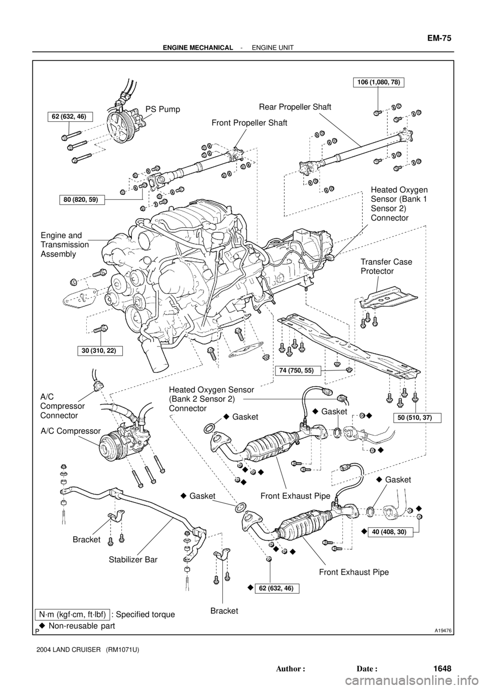
A19476
Front Propeller Shaft
Transfer Case
Protector PS Pump
Engine and
Transmission
Assembly
Rear Propeller Shaft
Bracket A/C
Compressor
Connector� Gasket
Heated Oxygen Sensor
(Bank 2 Sensor 2)
Connector
� Gasket
Front Exhaust Pipe � Gasket
Stabilizer Bar Bracket A/C Compressor
50 (510, 37)
106 (1,080, 78)
62 (632, 46)
40 (408, 30)
N´m (kgf´cm, ft´lbf) : Specified torque
� Non-reusable part
80 (820, 59)
Heated Oxygen
Sensor (Bank 1
Sensor 2)
Connector
30 (310, 22)
Front Exhaust Pipe� Gasket
���� �
��
��
�
62 (632, 46)
74 (750, 55)
- ENGINE MECHANICALENGINE UNIT
EM-75
1648 Author�: Date�:
2004 LAND CRUISER (RM1071U)


7.5 (80, 16 in.´lbf")