Page 1179 of 3115

DI-130
- DIAGNOSTICSENGINE
323 Author�: Date�:
2004 LAND CRUISER (RM1071U)
MONITOR STRATEGY
RltdDTCP0134Excessive time to enter closed loop (Bank 1)Related DTCsP0154Excessive time to enter closed loop (Bank 2)
Main sensors/componentsFront heated oxygen sensor
Required sensors/componentsRelated sensors/componentsCrank position sensor, Engine coolant tempera-
ture sensor, Vehicle speed sensor
Frequency of operationOnce per drive cycle
Duration65 sec.
MIL operation1 driving cycle
Sequence of operationNone
TYPICAL ENABLING CONDITIONS
ItSpecificationItemMinimumMaximum
The monitor will run whenever the follow-
ing DTCs are not presentSee ºList of disable a monitorº (on page DI-3)
Both of the following conditions were metA and B
A. Time after following conditions met for
50 sec.(a), (b), (c), (d), (e) and (f)
(a) Engine coolant temperature40�C (104°F)-
(b) Engine speed1,400 rpm-
(c) Vehicle speed40 km/h (25 mph)-
(d) IdleOFF
(e) Time after engine start180 sec.-
(f) Fuel enrichment correction factor163.998
B. Neither fail nor pass is determined yet in the present drive cycle
TYPICAL MALFUNCTION THRESHOLDS
Detection CriteriaThreshold
Front heated oxygen sensor voltageLess than 0.45 V
COMPONENT OPERATING RANGE
ParameterStandard value
In the normal condition, the front heated oxygen sensor
voltage0 to 1 V
WIRING DIAGRAM
Refer to DTC P0031 on page DI-49.
Page 1190 of 3115

A20316
Vehicle speed
40 km/h
(25 mph)
IG SW OFFOnce
40 sec.
or more
60 sec.
or more10 sec.Twice
40 sec.
or more12 times
40 sec.
or more
10 sec. 10 sec.
(�1)(�3)
(�4)
Idling(�2)(�3)
(�4)(�3)
(�4)
- DIAGNOSTICSENGINE
DI-141
334 Author�: Date�:
2004 LAND CRUISER (RM1071U)
Rear HO2S element monitor
If all the values ($81, $84, $85 and $87) are out of the standard values, the ECM interprets this as a malfunc-
tion.
TEST IDDescription of TEST DATAConversion FactorUnit
$81
Percentage of monitoring time
when the HO2S voltage is less
than 0.05 V
Multiply 0.3906%
$84
Percentage of monitoring time
when the HO2S voltage is more
than 0.7 V
Multiply 0.3906%
$85Time when the HO2S voltage is
0.45 V or moreMultiply 0.2621sec.
$87
Percentage of monitoring time
when the HO2S voltage is 0.45 V
or more
Multiply 0.3906%
WIRING DIAGRAM
Refer to DTC P0031 on page DI-49.
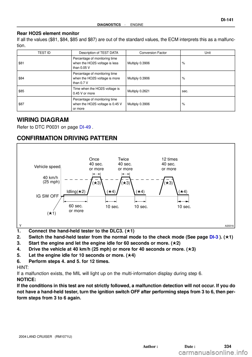
CONFIRMATION DRIVING PATTERN
1. Connect the hand-held tester to the DLC3. (�1)
2. Switch the hand-held tester from the normal mode to the check mode (See page DI-3). (�1)
3. Start the engine and let the engine idle for 60 seconds or more. (�2)
4. Drive the vehicle at 40 km/h (25 mph) or more for 40 seconds or more. (�3)
5. Let the engine idle for 10 seconds or more. (�4)
6. Perform steps 4. and 5. for 12 times.
HINT:
If a malfunction exists, the MIL will light up on the multi-information display during step 6.
NOTICE:
If the conditions in this test are not strictly followed, a malfunction detection will not occur. If you do
not have a hand-held tester, turn the ignition switch OFF after performing steps from 3 to 6, then per-
form steps from 3 to 6 again.
Page 1198 of 3115

- DIAGNOSTICSENGINE
DI-149
342 Author�: Date�:
2004 LAND CRUISER (RM1071U)
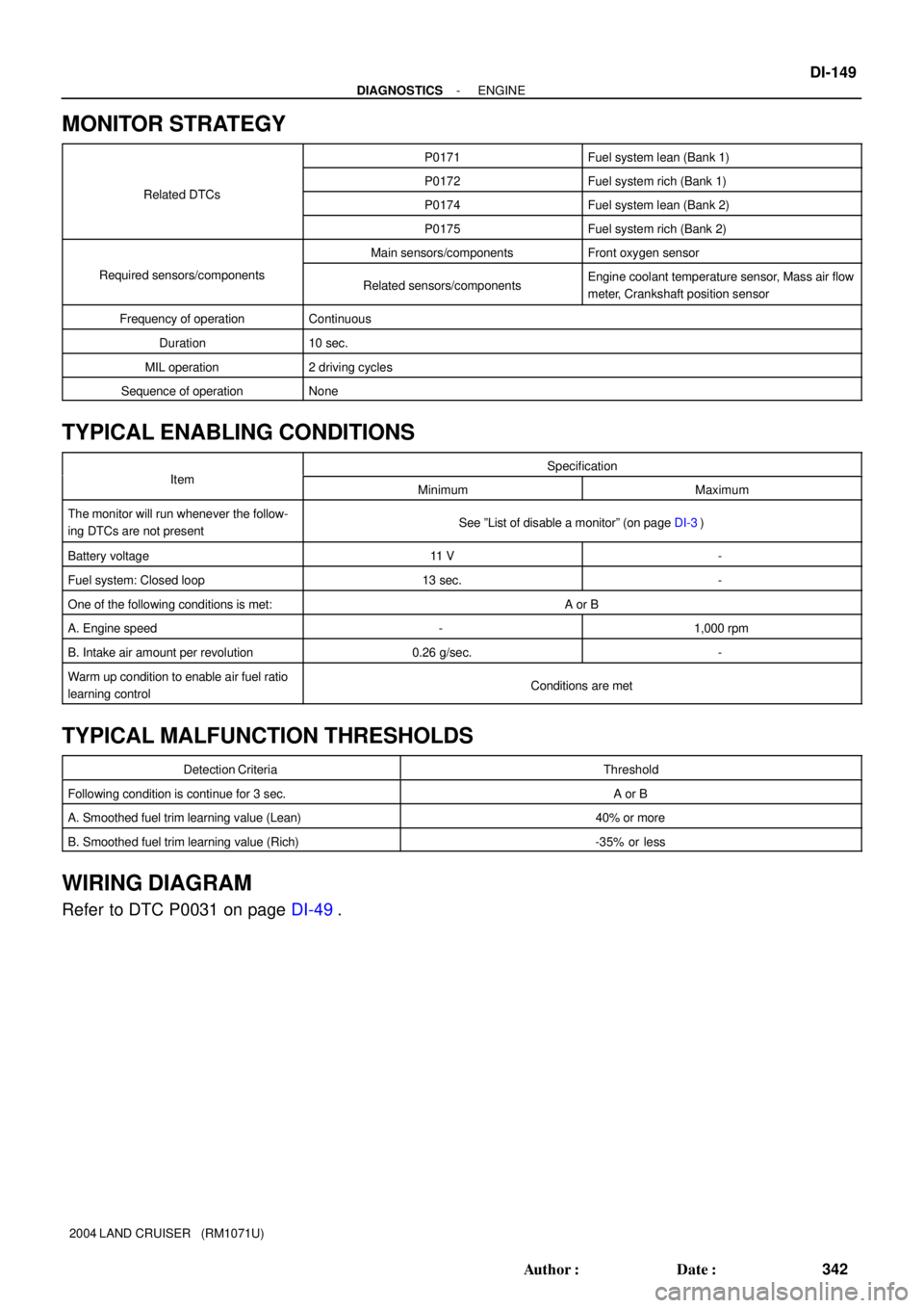
MONITOR STRATEGY
P0171Fuel system lean (Bank 1)
RltdDTCP0172Fuel system rich (Bank 1)Related DTCsP0174Fuel system lean (Bank 2)
P0175Fuel system rich (Bank 2)
Main sensors/componentsFront oxygen sensor
Required sensors/componentsRelated sensors/componentsEngine coolant temperature sensor, Mass air flow
meter, Crankshaft position sensor
Frequency of operationContinuous
Duration10 sec.
MIL operation2 driving cycles
Sequence of operationNone
TYPICAL ENABLING CONDITIONS
ItSpecificationItemMinimumMaximum
The monitor will run whenever the follow-
ing DTCs are not presentSee ºList of disable a monitorº (on page DI-3)
Battery voltage11 V-
Fuel system: Closed loop13 sec.-
One of the following conditions is met:A or B
A. Engine speed-1,000 rpm
B. Intake air amount per revolution0.26 g/sec.-
Warm up condition to enable air fuel ratio
learning controlConditions are met
TYPICAL MALFUNCTION THRESHOLDS
Detection CriteriaThreshold
Following condition is continue for 3 sec.A or B
A. Smoothed fuel trim learning value (Lean)40% or more
B. Smoothed fuel trim learning value (Rich)-35% or less
WIRING DIAGRAM
Refer to DTC P0031 on page DI-49.
Page 1213 of 3115
A19965A20085
ECM
FPR
FC
MREL Engine Room R/B
Engine Room J/B
Cowl Side J/B RH Cowl Side J/B LH
I18
Ignition SW
Cowl Side J/B LHJ/B No. 5
J4
J/C
MAINJ/B No. 6
F15
FL Block Fuel Pump
Relay
C/OPN Relay
EFI or ECD Relay
EFI or ECD No. 1
AM2
IGN
Battery 1
1
1
1
1
111 1 1 1 1 1
1 2 35 4
3
125
1
2 3
4 R-L
R-L
R-LB
BB
IA29
BB1
2
G-W6D
6C710
G-W
B-Y
B-Y
W-BG-W
B-W
B-WF12
Fuel
Pump
1
4
2 16
13
155C 5D
5C 5D
5C 5D B-R
B-Y
B-W
B-YM4
5 B
W-B33
E5
10
8 E9
E9
BB1 8
W-B 1A
1B
1B
1B 1C1 9 11 44 43
422
3E3B
AA B-R
B-RB-R
6 7
2K 2A 2E W-R W-R
B-G
W-B
33
IF EAB-W
B-W
F14 Fuel Pump
Resistor
L-B
4110
2 IG2 AM2If113
G-WG-W 12
DI-164
- DIAGNOSTICSENGINE
357 Author�: Date�:
2004 LAND CRUISER (RM1071U)
WIRING DIAGRAM
HINT:
This diagnostic chart is based on premise that engine is started. If the engine is not started, proceed to prob-
lem symptoms table on DI-48.
Page 1220 of 3115

A19966
Battery I18
Ignition SW
#8#6 #4 #2
#7 #5ECM
#3 #1
7
5 2 1
4
3 3
1C1 F15
FL BlockEngine Room J/B
1B 6Cowl Side J/B LH
6
E7
E7 E6E5
Y
W G R
IG2
AM2E5 E5 E5 E5
5 I9
Injector No. 1
I16
Injector No. 8 I15
Injector No. 7 I14
Injector No. 6 I13
Injector No. 5 I12
Injector No. 4 I11
Injector No. 3 I10
Injector No. 2
AAJ4
J/C
Ib2 IN2712
AM22E 41
2A 10
9
2B-G
MAIN
B-W R-LL B 12
12 12 12
12 12 12 12
W-R W-R W-R B-R B-R B-R B-RB-R
B-R B-RB-R B-R B-R B-R B-R
B-RB-RB-R B-R B-R
- DIAGNOSTICSENGINE
DI-171
364 Author�: Date�:
2004 LAND CRUISER (RM1071U)
TYPICAL MALFUNCTION THRESHOLDS
Detection CriteriaThreshold
Emission related misfire rate:
1. During the first 1,000 revolutions after engine start
(MIL is set when misfire is detected 1 time)
2. After the first 1,000 revolutions have occurred
(MIL is set when misfire is detected 4 times)
3 %/1,000 revolutions
Catalyst damage misfire count:
1. Low engine rpm area (ex. less than 3,000 rpm):
200 revolutions (MIL is set when misfire is detected 3
times)
2. High engine rpm area: Every 200 revolutions
96 count/200 revolutions
(Threshold varies with engine speed and intake air amount per revolution)
WIRING DIAGRAM
Refer to DTC P0351 on page DI-202 for the wiring diagram of the ignition system.
Page 1237 of 3115
A19967A20086
ECM
KNK1 1
E6 B2 K1
Knock Sensor 1
1
K2
Knock Sensor 21
2
KNK2 E6 EC1
EC *1: Shielded(*1)
3 EC1
W(*1)
B
W
J17
J/C
E
D
BRE
E
DBR
J17
J/C DI-188
- DIAGNOSTICSENGINE
381 Author�: Date�:
2004 LAND CRUISER (RM1071U)
WIRING DIAGRAM
Page 1242 of 3115
A19968
C1
Camshaft Position Sensor
C3
Crankshaft Position SensorRECM
NE+
NE-
E2 27
2 12 1
25
24
GE7
G2+
G2-
32
E7
E7
E7 (Shielded)
E7
E1
ECBR1
DD EE E L G (Shielded)
J17
J/C
BR
BR
- DIAGNOSTICSENGINE
DI-193
386 Author�: Date�:
2004 LAND CRUISER (RM1071U)
WIRING DIAGRAM
Page 1248 of 3115

A21026
Component Side
Camshaft Position Sensor C1
- DIAGNOSTICSENGINE
DI-199
392 Author�: Date�:
2004 LAND CRUISER (RM1071U)
COMPONENT OPERATING RANGE
ParameterStandard Value
Camshaft position sensor signal input during every 720�CA3
WIRING DIAGRAM
Refer to DTC P0335 on page DI-191.
INSPECTION PROCEDURE
HINT:
Read freeze frame data using the hand-held tester or the OBD II scan tool. Freeze frame data records the
engine conditions when a malfunction is detected. When troubleshooting, freeze frame data can help deter-
mine if the vehicle was running or stopped, if the engine was warmed up or not, if the air-fuel ratio was lean
or rich, as well as other data from the time when a malfunction occurred.
1 Check resistance of camshaft position sensor.
PREPARATION:
Disconnect the C1 camshaft position sensor connector.
CHECK:
Measure the resistance between terminals 1 and 2.
OK:
Tester ConnectionSpecified Condition
121,630 to 2,740 W at cold1 - 22,065 to 3,225 W at hot
NOTICE:
º Coldº and ºHotº shown above mean the temperature of
the coils themselves. ºColdº is from -10°C (14°F) to 50°C
(122°F) and ºHotº is from 50°C (122°F) to 100°C (212°F).
NG Replace camshaft position sensor.
OK