Page 982 of 3115
D12766
S1 R
E6 W E1
Electronically Controlled
Transmission Solenoid
11ECM
R8
S18EB2
- DIAGNOSTICSAUTOMATIC TRANSMISSION
DI-461
654 Author�: Date�:
2004 LAND CRUISER (RM1071U)
TYPICAL MALFUNCTION THRESHOLDS
Detection criteriaThreshold
Range check (Low resistance)
Intelligent power MOS diagnosis fail signals detected while
the solenoid is operatedFail at solenoid resistance: 8 W or less
Range check (High resistance)
Intelligent power MOS diagnosis fail signals detected while
the solenoid is not operatedFail at solenoid resistance: 100 kW or more
COMPONENT OPERATING RANGE
ParameterStandard value
Shift solenoid valve S1Resistance: 11 to 15 W at 20°C (68°F)
WIRING DIAGRAM
Page 986 of 3115
D12766
S2 W
E6 B10
15ECM
E1
Electronically Controlled
Transmission Solenoid
W9
EB2
S2
- DIAGNOSTICSAUTOMATIC TRANSMISSION
DI-465
658 Author�: Date�:
2004 LAND CRUISER (RM1071U)
TYPICAL MALFUNCTION THRESHOLDS
Detection criteriaThreshold
Range check (Low resistance)
Intelligent power MOS diagnosis fail signal detected while
the solenoid is operatedFail at solenoid resistance: 8 W or less
Range check (High resistance)
Intelligent power MOS diagnosis fail signal detected while
the solenoid is not operatedFail at solenoid resistance: 100 kW or more
COMPONENT OPERATING RANGE
ParameterStandard value
Shift solenoid valve S2Resistance: 11 to 15 W at 20°C (68°F)
WIRING DIAGRAM
Page 990 of 3115
D12766
SR G
E6 SB7
7ECM
E1
Electronically Controlled
Transmission Solenoid
15
G
EB2
SR
- DIAGNOSTICSAUTOMATIC TRANSMISSION
DI-469
662 Author�: Date�:
2004 LAND CRUISER (RM1071U)
TYPICAL MALFUNCTION THRESHOLDS
Detection criteriaThreshold
Range check (Low resistance)
Intelligent power MOS diagnosis fail signals detected while
the solenoid is operatedFail at solenoid resistance: 8 W or less
Range check (High resistance)
Intelligent power MOS diagnosis fail signals detected while
the solenoid is not operatedFail at solenoid resistance: 100 kW or more
COMPONENT OPERATING RANGE
ParameterStandard value
Shift solenoid valve SRResistance: 11 to 15 at 20°C (68°F)
WIRING DIAGRAM
Page 995 of 3115
D12765
ECM
L4 4
E8 EB1 6CJ/B No. 6
115 D5
Detection SW
(Transfer L Position)
J/B No. 3
ALT
II R-LB-L
1
26D31
R-LB-L
EB1B-L 3 11
IN2Ib2 14 6
R-L
R-L3
1
39 3E
3C
3Q
1 23
5 IG1 No. 3 RelayGAUGE2 Cowl Side J/B RH
Cowl Side J/B LHB-G
SB
J/B No. 2
Battery FL Block
1 1
F17 F16 B-G
B-G13937 77
2Q
2C2E
2E AM1I18
Ignition SW
AM1 IG12 4
B-R L-B DI-474
- DIAGNOSTICSAUTOMATIC TRANSMISSION
667 Author�: Date�:
2004 LAND CRUISER (RM1071U)
WIRING DIAGRAM
Page 1001 of 3115
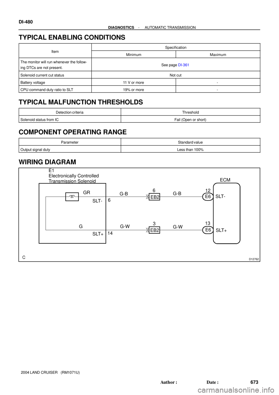
D12762
ECM
SLT+ SLT- G-B
G-W
E6
G12
EB2E6
13 6
14 E1
Electronically Controlled
Transmission Solenoid
G-B
G-W
EB23 6
SLT+ SLT-
GR DI-480
- DIAGNOSTICSAUTOMATIC TRANSMISSION
673 Author�: Date�:
2004 LAND CRUISER (RM1071U)
TYPICAL ENABLING CONDITIONS
ItSpecificationItemMinimumMaximum
The monitor will run whenever the follow-
ing DTCs are not present.See page DI-361
Solenoid current cut statusNot cut
Battery voltage11 V or more-
CPU command duty ratio to SLT19% or more-
TYPICAL MALFUNCTION THRESHOLDS
Detection criteriaThreshold
Solenoid status from ICFail (Open or short)
COMPONENT OPERATING RANGE
ParameterStandard value
Output signal dutyLess than 100%
WIRING DIAGRAM
Page 1005 of 3115

MONITOR DESCRIPTION
The automatic transmission fluid (ATF) temperature sensor converts ATF temperature to a")
DI-484
- DIAGNOSTICSAUTOMATIC TRANSMISSION
677 Author�: Date�:
2004 LAND CRUISER (RM1071U)
MONITOR DESCRIPTION
The automatic transmission fluid (ATF) temperature sensor converts ATF temperature to an electrical resis-
tance value. Based on the resistance, the ECM determines the ATF temperature, and the ECM detects an
opens or shorts in the ATF temperature circuit. If the resistance value of the ATF temperature is less than
79 W or more than 156 kW, the ECM interprets this as a fault in the ATF sensor or wiring. The ECM will turn
on the MIL and store the DTC.
MONITOR STRATEGY
P2740ATF temperature sensor/Range check (Fluttering)
Related DTCsP2742ATF temperature sensor/Range check (Low resistance)Related DTCs
P2743ATF temperature sensor/Range check (High resistance)
Required sensors/ComponentsATF temperature sensor
Frequency of operationContinuous
Duration0.5 sec.
MIL operationImmediate
Sequence of operationNone
TYPICAL ENABLING CONDITIONS
ItSpecificationItemMinimumMaximum
The monitor will run whenever the follow-
ing DTCs are not present.See page DI-361
Range check (Fluttering, Low resistance)
The typical enabling condition is not avail-
able.-
Range check (High resistance)
Time after engine start15 min. or more-
TYPICAL MALFUNCTION THRESHOLDS
Detection criteriaThreshold
Range check (Fluttering)
ATF temperature sensor resistance
Less than 25 W
or
More than 156 kW
Range check (Low resistance)
ATF temperature sensor resistanceLess than 25 W
Range check (High resistance)
ATF temperature sensor resistanceMore than 156 kW
COMPONENT OPERATING RANGE
ParameterStandard value
ATF temperature sensorAtmospheric temperature to approx. 130°C (266°F)
Page 1006 of 3115
D12759
Electronically Controlled
Transmission Solenoid
THO1
Y
1 2
E2ECM
4
28 E1
G-Y
11
10
9THO2
E5 E6E6
L
BR-W Y OO
G-Y
L
BR-W
If1 EB2EB2
OT+
OT2+ OT-
OT2-
EB3 BR-W BR-W BR-W
32432
1
152 3 4 5 6 7 8
9 10 11 12
13 14
D11994OT2+ OT2-
- DIAGNOSTICSAUTOMATIC TRANSMISSION
DI-485
678 Author�: Date�:
2004 LAND CRUISER (RM1071U)
WIRING DIAGRAM
INSPECTION PROCEDURE
1 Check transmission wire.
PREPARATION:
Disconnect the transmission wire connector from the transmis-
sion.
CHECK:
Measure the resistance between terminals OT2+ and OT2-.
OK:
79 W to 156 kW
CHECK:
Measure resistance between terminals OT2+ and OT2- of the
transmission wire connector and body ground.
OK:
Resistance: 1 MW or higher
NG Replace the transmission wire (ATF tempera-
ture sensor).
OK
Page 1013 of 3115
D12762
E1
Electronically Controlled
Transmission SolenoidECM
16 2
EB2 E7
SLU
-
P-G
B 215SLU+LG
EB3E7 P-G
B BRSLU+
SLU- 513 DI-492
- DIAGNOSTICSAUTOMATIC TRANSMISSION
685 Author�: Date�:
2004 LAND CRUISER (RM1071U)
TYPICAL ENABLING CONDITIONS
ItSpecificationItemMinimumMaximum
The monitor will run whenever the follow-
ing DTCs are not present.See page DI-361
Battery voltage10 V or more-
TYPICAL MALFUNCTION THRESHOLDS
Detection criteriaThreshold
Output signal duty100%
COMPONENT OPERATING RANGE
ParameterStandard value
Output signal dutyLess than 100%
WIRING DIAGRAM


J/B No. 3
ALT
II R-LB-L
1
26D31
R-LB-L
EB1B-L 3 11
IN2Ib2 14 6
R-L
R-L3
1
39 3E
3C
3Q
1 23
5 IG1 No. 3 RelayGAUGE2 Cowl S")