Page 387 of 1659
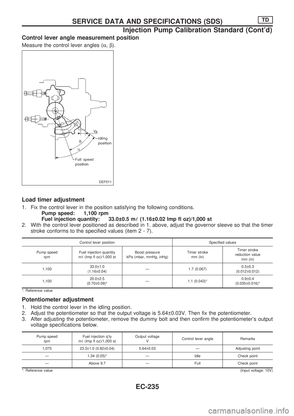
Control lever angle measurement position
Measure the control lever angles (a,b).
Load timer adjustment
1. Fix the control lever in the position satisfying the following conditions.
Pump speed: 1,100 rpm
Fuel injection quantity: 33.0 0.5 m!(1.16 0.02 Imp fl oz)/1,000 st
2. With the control lever positioned as described in 1. above, adjust the governor sleeve so that the timer
stroke conforms to the specified values (item2-7).
Control lever position Specified values
Pump speed
rpmFuel injection quantity
m!(Imp fl oz)/1,000 stBoost pressure
kPa (mbar, mmHg, inHg)Timer stroke
mm (in)Timer stroke
reduction value
mm (in)
1,10033.0 1.0
(1.16 0.04)Ð 1.7 (0.067)0.3 0.3
(0.012 0.012)
1,10020.0 2.5
(0.70 0.09)*Ð 1.1 (0.043)*0.9 0.4
(0.035 0.016)*
*: Reference value
Potentiometer adjustment
1. Hold the control lever in the idling position.
2. Adjust the potentiometer so that the output voltage is 5.64 0.03V. Then fix the potentiometer.
3. After adjusting the potentiometer, remove the dummy bolt and then confirm the potentiometer's output
voltage specifications below.
Pump speed
rpmFuel injection q'ty
m!(Imp fl oz)/1,000 stOutput voltage
VControl lever angle Remarks
1,075 23.3 1.0 (0.82 0.04) 5.64 0.03 Ð Adjusting point
Ð 1.34 (0.05)* Ð Idle Check point
Ð Above 9.7 Ð Full Check point
*: Reference value(Input voltage: 10V)
DEF011
SERVICE DATA AND SPECIFICATIONS (SDS)TD
Injection Pump Calibration Standard (Cont'd)
EC-235
Page 439 of 1659
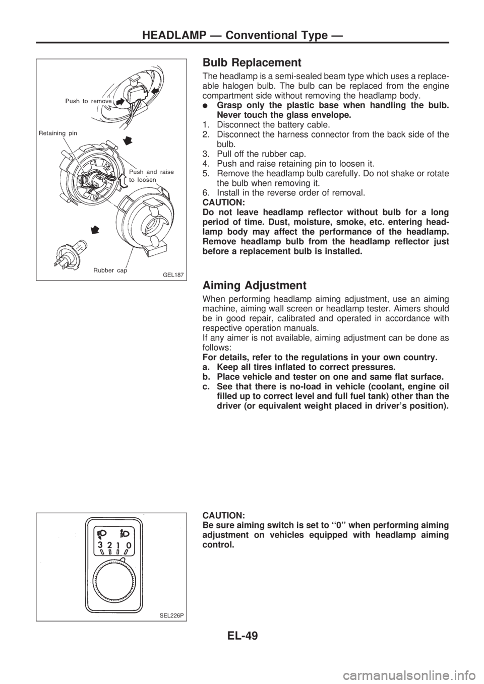
Bulb Replacement
The headlamp is a semi-sealed beam type which uses a replace-
able halogen bulb. The bulb can be replaced from the engine
compartment side without removing the headlamp body.
lGrasp only the plastic base when handling the bulb.
Never touch the glass envelope.
1. Disconnect the battery cable.
2. Disconnect the harness connector from the back side of the
bulb.
3. Pull off the rubber cap.
4. Push and raise retaining pin to loosen it.
5. Remove the headlamp bulb carefully. Do not shake or rotate
the bulb when removing it.
6. Install in the reverse order of removal.
CAUTION:
Do not leave headlamp reflector without bulb for a long
period of time. Dust, moisture, smoke, etc. entering head-
lamp body may affect the performance of the headlamp.
Remove headlamp bulb from the headlamp reflector just
before a replacement bulb is installed.
Aiming Adjustment
When performing headlamp aiming adjustment, use an aiming
machine, aiming wall screen or headlamp tester. Aimers should
be in good repair, calibrated and operated in accordance with
respective operation manuals.
If any aimer is not available, aiming adjustment can be done as
follows:
For details, refer to the regulations in your own country.
a. Keep all tires inflated to correct pressures.
b. Place vehicle and tester on one and same flat surface.
c. See that there is no-load in vehicle (coolant, engine oil
filled up to correct level and full fuel tank) other than the
driver (or equivalent weight placed in driver's position).
CAUTION:
Be sure aiming switch is set to ``0'' when performing aiming
adjustment on vehicles equipped with headlamp aiming
control.
GEL187
SEL226P
HEADLAMP Ð Conventional Type Ð
EL-49
Page 506 of 1659
Electrical Components Inspection
FUEL WARNING LAMP SENSOR CHECK
lIt will take a short time for the bulb to light.
OIL PRESSURE SWITCH CHECK
Oil pressure
kPa (bar, kg/cm2, psi)Continuity
Engine startMore than 10 - 20
(0.10 - 0.20, 0.1 - 0.2,1-3)NO
Engine stopLess than 10 - 20
(0.10 - 0.20, 0.1 - 0.2,1-3)YES
Check the continuity between the terminals of oil pressure switch
and body ground.
DIODE CHECK
lCheck continuity using an ohmmeter.
lDiode is functioning properly if test results are as shown in
the figure at left.
NOTE: Specification may vary depending on the type of
tester. Before performing this inspection, be sure to
refer to the instruction manual for the tester to be
used.
lDiodes for warning lamps are built into the combination meter
printed circuit.
GEL191
MEL425F
SEL901F
GEL192
WARNING LAMPS
EL-116
Page 643 of 1659
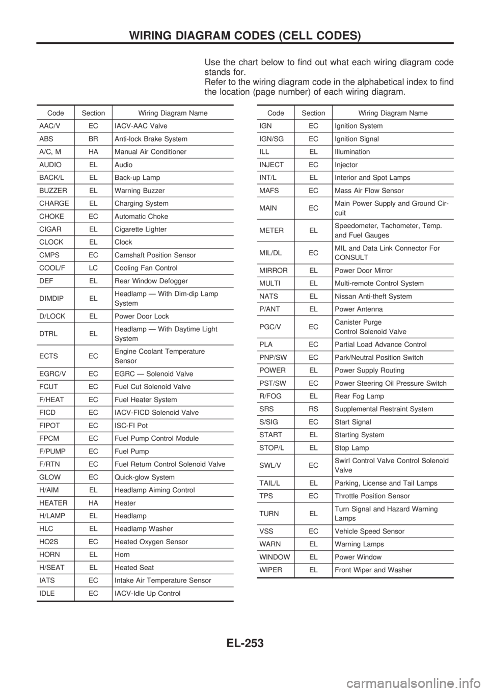
Use the chart below to find out what each wiring diagram code
stands for.
Refer to the wiring diagram code in the alphabetical index to find
the location (page number) of each wiring diagram.
Code Section Wiring Diagram Name
AAC/V EC IACV-AAC Valve
ABS BR Anti-lock Brake System
A/C, M HA Manual Air Conditioner
AUDIO EL Audio
BACK/L EL Back-up Lamp
BUZZER EL Warning Buzzer
CHARGE EL Charging System
CHOKE EC Automatic Choke
CIGAR EL Cigarette Lighter
CLOCK EL Clock
CMPS EC Camshaft Position Sensor
COOL/F LC Cooling Fan Control
DEF EL Rear Window Defogger
DIMDIP ELHeadlamp Ð With Dim-dip Lamp
System
D/LOCK EL Power Door Lock
DTRL ELHeadlamp Ð With Daytime Light
System
ECTS ECEngine Coolant Temperature
Sensor
EGRC/V EC EGRC Ð Solenoid Valve
FCUT EC Fuel Cut Solenoid Valve
F/HEAT EC Fuel Heater System
FICD EC IACV-FICD Solenoid Valve
FIPOT EC ISC-FI Pot
FPCM EC Fuel Pump Control Module
F/PUMP EC Fuel Pump
F/RTN EC Fuel Return Control Solenoid Valve
GLOW EC Quick-glow System
H/AIM EL Headlamp Aiming Control
HEATER HA Heater
H/LAMP EL Headlamp
HLC EL Headlamp Washer
HO2S EC Heated Oxygen Sensor
HORN EL Horn
H/SEAT EL Heated Seat
IATS EC Intake Air Temperature Sensor
IDLE EC IACV-Idle Up ControlCode Section Wiring Diagram Name
IGN EC Ignition System
IGN/SG EC Ignition Signal
ILL EL Illumination
INJECT EC Injector
INT/L EL Interior and Spot Lamps
MAFS EC Mass Air Flow Sensor
MAIN ECMain Power Supply and Ground Cir-
cuit
METER ELSpeedometer, Tachometer, Temp.
and Fuel Gauges
MIL/DL ECMIL and Data Link Connector For
CONSULT
MIRROR EL Power Door Mirror
MULTI EL Multi-remote Control System
NATS EL Nissan Anti-theft System
P/ANT EL Power Antenna
PGC/V ECCanister Purge
Control Solenoid Valve
PLA EC Partial Load Advance Control
PNP/SW EC Park/Neutral Position Switch
POWER EL Power Supply Routing
PST/SW EC Power Steering Oil Pressure Switch
R/FOG EL Rear Fog Lamp
SRS RS Supplemental Restraint System
S/SIG EC Start Signal
START EL Starting System
STOP/L EL Stop Lamp
SWL/V ECSwirl Control Valve Control Solenoid
Valve
TAIL/L EL Parking, License and Tail Lamps
TPS EC Throttle Position Sensor
TURN ELTurn Signal and Hazard Warning
Lamps
VSS EC Vehicle Speed Sensor
WARN EL Warning Lamps
WINDOW EL Power Window
WIPER EL Front Wiper and Washer
WIRING DIAGRAM CODES (CELL CODES)
EL-253
Page 655 of 1659

Measurement of Compression Pressure
1. Warm up engine.
2. Turn ignition switch OFF.
3. Release fuel pressure.
Refer to EC section (``Fuel Pressure Release'', ``BASIC SER-
VICE PROCEDURE'').
4. Remove all spark plugs.
5. Disconnect distributor center cable.
6. Attach a compression tester to No. 1 cylinder.
7. Depress accelerator pedal fully to keep throttle valve wide
open.
8. Crank engine and record highest gauge indication.
9. Repeat the measurement on each cylinder.
lAlways use a fully-charged battery to obtain specified
engine speed.
Compression pressure:
kPa (bar, kg/cm
2, psi)/rpm
Standard
1,324 (13.24, 13.5, 192)/300
Minimum
981 (9.8, 10, 142)/300
Difference limit between cylinders
98 (0.98, 1.0, 14)/300
10. If compression in one or more cylinders is low:
a. Pour a small amount of engine oil into cylinders through
spark plug holes.
b. Retest compression.
lIf adding oil helps compression, piston rings may be
worn or damaged. If so, replace piston rings after check-
ing piston.
lIf pressure stays low, a valve may be sticking or seating
improperly. Inspect and repair valve and valve seat.
(Refer to SDS.) If valve or valve seat is damaged
excessively, replace them.
lIf compression stays low in two cylinders that are next
to each other:
a. The cylinder head gasket may be leaking, or
b. Both cylinders may have valve component damage.
Inspect and repair as necessary.
SEM113B
COMPRESSION PRESSUREKA
EM-10
Page 670 of 1659
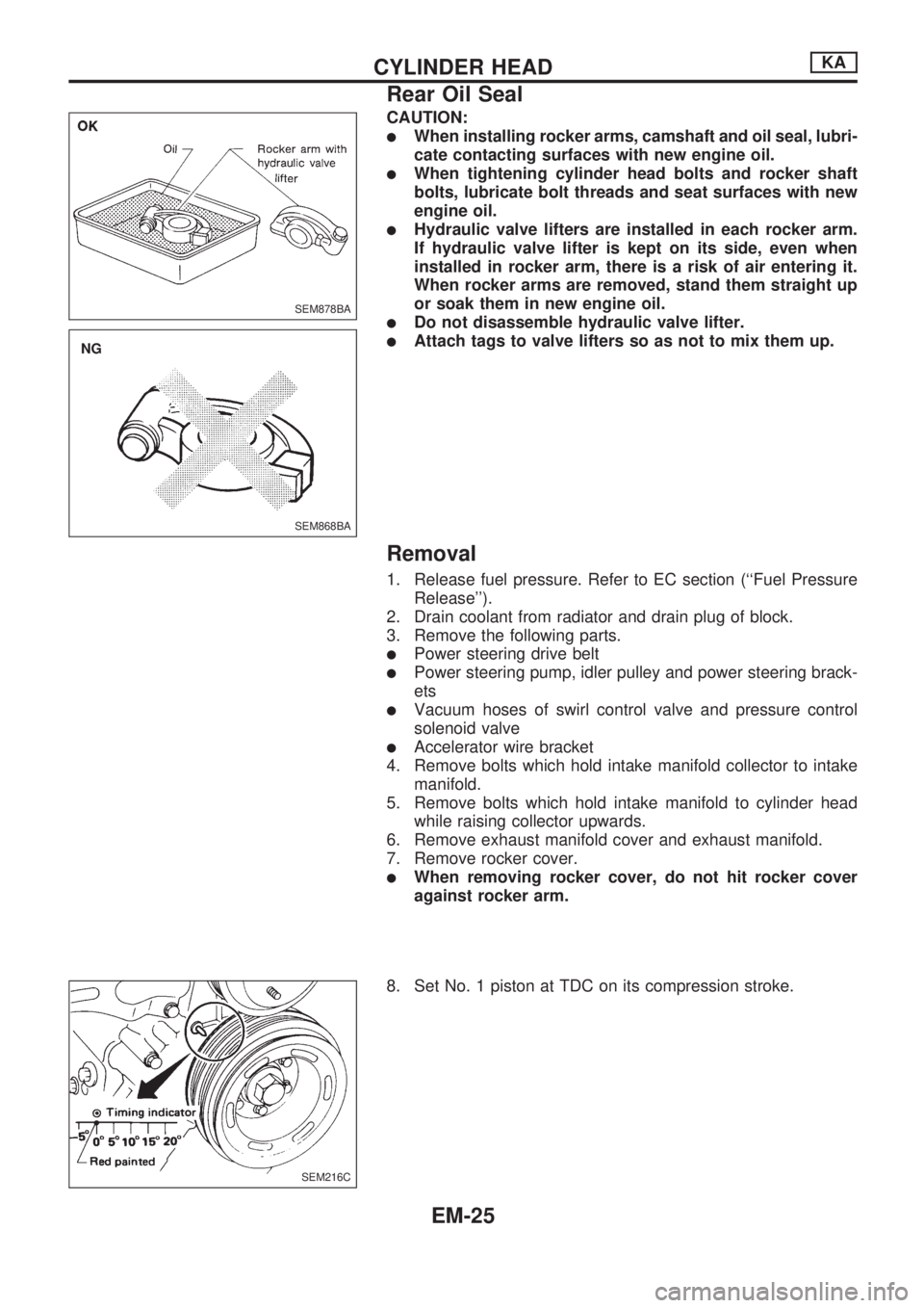
CAUTION:
lWhen installing rocker arms, camshaft and oil seal, lubri-
cate contacting surfaces with new engine oil.
lWhen tightening cylinder head bolts and rocker shaft
bolts, lubricate bolt threads and seat surfaces with new
engine oil.
lHydraulic valve lifters are installed in each rocker arm.
If hydraulic valve lifter is kept on its side, even when
installed in rocker arm, there is a risk of air entering it.
When rocker arms are removed, stand them straight up
or soak them in new engine oil.
lDo not disassemble hydraulic valve lifter.
lAttach tags to valve lifters so as not to mix them up.
Removal
1. Release fuel pressure. Refer to EC section (``Fuel Pressure
Release'').
2. Drain coolant from radiator and drain plug of block.
3. Remove the following parts.
lPower steering drive belt
lPower steering pump, idler pulley and power steering brack-
ets
lVacuum hoses of swirl control valve and pressure control
solenoid valve
lAccelerator wire bracket
4. Remove bolts which hold intake manifold collector to intake
manifold.
5. Remove bolts which hold intake manifold to cylinder head
while raising collector upwards.
6. Remove exhaust manifold cover and exhaust manifold.
7. Remove rocker cover.
lWhen removing rocker cover, do not hit rocker cover
against rocker arm.
8. Set No. 1 piston at TDC on its compression stroke.
SEM878BA
SEM868BA
.NG
SEM216C
CYLINDER HEADKA
Rear Oil Seal
EM-25
Page 681 of 1659
WARNING:
lPosition vehicle on a flat and solid surface.
lPlace chocks at front and back of rear wheels.
lDo not remove engine until exhaust system has com-
pletely cooled off.
Otherwise, you may burn yourself and/or fire may break
out in fuel line.
lBefore disconnecting fuel hose, release fuel pressure.
Refer to EC section (``Fuel Pressure Release'').
lBe sure to hoist engine and transmission in a safe man-
ner.
lFor engines not equipped with engine slingers, attach
proper slingers and bolts described in PARTS CATA-
LOG.
CAUTION:
lWhen lifting engine, be sure to clear surrounding parts.
Take special care near accelerator wire casing, brake
lines and brake master cylinder.
lIn lifting the engine, always use engine slingers in a safe
manner.
lFor 4WD models, apply sealant between engine and
transmission. Refer to MT section (``Removal and Instal-
lation'').
SEM601FA
ENGINE REMOVALKA
EM-36
Page 682 of 1659
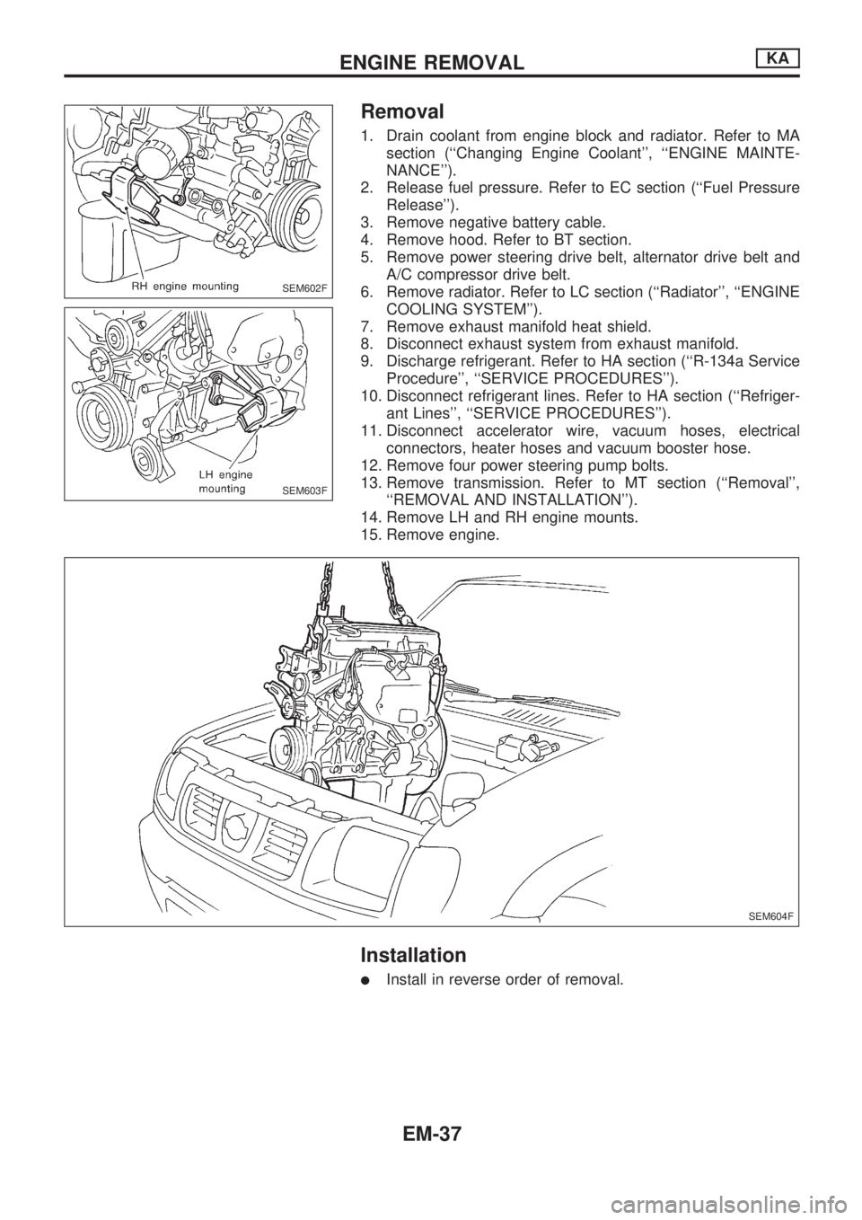
Removal
1. Drain coolant from engine block and radiator. Refer to MA
section (``Changing Engine Coolant'', ``ENGINE MAINTE-
NANCE'').
2. Release fuel pressure. Refer to EC section (``Fuel Pressure
Release'').
3. Remove negative battery cable.
4. Remove hood. Refer to BT section.
5. Remove power steering drive belt, alternator drive belt and
A/C compressor drive belt.
6. Remove radiator. Refer to LC section (``Radiator'', ``ENGINE
COOLING SYSTEM'').
7. Remove exhaust manifold heat shield.
8. Disconnect exhaust system from exhaust manifold.
9. Discharge refrigerant. Refer to HA section (``R-134a Service
Procedure'', ``SERVICE PROCEDURES'').
10. Disconnect refrigerant lines. Refer to HA section (``Refriger-
ant Lines'', ``SERVICE PROCEDURES'').
11. Disconnect accelerator wire, vacuum hoses, electrical
connectors, heater hoses and vacuum booster hose.
12. Remove four power steering pump bolts.
13. Remove transmission. Refer to MT section (``Removal'',
``REMOVAL AND INSTALLATION'').
14. Remove LH and RH engine mounts.
15. Remove engine.
Installation
lInstall in reverse order of removal.
SEM602F
SEM603F
SEM604F
ENGINE REMOVALKA
EM-37