1998 NISSAN PICK-UP fuel pressure
[x] Cancel search: fuel pressurePage 696 of 1659
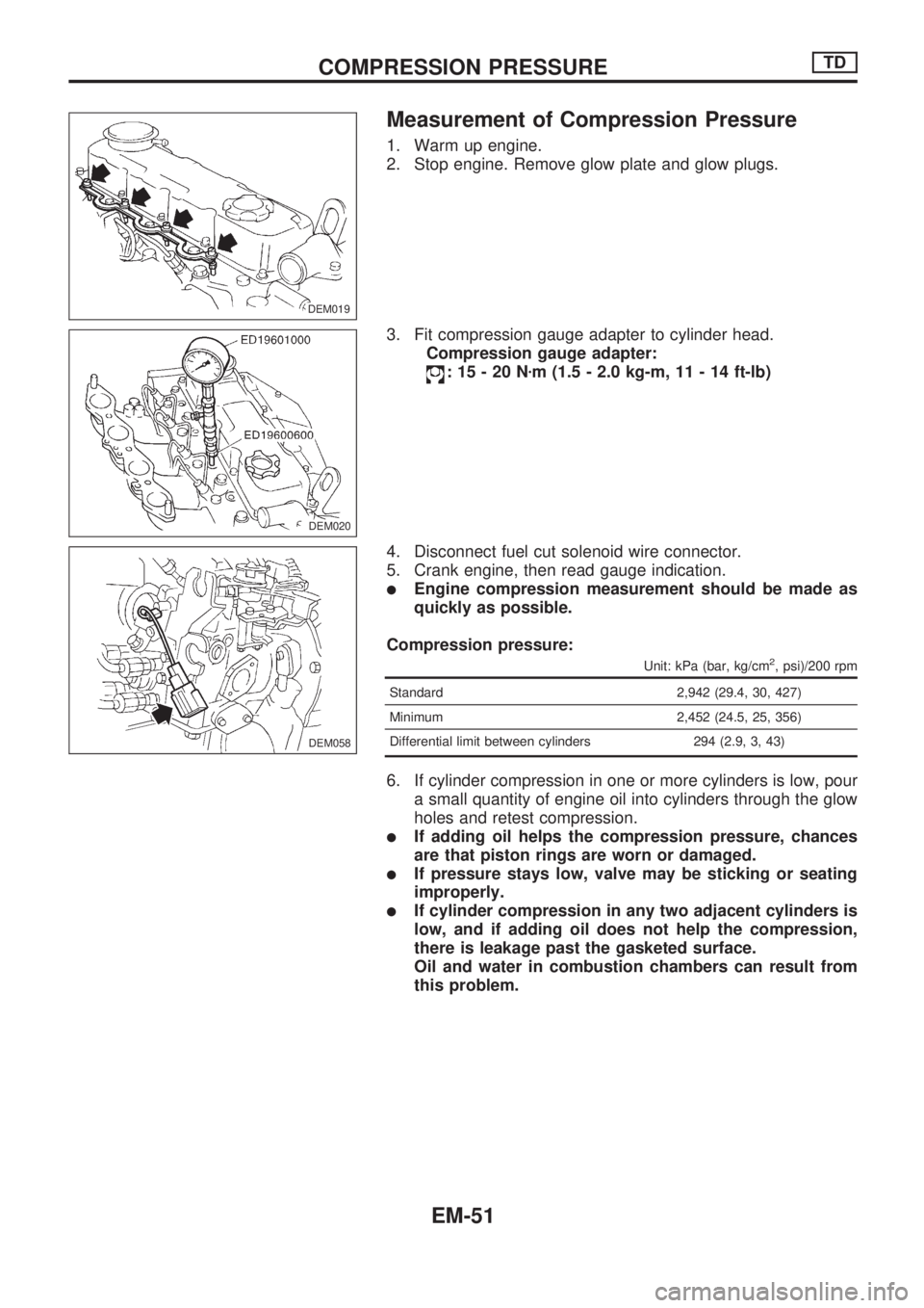
Measurement of Compression Pressure
1. Warm up engine.
2. Stop engine. Remove glow plate and glow plugs.
3. Fit compression gauge adapter to cylinder head.
Compression gauge adapter:
:15-20Nzm (1.5 - 2.0 kg-m, 11 - 14 ft-lb)
4. Disconnect fuel cut solenoid wire connector.
5. Crank engine, then read gauge indication.
lEngine compression measurement should be made as
quickly as possible.
Compression pressure:
Unit: kPa (bar, kg/cm2, psi)/200 rpm
Standard 2,942 (29.4, 30, 427)
Minimum 2,452 (24.5, 25, 356)
Differential limit between cylinders 294 (2.9, 3, 43)
6. If cylinder compression in one or more cylinders is low, pour
a small quantity of engine oil into cylinders through the glow
holes and retest compression.
lIf adding oil helps the compression pressure, chances
are that piston rings are worn or damaged.
lIf pressure stays low, valve may be sticking or seating
improperly.
lIf cylinder compression in any two adjacent cylinders is
low, and if adding oil does not help the compression,
there is leakage past the gasketed surface.
Oil and water in combustion chambers can result from
this problem.
DEM019.DEM019
DEM020
DEM058
COMPRESSION PRESSURETD
EM-51
Page 759 of 1659
WARNING:
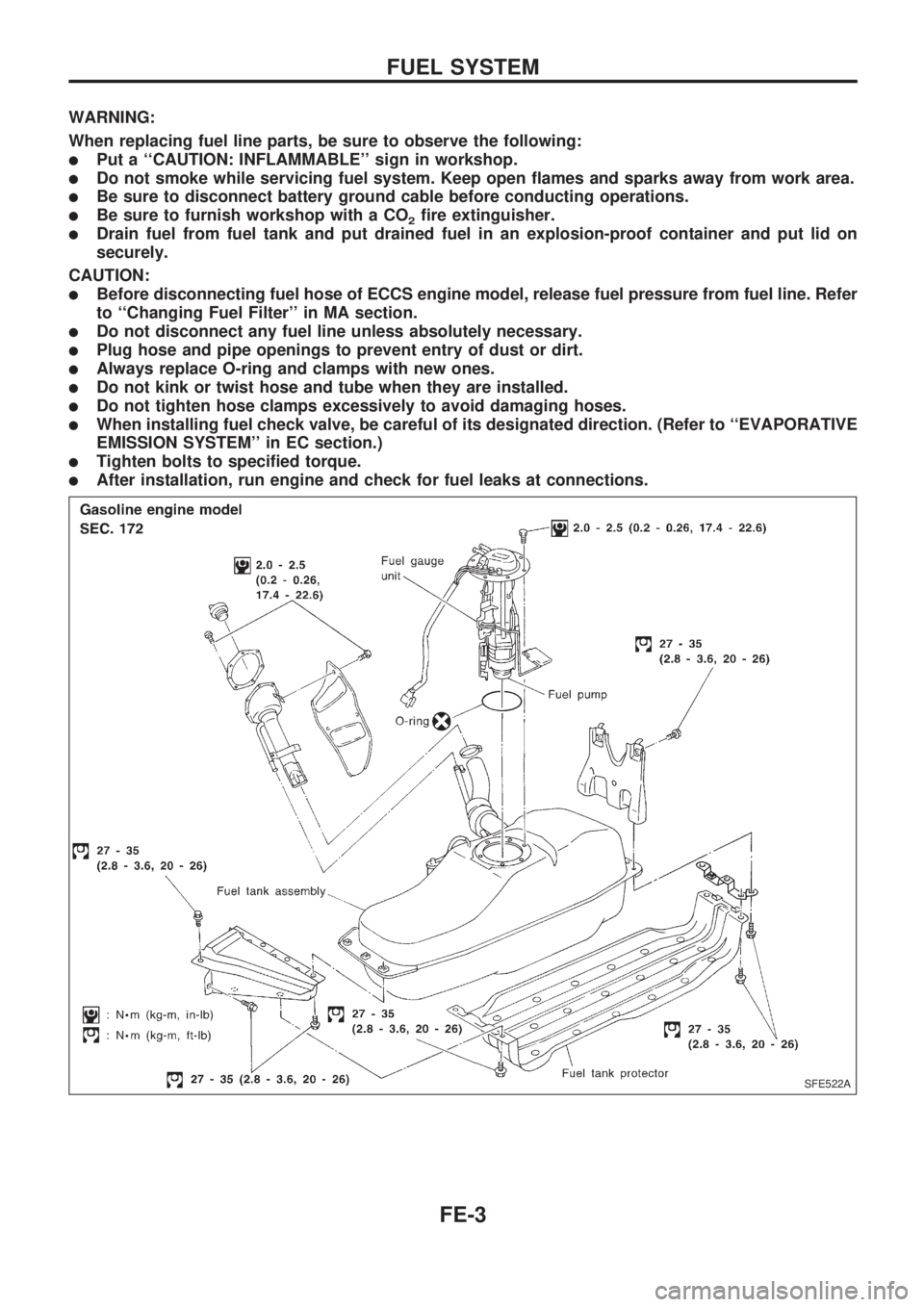
When replacing fuel line parts, be sure to observe the following:
lPut a ``CAUTION: INFLAMMABLE'' sign in workshop.
lDo not smoke while servicing fuel system. Keep open flames and sparks away from work area.
lBe sure to disconnect battery ground cable before conducting operations.
lBe sure to furnish workshop with a CO2fire extinguisher.
lDrain fuel from fuel tank and put drained fuel in an explosion-proof container and put lid on
securely.
CAUTION:
lBefore disconnecting fuel hose of ECCS engine model, release fuel pressure from fuel line. Refer
to ``Changing Fuel Filter'' in MA section.
lDo not disconnect any fuel line unless absolutely necessary.
lPlug hose and pipe openings to prevent entry of dust or dirt.
lAlways replace O-ring and clamps with new ones.
lDo not kink or twist hose and tube when they are installed.
lDo not tighten hose clamps excessively to avoid damaging hoses.
lWhen installing fuel check valve, be careful of its designated direction. (Refer to ``EVAPORATIVE
EMISSION SYSTEM'' in EC section.)
lTighten bolts to specified torque.
lAfter installation, run engine and check for fuel leaks at connections.
SFE522A
FUEL SYSTEM
FE-3
Page 808 of 1659
lAfter disconnecting vacuum or air hoses, attach a tag to
indicate the proper connection.
lUse only the fluids and lubricants specified in this manual.
lUse approved bonding agent, sealants or their equivalents
when required.
lUse tools and recommended special tools where specified
for safe and efficient service repairs.
lWhen repairing the fuel, oil, water, vacuum or exhaust
systems, check all affected lines for leaks.
lDispose of drained oil or the solvent used for cleaning parts
in an appropriate manner.
WARNING:
To prevent ECM from storing the diagnostic trouble codes,
do not carelessly disconnect the harness connectors which
are related to the ECCS system and TCM (Transmission
Control Module) system. The connectors should be discon-
nected only when working according to the WORK FLOW of
TROUBLE DIAGNOSES in EC section.
Precautions for Multiport Fuel Injection
System or ECCS Engine
lBefore connecting or disconnecting any harness connector
for the multiport fuel injection system or ECM (Engine Con-
trol Module):
Turn ignition switch to ``OFF'' position.
Disconnect negative battery terminal.
Otherwise, there may be damage to ECM.
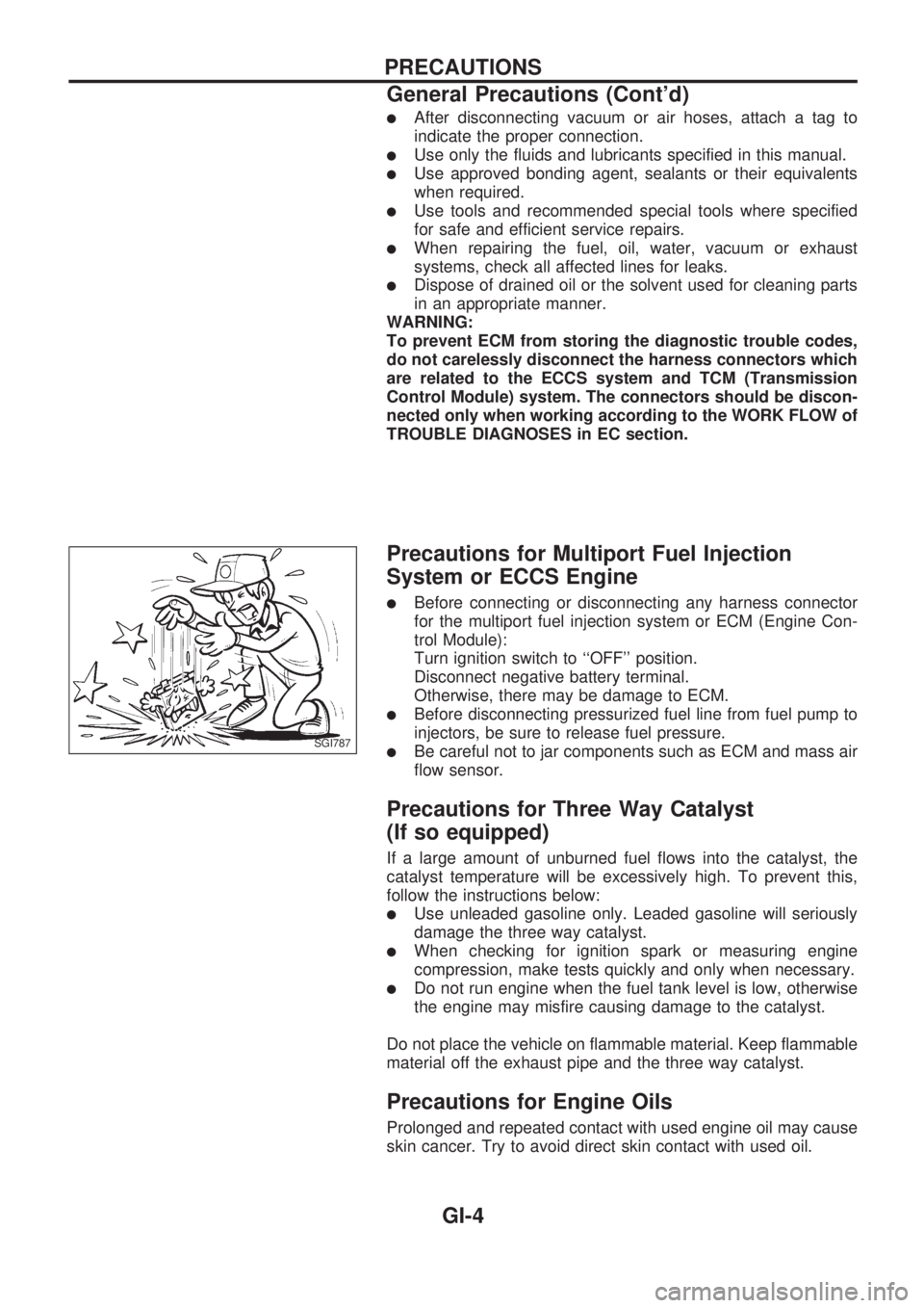
lBefore disconnecting pressurized fuel line from fuel pump to
injectors, be sure to release fuel pressure.
lBe careful not to jar components such as ECM and mass air
flow sensor.
Precautions for Three Way Catalyst
(If so equipped)
If a large amount of unburned fuel flows into the catalyst, the
catalyst temperature will be excessively high. To prevent this,
follow the instructions below:
lUse unleaded gasoline only. Leaded gasoline will seriously
damage the three way catalyst.
lWhen checking for ignition spark or measuring engine
compression, make tests quickly and only when necessary.
lDo not run engine when the fuel tank level is low, otherwise
the engine may misfire causing damage to the catalyst.
Do not place the vehicle on flammable material. Keep flammable
material off the exhaust pipe and the three way catalyst.
Precautions for Engine Oils
Prolonged and repeated contact with used engine oil may cause
skin cancer. Try to avoid direct skin contact with used oil.
SGI787
PRECAUTIONS
General Precautions (Cont'd)
GI-4
Page 859 of 1659
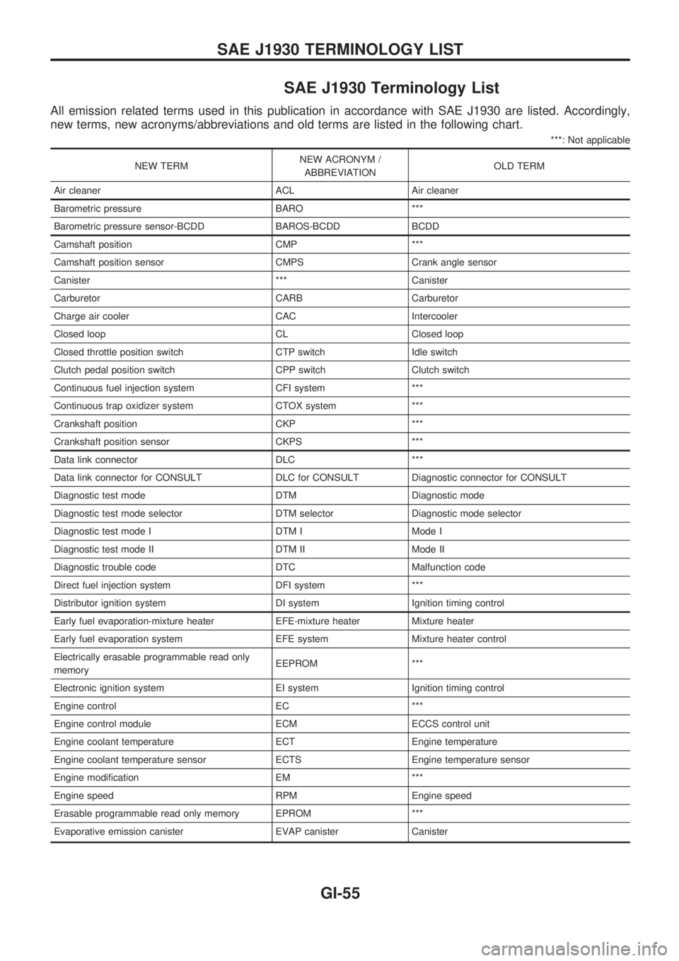
SAE J1930 Terminology List
All emission related terms used in this publication in accordance with SAE J1930 are listed. Accordingly,
new terms, new acronyms/abbreviations and old terms are listed in the following chart.
***: Not applicable
NEW TERMNEW ACRONYM /
ABBREVIATIONOLD TERM
Air cleaner ACL Air cleaner
Barometric pressure BARO ***
Barometric pressure sensor-BCDD BAROS-BCDD BCDD
Camshaft position CMP ***
Camshaft position sensor CMPS Crank angle sensor
Canister *** Canister
Carburetor CARB Carburetor
Charge air cooler CAC Intercooler
Closed loop CL Closed loop
Closed throttle position switch CTP switch Idle switch
Clutch pedal position switch CPP switch Clutch switch
Continuous fuel injection system CFI system ***
Continuous trap oxidizer system CTOX system ***
Crankshaft position CKP ***
Crankshaft position sensor CKPS ***
Data link connector DLC ***
Data link connector for CONSULT DLC for CONSULT Diagnostic connector for CONSULT
Diagnostic test mode DTM Diagnostic mode
Diagnostic test mode selector DTM selector Diagnostic mode selector
Diagnostic test mode I DTM I Mode I
Diagnostic test mode II DTM II Mode II
Diagnostic trouble code DTC Malfunction code
Direct fuel injection system DFI system ***
Distributor ignition system DI system Ignition timing control
Early fuel evaporation-mixture heater EFE-mixture heater Mixture heater
Early fuel evaporation system EFE system Mixture heater control
Electrically erasable programmable read only
memoryEEPROM ***
Electronic ignition system EI system Ignition timing control
Engine control EC ***
Engine control module ECM ECCS control unit
Engine coolant temperature ECT Engine temperature
Engine coolant temperature sensor ECTS Engine temperature sensor
Engine modification EM ***
Engine speed RPM Engine speed
Erasable programmable read only memory EPROM ***
Evaporative emission canister EVAP canister Canister
SAE J1930 TERMINOLOGY LIST
GI-55
Page 860 of 1659
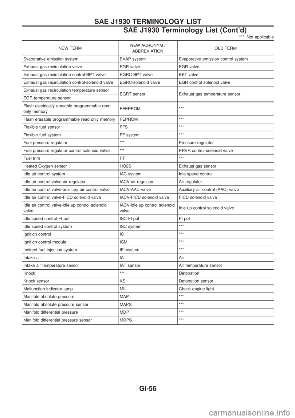
***: Not applicable
NEW TERMNEW ACRONYM /
ABBREVIATIONOLD TERM
Evaporative emission system EVAP system Evaporative emission control system
Exhaust gas recirculation valve EGR valve EGR valve
Exhaust gas recirculation control-BPT valve EGRC-BPT valve BPT valve
Exhaust gas recirculation control-solenoid valve EGRC-solenoid valve EGR control solenoid valve
Exhaust gas recirculation temperature sensor
EGRT sensor Exhaust gas temperature sensor
EGR temperature sensor
Flash electrically erasable programmable read
only memoryFEEPROM ***
Flash erasable programmable read only memory FEPROM ***
Flexible fuel sensor FFS ***
Flexible fuel system FF system ***
Fuel pressure regulator *** Pressure regulator
Fuel pressure regulator control solenoid valve *** PRVR control solenoid valve
Fuel trim FT ***
Heated Oxygen sensor HO2S Exhaust gas sensor
Idle air control system IAC system Idle speed control
Idle air control valve-air regulator IACV-air regulator Air regulator
Idle air control valve-auxiliary air control valve IACV-AAC valve Auxiliary air control (AAC) valve
Idle air control valve-FICD solenoid valve IACV-FICD solenoid valve FICD solenoid valve
Idle air control valve-idle up control solenoid
valveIACV-idle up control solenoid
valveIdle up control solenoid valve
Idle speed control-FI pot ISC-FI pot FI pot
Idle speed control system ISC system ***
Ignition control IC ***
Ignition control module ICM ***
Indirect fuel injection system IFI system ***
Intake air IA Air
Intake air temperature sensor IAT sensor Air temperature sensor
Knock *** Detonation
Knock sensor KS Detonation sensor
Malfunction indicator lamp MIL Check engine light
Manifold absolute pressure MAP ***
Manifold absolute pressure sensor MAPS ***
Manifold differential pressure MDP ***
Manifold differential pressure sensor MDPS ***
SAE J1930 TERMINOLOGY LIST
SAE J1930 Terminology List (Cont'd)
GI-56
Page 866 of 1659

EVAP vapor lines inspection ....................... MA-22
Electrical diagnoses ...................................... GI-21
Engine compartment .................................... BT-44
Engine control module (ECM) ....................... EC-5
Engine coolant temperature sensor
(ECTS) (KA24 engine) ............................. EC-95
Engine coolant temperature sensor
(ECTS) (TD25 engine) ........................... EC-209
Engine oil filter replacement
(KA24 engine).......................................... MA-20
Engine oil filter replacement
(TD25 engine).......................................... MA-24
Engine oil precautions .................................... GI-4
Engine oil replacement
(KA24 engine).......................................... MA-19
Engine oil replacement
(TD25 engine).......................................... MA-24
Engine outer component parts
(KA24 engine)............................................ EM-9
Engine outer component parts
(TD25 engine).......................................... EM-49
Engine removal (KA24 engine) ................... EM-36
Engine removal (TD25 engine) ................... EM-69
Engine room - See Engine
compartment............................................. BT-44
Engine speed sensor ................................. EC-219
Evaporative emission (EVAP) system ......... EC-19
Exhaust system inspection.......................... MA-32
Exhaust system .............................................. FE-5
Exterior ......................................................... BT-24
F
F/PUMP - Wiring diagram...........................EC-153
FCUT - Wiring diagram ............................. EC-225
FICD - Wiring diagram (KA24 engine) ...... EC-168
FICD - Wiring diagram (TD25 engine) ...... EC-230
Fan switch.................................................... HA-43
Fast idle cam (FIC) inspection and
adjustment................................................ EC-24
Final drive disassembly (C200) ................... PD-34
Final drive disassembly (H233B)................. PD-56
Final drive pre-inspection (C200) ................ PD-34
Final drive pre-inspection (H233B) .............. PD-56
Final drive removal and installation ............. PD-15
Floor trim ...................................................... BT-15
Flow charts.................................................... GI-31
Fluids ........................................................... MA-12
Flywheel (clutch) .......................................... CL-12
Flywheel runout (KA24 engine)................... EM-45
Flywheel runout (TD25 engine)................... EM-80
Fog lamp, rear .............................................. EL-72
Fork rod (M/T) (FS5R30A) .......................... MT-38
Fork rod (M/T) (FS5W71C) ......................... MT-17
Front axle ..................................................... FA-12
Front bumper.................................................. BT-5
Front case (Transfer) ..................................... TF-8
Front combination lamp removal and
installation................................................... BT-5Front disc brake ........................................... BR-21
Front door..................................................... BT-10
Front drive shaft (Transfer) ............................ TF-9
Front final drive disassembly (4WD) ........... PD-17
Front final drive pre-inspection (4WD) ........ PD-17
Front final drive removal and installa-
tion (4WD) ................................................ PD-14
Front seat belt................................................ RS-3
Front seat ..................................................... BT-30
Front suspension.......................................... FA-26
Front washer .............................................. EL-120
Front wiper ................................................. EL-120
Fuel check valve .......................................... EC-20
Fuel cut control (at no load & high
engine speed) (KA24 engine) .................. EC-18
Fuel cut control (at no load & high
engine speed) ........................................ EC-225
Fuel filter replacement (KA24 engine) ........ MA-18
Fuel filter replacement (TD25 engine) ........ MA-27
Fuel injector ............................................... EC-144
Fuel line inspection (KA24 engine) ............. MA-18
Fuel line inspection (TD25 engine) ............. MA-28
Fuel precautions ............................................. GI-5
Fuel pressure check .................................... EC-22
Fuel pressure release .................................. EC-22
Fuel pump .................................................. EC-151
Fuel pump relay ......................................... EC-156
Fuel system .................................................... FE-3
Fuel tank vacuum relief valve...................... EC-20
Fuse block.................................................. Foldout
Fuse.............................................................. EL-13
Fusible link ................................................... EL-13G
GLOW - Wiring diagram .............................EC-197
Garage jack and safety stand....................... GI-49
Gear components (M/T) (FS5R30A) ........... MT-36
Gear components (M/T) (FS5W71C) .......... MT-15
Glass ............................................................ BT-10
Glow plug ................................................... EC-208
Glow relay .................................................. EC-208
Grease ......................................................... MA-12
Ground clearance ......................................... GI-44
Ground distribution ....................................... EL-14
H
H/AIM - Wiring diagram .................................EL-64
H/LAMP - Wiring diagram ............................ EL-44
H02S - Wiring diagram .............................. EC-124
HFC134a (R134a) system precaution ........... HA-2
HFC134a (R134a) system service
procedure ................................................. HA-48
HFC134a (R134a) system service
tools............................................................ HA-8
HFC134a system service equipment
precaution ................................................ HA-10
ALPHABETICAL INDEX
IDX-4
Page 868 of 1659
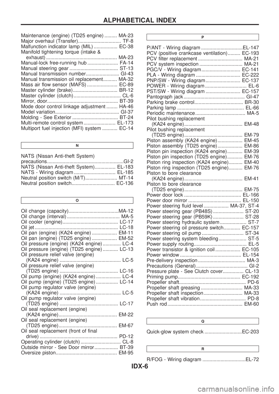
Maintenance (engine) (TD25 engine) ......... MA-23
Major overhaul (Transfer)............................... TF-8
Malfunction indicator lamp (MIL) ................. EC-38
Manifold tightening torque (intake &
exhaust) ................................................... MA-23
Manual-lock free-running hub ...................... FA-14
Manual steering gear ................................... ST-13
Manual transmission number........................ GI-43
Manual transmission oil replacement.......... MA-32
Mass air flow sensor (MAFS) ...................... EC-89
Master cylinder (brake) ................................ BR-12
Master cylinder (clutch) .................................. CL-6
Mirror, door................................................... BT-39
Mode door control linkage adjustment ........ HA-46
Model variation.............................................. GI-37
Molding - See Exterior ................................. BT-24
Multi-remote control system ....................... EL-173
Multiport fuel injection (MFI) system ........... EC-14
N
NATS (Nissan Anti-theft System)
precautions .......................................................GI-2
NATS (Nissan Anti-theft System)............... EL-183
NATS - Wiring diagram .............................. EL-185
Neutral position switch (M/T)....................... MT-14
Neutral position switch............................... EC-136
O
Oil change (capacity)....................................MA-12
Oil change (interval) ...................................... MA-5
Oil cooler (engine)........................................ LC-17
Oil jet ............................................................ LC-18
Oil pan (engine) (KA24 engine) .................. EM-11
Oil pan (engine) (TD25 engine) .................. EM-52
Oil pressure (engine) (KA24 engine) ............. LC-4
Oil pressure (engine) (TD25 engine) ........... LC-13
Oil pressure relief valve (engine)
(KA24 engine) ............................................ LC-5
Oil pressure relief valve (engine)
(TD25 engine) .......................................... LC-16
Oil pump (engine) (KA24 engine) .................. LC-4
Oil pump (engine) (TD25 engine) ................ LC-14
Oil pump regulator valve (engine)
(KA24 engine) ............................................ LC-5
Oil pump regulator valve (engine)
(TD25 engine) .......................................... LC-17
Oil seal replacement (engine)
(KA24 engine).......................................... EM-22
Oil seal replacement (engine)
(TD25 engine).......................................... EM-67
Oil seal replacement (front of final
drive) ........................................................ PD-12
Operating cylinder (clutch) ............................. CL-8
Outside mirror - See Door mirror ................. BT-39
Oversize piston............................................ EM-95
P
P/ANT - Wiring diagram ..............................EL-147
PCV (positive crankcase ventilation) ......... EC-193
PCV filter replacement ................................ MA-21
PCV system inspection ............................... MA-21
PGC/V - Wiring diagram ............................ EC-141
PLA - Wiring diagram ................................ EC-222
PNP/SW - Wiring diagram ......................... EC-137
POWER - Wiring diagram .............................. EL-6
PST/SW - Wiring diagram ......................... EC-157
Pantograph jack ............................................ GI-47
Parking brake control................................... BR-30
Parking lamp ................................................ EL-66
Periodic maintenance .................................... MA-5
Pilot bushing replacement
(KA24 engine).......................................... EM-48
Pilot bushing replacement
(TD25 engine).......................................... EM-79
Piston assembly (KA24 engine) .................. EM-45
Piston assembly (TD25 engine) .................. EM-86
Piston pin inspection (KA24 engine) ........... EM-39
Piston pin inspection (TD25 engine) ........... EM-76
Piston ring inspection (KA24 engine).......... EM-40
Piston ring inspection (TD25 engine).......... EM-76
Piston to bore clearance
(KA24 engine).......................................... EM-41
Piston to bore clearance
(TD25 engine).......................................... EM-75
Power door lock ......................................... EL-166
Power door mirror ...................................... EL-150
Power steering fluid level .................. MA-37, ST-4
Power steering gear (PB48S) ...................... ST-20
Power steering gear (PB59K) ...................... ST-28
Power steering hydraulic system ................... ST-7
Power steering oil pressure switch............ EC-157
Power steering oil pump .............................. ST-34
Power steering system bleeding .................... ST-5
Power supply routing...................................... EL-5
Power transistor & ignition coil .................. EC-105
Power window ............................................ EL-154
Pre-delivery inspection .................................. MA-3
Precautions (General) ..................................... GI-2
Pressure plate - See Clutch cover............... CL-13
Priming pump............................................. EC-192
Propeller shaft................................................ PD-6
Propeller shaft greasing .............................. MA-33
Propeller shaft inspection ............................ MA-33
Propeller shaft vibration ................................. PD-8
Push rod ...................................................... EM-60
Q
Quick-glow system check ...........................EC-203
R
R/FOG - Wiring diagram ...............................EL-72
ALPHABETICAL INDEX
IDX-6
Page 976 of 1659
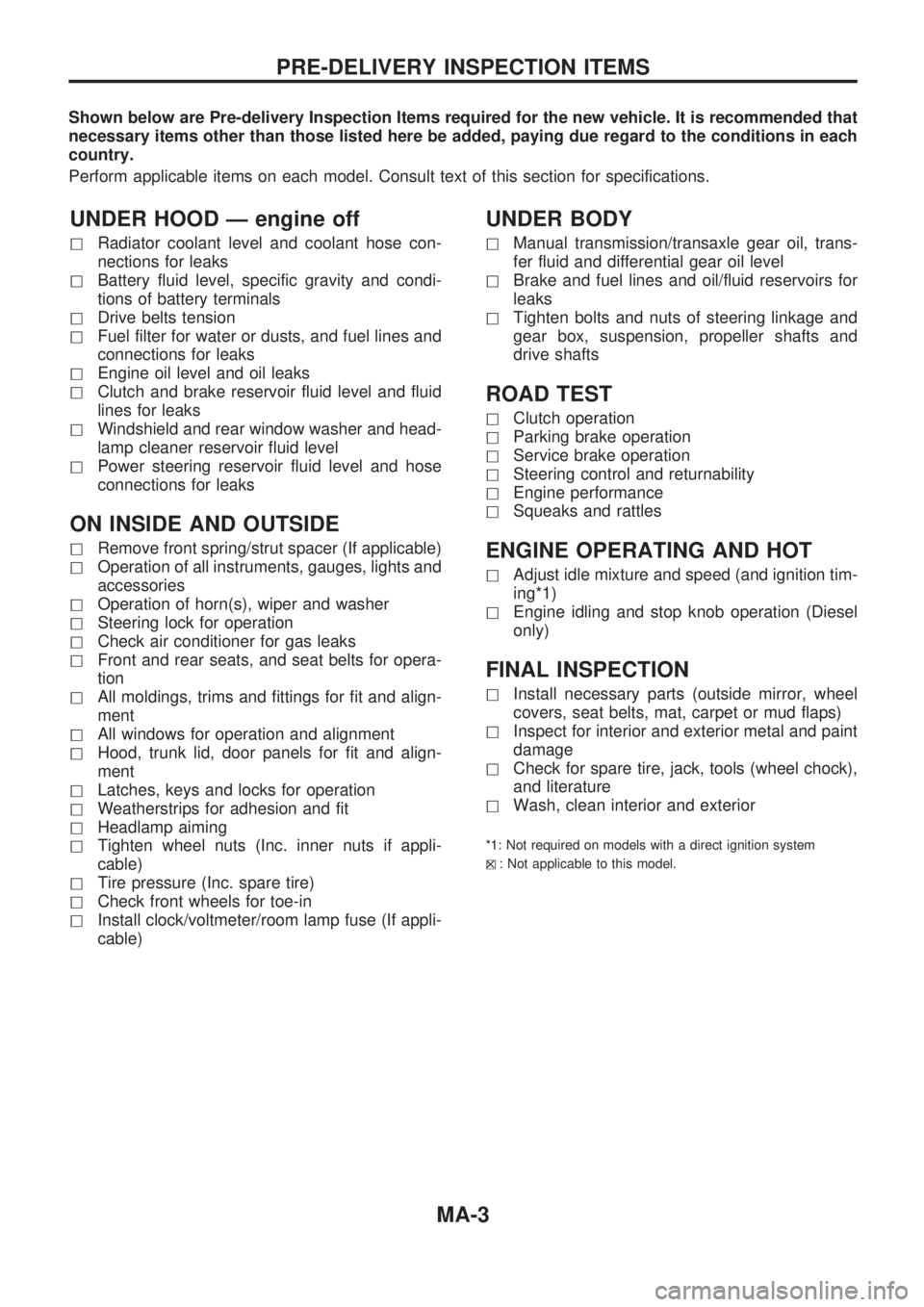
Shown below are Pre-delivery Inspection Items required for the new vehicle. It is recommended that
necessary items other than those listed here be added, paying due regard to the conditions in each
country.
Perform applicable items on each model. Consult text of this section for specifications.
UNDER HOOD Ð engine off
hRadiator coolant level and coolant hose con-
nections for leaks
hBattery fluid level, specific gravity and condi-
tions of battery terminals
hDrive belts tension
hFuel filter for water or dusts, and fuel lines and
connections for leaks
hEngine oil level and oil leaks
hClutch and brake reservoir fluid level and fluid
lines for leaks
hWindshield and rear window washer and head-
lamp cleaner reservoir fluid level
hPower steering reservoir fluid level and hose
connections for leaks
ON INSIDE AND OUTSIDE
hRemove front spring/strut spacer (If applicable)
hOperation of all instruments, gauges, lights and
accessories
hOperation of horn(s), wiper and washer
hSteering lock for operation
hCheck air conditioner for gas leaks
hFront and rear seats, and seat belts for opera-
tion
hAll moldings, trims and fittings for fit and align-
ment
hAll windows for operation and alignment
hHood, trunk lid, door panels for fit and align-
ment
hLatches, keys and locks for operation
hWeatherstrips for adhesion and fit
hHeadlamp aiming
hTighten wheel nuts (Inc. inner nuts if appli-
cable)
hTire pressure (Inc. spare tire)
hCheck front wheels for toe-in
hInstall clock/voltmeter/room lamp fuse (If appli-
cable)
UNDER BODY
hManual transmission/transaxle gear oil, trans-
fer fluid and differential gear oil level
hBrake and fuel lines and oil/fluid reservoirs for
leaks
hTighten bolts and nuts of steering linkage and
gear box, suspension, propeller shafts and
drive shafts
ROAD TEST
hClutch operation
hParking brake operation
hService brake operation
hSteering control and returnability
hEngine performance
hSqueaks and rattles
ENGINE OPERATING AND HOT
hAdjust idle mixture and speed (and ignition tim-
ing*1)
hEngine idling and stop knob operation (Diesel
only)
FINAL INSPECTION
hInstall necessary parts (outside mirror, wheel
covers, seat belts, mat, carpet or mud flaps)
hInspect for interior and exterior metal and paint
damage
hCheck for spare tire, jack, tools (wheel chock),
and literature
hWash, clean interior and exterior
*1: Not required on models with a direct ignition system
h
X: Not applicable to this model.
PRE-DELIVERY INSPECTION ITEMS
MA-3