Page 214 of 1659

Symptom Matrix Chart
SYMPTOM
Reference page
HARD/NO START/RESTART (EXCP. HA)
ENGINE STALL
HESITATION/SURGING/FLAT SPOT
SPARK KNOCK/DETONATION
LACK OF POWER/POOR ACCELERATION
HIGH IDLE/LOW IDLE
ROUGH IDLE/HUNTING
IDLING VIBRATION
SLOW/NO RETURN TO IDLE
OVERHEATS/WATER TEMPERATURE HIGH
EXCESSIVE FUEL CONSUMPTION
EXCESSIVE OIL CONSUMPTION
BATTERY DEAD (UNDER CHARGE)
OVERCOOLS
OVERCHARGING
Warranty Symptom Code AA AB AC AD AE AF AG AH AJ AK AL AM HA 1P 1X
Basic engine control system
Fuel Fuel pump circuitllljlljjjEC-151
Fuel pressure regulator system
llljljlljlEC-22
Injector circuit
llljlll lEC-144
Evaporative emission systemjjjj
ljjjj jEC-19
Air Positive crankcase ventilation systemjjjj
ljjjj jjEC-21
Incorrect idle speed adjustmentjj jjjj jEC-25
Swirl control valve circuitjj
lEC-161
IACV-AAC valve circuit
llljllllljjEC-131
IACV-FICD solenoid valve circuitjjjjjjjjj jEC-168
Ignition Incorrect ignition timing adjustmentjj
lll ll lEC-25
Ignition circuit
lllll ll lEC-99
EVAP EVAP canister purge control solenoid
valve circuit
ljjjj j jEC-140
Main power supply and ground circuit
llljj jj jj jEC-75
Air conditioner circuitjjjjjjjjj j jHA section
ECCS system
ECCS Camshaft position sensor circuitllllljj jEC-82
Mass air flow sensor circuit
lllll ljjEC-89
Heated oxygen sensor circuit
lljlljlEC-123, 127
Engine coolant temperature sensor circuit
llljllljjlEC-95
Throttle position sensor circuit
ll lllll lEC-113
Incorrect throttle position sensor adjust-
ment
ljjljjljEC-58
Vehicle speed sensor circuitjj j jEC-118
ECMjjjjjjjjjjjEC-61
Start signal circuitjEC-149
Neutral position switch circuitjjjj jEC-136
Power steering oil pressure switch circuitjjjEC-157
l; High Possibility Item
j; Low Possibility Item(continued on next page)
TROUBLE DIAGNOSIS Ð General DescriptionKA
EC-62
Page 307 of 1659

DIAGNOSTIC PROCEDURE
INSPECTION START
CHECK OVERALL FUNCTION.
1. Turn ignition switch ``ON''.
2. Pinch fuel feed hose with fingers.
Fuel pressure pulsation should be
felt on the fuel feed hose for 5 sec-
onds after ignition switch is turned
``ON''.
NG
cOK
INSPECTION END
CHECK POWER SUPPLY.
1. Turn ignition switch ``OFF''.
2. Disconnect fuel pump relay.
3. Turn ignition switch ``ON''.
4. Check voltage between terminals
V1,
V3and ground with CONSULT or
tester.
Voltage: Battery voltage
OK
cNG
Check the following.
l15A fuse
lHarness connectorsE101,M5
lHarness for open or
short between fuse and
fuel pump relay
If NG, repair harness or
connectors.
CHECK GROUND CIRCUIT.
1. Turn ignition switch ``OFF''.
2. Disconnect fuel pump harness connec-
tor.
3. Check harness continuity between ter-
minal
V6and body ground, relay ter-
minal
V5and terminalV5.
Continuity should exist.
If OK, check harness for short to
ground and short to power.
OK
cNG
Check the following.
lHarness connectorsC9,M121(LHD mod-
els for Europe)
lHarness connectorsE101,M5
lHarness for open or
short between fuel pump
and body ground
lHarness for open or
short between fuel pump
and fuel pump relay
If NG, repair open circuit,
short to ground or short to
power in harness or con-
nectors.
CHECK OUTPUT SIGNAL CIRCUIT.
1. Disconnect ECM harness connector.
2. Check harness continuity between
ECM terminal
104and terminalV2.
Continuity should exist.
If OK, check harness for short to
ground and short to power.
OK
cNG
Check the following.
lHarness connectorsE101,M5
lHarness connectorsM48,F54(RHD mod-
els)
lHarness for open or
short between ECM and
fuel pump relay
If NG, repair open circuit,
short to ground or short to
power in harness or con-
nectors.
VA
(Go to next page.)
SEF109U
SEF110U
SEF479P
SEF154U
.
.
.
.
.
TROUBLE DIAGNOSIS FOR NON-DETECTABLE ITEMSKA
Fuel Pump (Cont'd)
EC-155
Page 341 of 1659
Assembly
Assemble in the reverse order of disassembly.
Inlet connector to nozzle holder:
:29-49Nzm (3.0 - 5.0 kg-m, 22 - 36 ft-lb)
Test and Adjustment
WARNING:
When using nozzle tester, be careful not to allow diesel fuel
sprayed from nozzle to contact your hand or body, and
make sure your eyes are properly protected with goggles.
INJECTION PRESSURE TEST
1. Install nozzle to injection nozzle tester and bleed air from
flare nut.
2. Pump the tester handle slowly (one time per second) and
watch the pressure gauge.
3. Read the pressure gauge when the injection pressure just
starts dropping.
Initial injection pressure:
Used 9,807 - 10,297 kPa
(98.1 - 103.0 bar, 100 - 105 kg/cm
2,
1,422 - 1,493 psi)
New 10,297 - 11,278 kPa
(103.0 - 112.8 bar, 105 - 115 kg/cm
2,
1,493 - 1,635 psi)
Always check initial injection pressure using a new nozzle.
SEF967
EF791A
SEF672A
INJECTION NOZZLETD
EC-189
Page 372 of 1659
Description
To improve startability, a solenoid timer is used on models for
cold areas. Its purpose is to advance fuel injection timing in
relation to coolant temperature for a certain period after starting
the engine.
This timer is controlled by the signal from the glow control unit
(or ECM). The control unit sends a signal to activate the advance
mechanism of the fuel injection pump during cold starting.
Refer to ``Circuit Diagram'', ``QUICK-GLOW SYSTEM'', EC-195.
Operation
Part of the fuel in the return line returns to the fuel injection pump
inlet, when the solenoid timer is OFF. When cold starting, the
solenoid timer comes ON to stop the return of fuel to the inlet.
This increases the fuel pressure in the fuel injection pump so that
fuel injection timing advances. The duration of fuel injection tim-
ing advance varies with changes in coolant temperature.
SEF419FB
SEF914H
SOLENOID TIMERTD
EC-220
Page 378 of 1659
Description
This system prevents fuel filter from clogging with fuel wax.
Fuel heater system operates when fuel temperature switch and
oil pressure switch are on.
Fuel temperature switch turns on when fuel temperature
decreases below þ15ÉC (5ÉF). It remains on until fuel tempera-
ture increases to around 0ÉC (32ÉF).
If fuel temperature does not decrease below þ15ÉC (5ÉF), fuel
temperature switch will not turn on even though fuel temperature
is below 0ÉC (32ÉF).
DEC035
SEF541D
SEF411FA
FUEL HEATER SYSTEMTD
EC-226
Page 381 of 1659
When installing, use a new O-ring.
WARNING:
Do not touch the cooled fuel temperature switch with your
bare hand.
Oil pressure switch
1. Run engine at about 1,000 rpm.
2. Check continuity for oil pressure switch.
3. If oil pressure switch has malfunction, replace it.
Fuel heater relay
1. Check fuel heater relay operation.
2. If fuel heater relay does not operate, replace it.
SEF414F
SEF415F
DEC039
.)
.DEC039
FUEL HEATER SYSTEMTD
Component Inspection (Cont'd)
EC-229
Page 384 of 1659

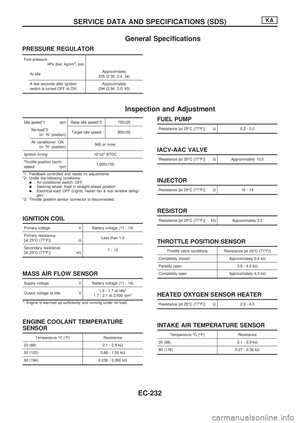
General Specifications
PRESSURE REGULATOR
Fuel pressure
kPa (bar, kg/cm2, psi)
At idleApproximately
235 (2.35, 2.4, 34)
A few seconds after ignition
switch is turned OFF to ONApproximately
294 (2.94, 3.0, 43)
Inspection and Adjustment
Idle speed*1 rpm Base idle speed*3 750 25
No-load*2
(in ``N'' position)Target idle speed 800 50
Air conditioner: ON
(in ``N'' position)900 or more
Ignition timing 10É 2É BTDC
Throttle position touch
speed rpm1,000 150
*1: Feedback controlled and needs no adjustments
*2: Under the following conditions:
lAir conditioner switch: OFFlSteering wheel: Kept in straight-ahead positionlElectrical load: OFF (Lights, heater fan & rear window defog-
ger)
*3: Throttle position sensor connector is disconnected.
IGNITION COIL
Primary voltage V Battery voltage (11 - 14)
Primary resistance
[at 25ÉC (77ÉF)]WLess than 1.0
Secondary resistance
[at 25ÉC (77ÉF)] kW7-13
MASS AIR FLOW SENSOR
Supply voltage V Battery voltage (11 - 14)
Output voltage at idle V1.3 - 1.7 at idle*
1.7 - 2.1 at 2,500 rpm*
*: Engine is warmed up sufficiently and running under no-load.
ENGINE COOLANT TEMPERATURE
SENSOR
Temperature ÉC (ÉF) Resistance
20 (68) 2.1 - 2.9 kW
50 (122) 0.68 - 1.00 kW
90 (194) 0.236 - 0.260 kW
FUEL PUMP
Resistance [at 25ÉC (77ÉF)]W0.2 - 5.0
IACV-AAC VALVE
Resistance [at 25ÉC (77ÉF)]WApproximately 10.0
INJECTOR
Resistance [at 25ÉC (77ÉF)]W10-14
RESISTOR
Resistance [at 25ÉC (77ÉF)] kWApproximately 2.2
THROTTLE POSITION SENSOR
Throttle valve conditions Resistance [at 25ÉC (77ÉF)]
Completely closed Approximately 0.6 kW
Partially open 0.6 - 4.0 kW
Completely open Approximately 4.0 kW
HEATED OXYGEN SENSOR HEATER
Resistance [at 25ÉC (77ÉF)]W2.3 - 4.3
INTAKE AIR TEMPERATURE SENSOR
Temperature ÉC (ÉF) Resistance
20 (68) 2.1 - 2.9 kW
80 (176) 0.27 - 0.38 kW
SERVICE DATA AND SPECIFICATIONS (SDS)KA
EC-232
Page 386 of 1659

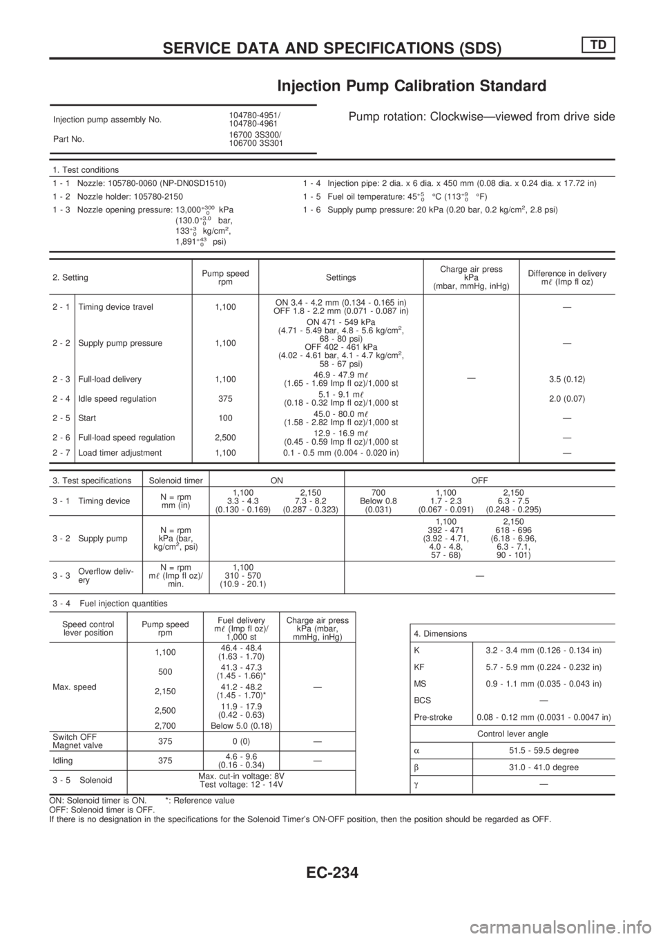
Injection Pump Calibration Standard
Injection pump assembly No.104780-4951/
104780-4961
Part No.16700 3S300/
106700 3S301Pump rotation: ClockwiseÐviewed from drive side
1. Test conditions
1 - 1 Nozzle: 105780-0060 (NP-DN0SD1510) 1 - 4 Injection pipe: 2 dia. x 6 dia. x 450 mm (0.08 dia. x 0.24 dia. x 17.72 in)
1 - 2 Nozzle holder: 105780-2150 1 - 5 Fuel oil temperature: 45
+5
0ÉC (113+9
0ÉF)
1 - 3 Nozzle opening pressure: 13,000+300
0kPa
(130.0+3.0
0bar,
133+3
0kg/cm2,
1,891+43
0psi)1 - 6 Supply pump pressure: 20 kPa (0.20 bar, 0.2 kg/cm
2, 2.8 psi)
2. SettingPump speed
rpmSettingsCharge air press
kPa
(mbar, mmHg, inHg)Difference in delivery
m!(Imp fl oz)
2 - 1 Timing device travel 1,100ON 3.4 - 4.2 mm (0.134 - 0.165 in)
OFF 1.8 - 2.2 mm (0.071 - 0.087 in)
ÐÐ
2 - 2 Supply pump pressure 1,100ON 471 - 549 kPa
(4.71 - 5.49 bar, 4.8 - 5.6 kg/cm
2,
68 - 80 psi)
OFF 402 - 461 kPa
(4.02 - 4.61 bar, 4.1 - 4.7 kg/cm
2,
58 - 67 psi)Ð
2 - 3 Full-load delivery 1,10046.9 - 47.9 m!
(1.65 - 1.69 Imp fl oz)/1,000 st3.5 (0.12)
2 - 4 Idle speed regulation 3755.1 - 9.1 m!
(0.18 - 0.32 Imp fl oz)/1,000 st2.0 (0.07)
2 - 5 Start 10045.0 - 80.0 m!
(1.58 - 2.82 Imp fl oz)/1,000 stÐ
2 - 6 Full-load speed regulation 2,50012.9 - 16.9 m!
(0.45 - 0.59 Imp fl oz)/1,000 stÐ
2 - 7 Load timer adjustment 1,100 0.1 - 0.5 mm (0.004 - 0.020 in) Ð
3. Test specifications Solenoid timer ON OFF
3 - 1 Timing deviceN = rpm
mm (in)1,100
3.3 - 4.3
(0.130 - 0.169)2,150
7.3 - 8.2
(0.287 - 0.323)700
Below 0.8
(0.031)1,100
1.7 - 2.3
(0.067 - 0.091)2,150
6.3 - 7.5
(0.248 - 0.295)
3 - 2 Supply pumpN = rpm
kPa (bar,
kg/cm
2, psi)1,100
392 - 471
(3.92 - 4.71,
4.0 - 4.8,
57 - 68)2,150
618 - 696
(6.18 - 6.96,
6.3 - 7.1,
90 - 101)
3-3Overflow deliv-
eryN = rpm
m!(Imp fl oz)/
min.1,100
310 - 570
(10.9 - 20.1)Ð
3 - 4 Fuel injection quantities
Speed control
lever positionPump speed
rpmFuel delivery
m!(Imp fl oz)/
1,000 stCharge air press
kPa (mbar,
mmHg, inHg)
Max. speed1,10046.4 - 48.4
(1.63 - 1.70)
Ð 50041.3 - 47.3
(1.45 - 1.66)*
2,15041.2 - 48.2
(1.45 - 1.70)*
2,50011.9 - 17.9
(0.42 - 0.63)
2,700 Below 5.0 (0.18)
Switch OFF
Magnet valve375 0 (0) Ð
Idling 3754.6 - 9.6
(0.16 - 0.34)Ð
3 - 5 SolenoidMax. cut-in voltage: 8V
Test voltage: 12 - 14V
ON: Solenoid timer is ON. *: Reference value
OFF: Solenoid timer is OFF.
If there is no designation in the specifications for the Solenoid Timer's ON-OFF position, then the position should be regarded as OFF.
4. Dimensions
K 3.2 - 3.4 mm (0.126 - 0.134 in)
KF 5.7 - 5.9 mm (0.224 - 0.232 in)
MS 0.9 - 1.1 mm (0.035 - 0.043 in)
BCS Ð
Pre-stroke 0.08 - 0.12 mm (0.0031 - 0.0047 in)
Control lever angle
a51.5 - 59.5 degree
b31.0 - 41.0 degree
gÐ
SERVICE DATA AND SPECIFICATIONS (SDS)TD
EC-234