1998 NISSAN PICK-UP fuel pressure
[x] Cancel search: fuel pressurePage 175 of 1659
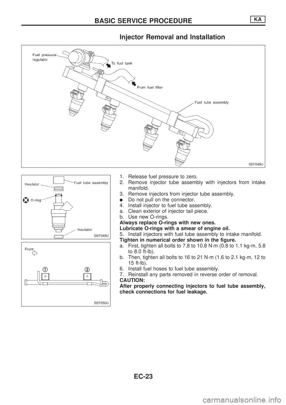
Injector Removal and Installation
1. Release fuel pressure to zero.
2. Remove injector tube assembly with injectors from intake
manifold.
3. Remove injectors from injector tube assembly.
lDo not pull on the connector.
4. Install injector to fuel tube assembly.
a. Clean exterior of injector tail piece.
b. Use new O-rings.
Always replace O-rings with new ones.
Lubricate O-rings with a smear of engine oil.
5. Install injectors with fuel tube assembly to intake manifold.
Tighten in numerical order shown in the figure.
a. First, tighten all bolts to 7.8 to 10.8 N´m (0.8 to 1.1 kg-m, 5.8
to 8.0 ft-lb).
b. Then, tighten all bolts to 16 to 21 N´m (1.6 to 2.1 kg-m, 12 to
15 ft-lb).
6. Install fuel hoses to fuel tube assembly.
7. Reinstall any parts removed in reverse order of removal.
CAUTION:
After properly connecting injectors to fuel tube assembly,
check connections for fuel leakage.
SEF048U
SEF049U
SEF050U
BASIC SERVICE PROCEDUREKA
EC-23
Page 177 of 1659
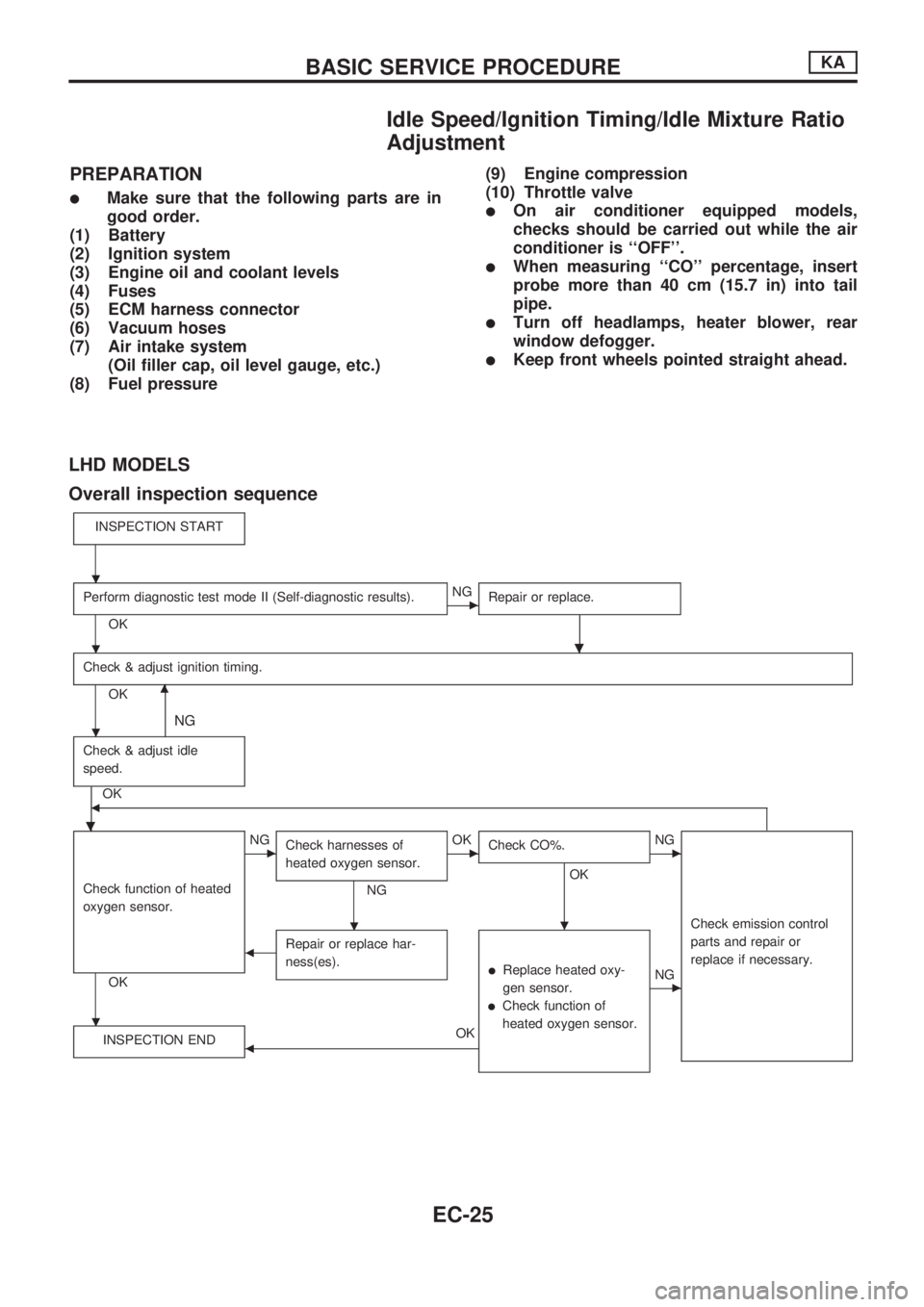
Idle Speed/Ignition Timing/Idle Mixture Ratio
Adjustment
PREPARATION
lMake sure that the following parts are in
good order.
(1) Battery
(2) Ignition system
(3) Engine oil and coolant levels
(4) Fuses
(5) ECM harness connector
(6) Vacuum hoses
(7) Air intake system
(Oil filler cap, oil level gauge, etc.)
(8) Fuel pressure(9) Engine compression
(10) Throttle valvelOn air conditioner equipped models,
checks should be carried out while the air
conditioner is ``OFF''.
lWhen measuring ``CO'' percentage, insert
probe more than 40 cm (15.7 in) into tail
pipe.
lTurn off headlamps, heater blower, rear
window defogger.
lKeep front wheels pointed straight ahead.
LHD MODELS
Overall inspection sequence
INSPECTION START
Perform diagnostic test mode II (Self-diagnostic results).
OK
cNG
Repair or replace.
.
Check & adjust ignition timing.
OKm
NG
Check & adjust idle
speed.
.
OKb
Check function of heated
oxygen sensor.
OK
cNG
Check harnesses of
heated oxygen sensor.
NG
cOK
Check CO%.
OK
.
cNG
Check emission control
parts and repair or
replace if necessary.
bRepair or replace har-
ness(es).
lReplace heated oxy-
gen sensor.
lCheck function of
heated oxygen sensor.
cNG
INSPECTION END
bOK
.
.
.
.
.
BASIC SERVICE PROCEDUREKA
EC-25
Page 182 of 1659
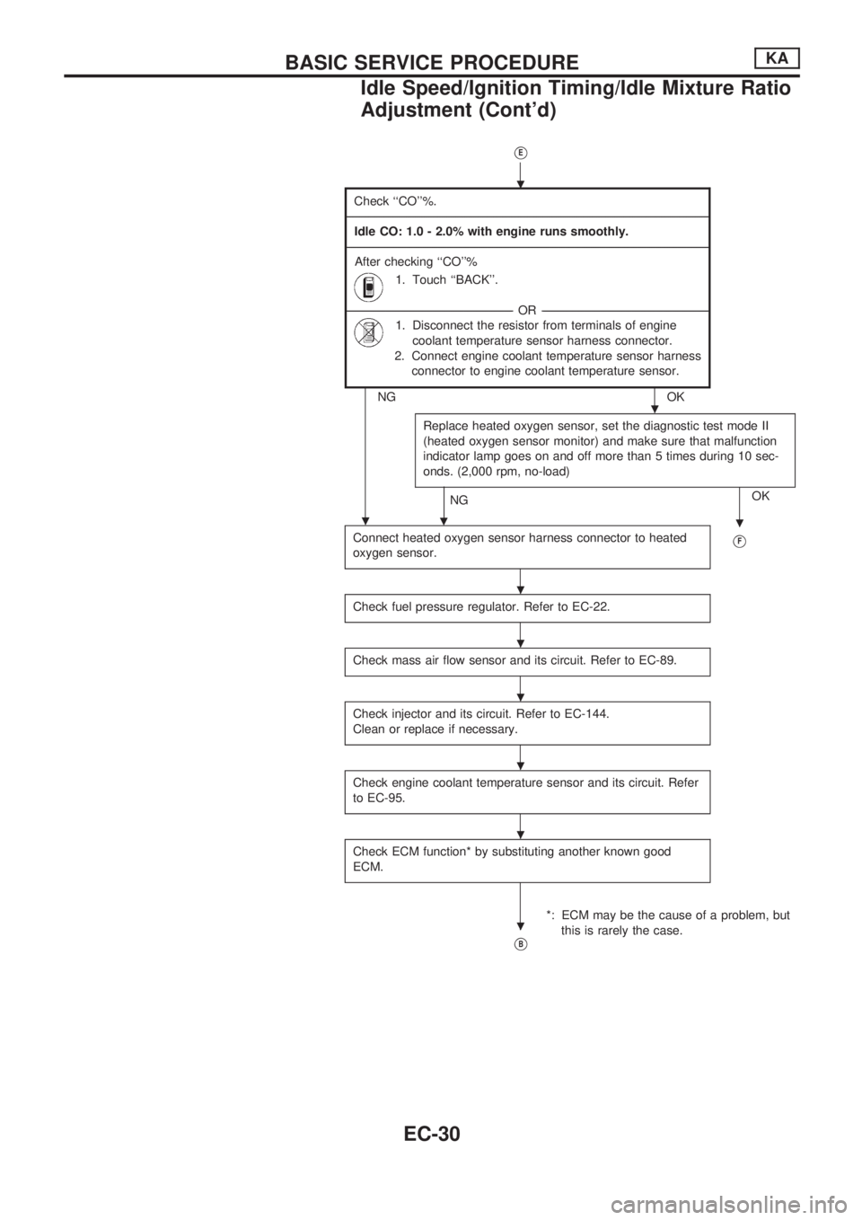
VE
Check ``CO''%.
-------------------------------------------------------------------------------------------------------------------------------------------------------------------------------------------------------------------------------------------------------------------------------------------------------------------------------------------------------------------------------------------------------------------------------------------------------
Idle CO: 1.0 - 2.0% with engine runs smoothly.
-------------------------------------------------------------------------------------------------------------------------------------------------------------------------------------------------------------------------------------------------------------------------------------------------------------------------------------------------------------------------------------------------------------------------------------------------------
After checking ``CO''%
1. Touch ``BACK''.
---------------------------------------------------------------------------------------------------------------------------------------------------------------------------------------------------------OR---------------------------------------------------------------------------------------------------------------------------------------------------------------------------------------------------------
1. Disconnect the resistor from terminals of engine
coolant temperature sensor harness connector.
2. Connect engine coolant temperature sensor harness
connector to engine coolant temperature sensor.
NG OK
Replace heated oxygen sensor, set the diagnostic test mode II
(heated oxygen sensor monitor) and make sure that malfunction
indicator lamp goes on and off more than 5 times during 10 sec-
onds. (2,000 rpm, no-load)
NGOK
.
Connect heated oxygen sensor harness connector to heated
oxygen sensor.VF
Check fuel pressure regulator. Refer to EC-22.
Check mass air flow sensor and its circuit. Refer to EC-89.
Check injector and its circuit. Refer to EC-144.
Clean or replace if necessary.
Check engine coolant temperature sensor and its circuit. Refer
to EC-95.
Check ECM function* by substituting another known good
ECM.
*: ECM may be the cause of a problem, but
this is rarely the case.
VB
.
.
..
.
.
.
.
.
.
BASIC SERVICE PROCEDUREKA
Idle Speed/Ignition Timing/Idle Mixture Ratio
Adjustment (Cont'd)
EC-30
Page 198 of 1659
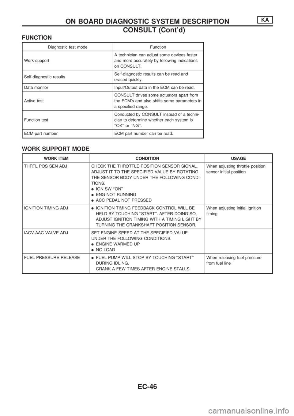
FUNCTION
Diagnostic test mode Function
Work supportA technician can adjust some devices faster
and more accurately by following indications
on CONSULT.
Self-diagnostic resultsSelf-diagnostic results can be read and
erased quickly.
Data monitor Input/Output data in the ECM can be read.
Active testCONSULT drives some actuators apart from
the ECM's and also shifts some parameters in
a specified range.
Function testConducted by CONSULT instead of a techni-
cian to determine whether each system is
``OK'' or ``NG''.
ECM part number ECM part number can be read.
WORK SUPPORT MODE
WORK ITEM CONDITION USAGE
THRTL POS SEN ADJ CHECK THE THROTTLE POSITION SENSOR SIGNAL.
ADJUST IT TO THE SPECIFIED VALUE BY ROTATING
THE SENSOR BODY UNDER THE FOLLOWING CONDI-
TIONS.
lIGN SW ``ON''
lENG NOT RUNNING
lACC PEDAL NOT PRESSEDWhen adjusting throttle position
sensor initial position
IGNITION TIMING ADJ
lIGNITION TIMING FEEDBACK CONTROL WILL BE
HELD BY TOUCHING ``START''. AFTER DOING SO,
ADJUST IGNITION TIMING WITH A TIMING LIGHT BY
TURNING THE CRANKSHAFT POSITION SENSOR.When adjusting initial ignition
timing
IACV-AAC VALVE ADJ SET ENGINE SPEED AT THE SPECIFIED VALUE
UNDER THE FOLLOWING CONDITIONS.
lENGINE WARMED UP
lNO-LOAD
FUEL PRESSURE RELEASE
lFUEL PUMP WILL STOP BY TOUCHING ``START''
DURING IDLING.
CRANK A FEW TIMES AFTER ENGINE STALLS.When releasing fuel pressure
from fuel line
ON BOARD DIAGNOSTIC SYSTEM DESCRIPTIONKA
CONSULT (Cont'd)
EC-46
Page 199 of 1659
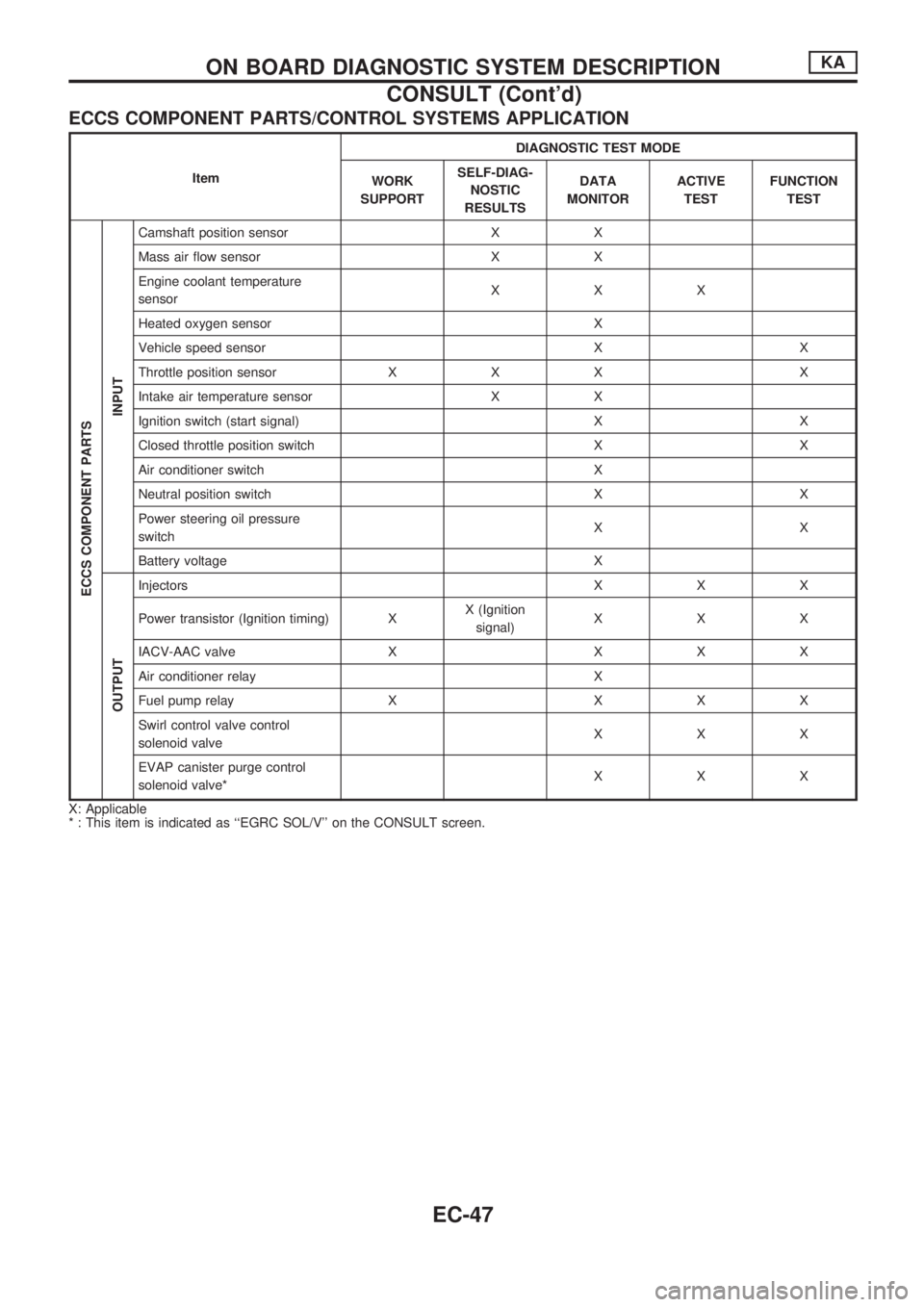
ECCS COMPONENT PARTS/CONTROL SYSTEMS APPLICATION
ItemDIAGNOSTIC TEST MODE
WORK
SUPPORTSELF-DIAG-
NOSTIC
RESULTSDATA
MONITORACTIVE
TESTFUNCTION
TEST
ECCS COMPONENT PARTS
INPUT
Camshaft position sensor X X
Mass air flow sensor X X
Engine coolant temperature
sensorXXX
Heated oxygen sensor X
Vehicle speed sensor X X
Throttle position sensor X X X X
Intake air temperature sensor X X
Ignition switch (start signal) X X
Closed throttle position switch X X
Air conditioner switch X
Neutral position switch X X
Power steering oil pressure
switchXX
Battery voltage X
OUTPUT
Injectors X X X
Power transistor (Ignition timing) XX (Ignition
signal)XXX
IACV-AAC valve X X X X
Air conditioner relay X
Fuel pump relay X X X X
Swirl control valve control
solenoid valveXXX
EVAP canister purge control
solenoid valve*XXX
X: Applicable
* : This item is indicated as ``EGRC SOL/V'' on the CONSULT screen.
ON BOARD DIAGNOSTIC SYSTEM DESCRIPTIONKA
CONSULT (Cont'd)
EC-47
Page 200 of 1659
![NISSAN PICK-UP 1998 Repair Manual SELF-DIAGNOSTIC MODE
Regarding items detected in ``SELF-DIAG RESULTS mode, refer to ``DIAGNOSTIC TROUBLE CODE
INDEX, EC-1.
DATA MONITOR MODE
Monitored item
[Unit]ECM
input
signalsMain
signalsDescr NISSAN PICK-UP 1998 Repair Manual SELF-DIAGNOSTIC MODE
Regarding items detected in ``SELF-DIAG RESULTS mode, refer to ``DIAGNOSTIC TROUBLE CODE
INDEX, EC-1.
DATA MONITOR MODE
Monitored item
[Unit]ECM
input
signalsMain
signalsDescr](/manual-img/5/57374/w960_57374-199.png)
SELF-DIAGNOSTIC MODE
Regarding items detected in ``SELF-DIAG RESULTS'' mode, refer to ``DIAGNOSTIC TROUBLE CODE
INDEX'', EC-1.
DATA MONITOR MODE
Monitored item
[Unit]ECM
input
signalsMain
signalsDescription Remarks
CMPSRPM
(POS) [rpm]
jj
lIndicates the engine speed computed
from the POS signal (1É signal) of the
camshaft position sensor.
MAS AIR/FL SE [V]
jjlThe signal voltage of the mass air flow
sensor is displayed.lWhen the engine is stopped, a certain
value is indicated.
COOLAN TEMP/S
[ÉC] or [ÉF]
jj
lThe engine coolant temperature (deter-
mined by the signal voltage of the engine
coolant temperature sensor) is displayed.lWhen the engine coolant temperature
sensor is open or short-circuited, ECM
enters fail-safe mode. The engine coolant
temperature determined by the ECM is
displayed.
O2 SEN [V]
jjlThe signal voltage of the heated oxygen
sensor is displayed.lLHD models only
M/R F/C MNT
[RICH/LEAN]
jj
lDisplay of heated oxygen sensor signal
during air-fuel ratio feedback control:
RICH ... means the mixture became
``rich'', and control is being affected
toward a leaner mixture.
LEAN ... means the mixture became
``lean'', and control is being affected
toward a rich mixture.lAfter turning ON the ignition switch,
``RICH'' is displayed until air-fuel mixture
ratio feedback control begins.
lWhen the air-fuel ratio feedback is
clamped, the value just before the clamp-
ing is displayed continuously.
lLHD models only
VHCL SPEED SE
[km/h] or [mph]
jjlThe vehicle speed computed from the
vehicle speed sensor signal is displayed.
BATTERY VOLT [V]
jjlThe power supply voltage of ECM is dis-
played.
THRTL POS SEN [V]
jjlThe throttle position sensor signal volt-
age is displayed.
INT/A TEMP SE
[ÉC] or [ÉF]
j
lThe intake air temperature (determined
by the signal voltage of the intake air
temperature sensor) is indicated.
START SIGNAL
[ON/OFF]
jjlIndicates [ON/OFF] condition from the
starter signal.lAfter starting the engine, [OFF] is
displayed regardless of the starter signal.
CLSD THL/POSI
[ON/OFF]
jj
lIndicates [ON/OFF] condition from the
throttle position sensor signal.
AIR COND SIG
[ON/OFF]
jj
lIndicates [ON/OFF] condition of the air
conditioner switch as determined by the
air conditioner signal.
P/N POSI SW
[ON/OFF]
jj
lIndicates [ON/OFF] condition from the
park/neutral position switch signal.
PW/ST SIGNAL
[ON/OFF]
jj
l[ON/OFF] condition of the power steering
oil pressure switch determined by the
power steering oil pressure signal is indi-
cated.
NOTE:
Any monitored item that does not match the vehicle being diagnosed is deleted from the display automatically.
ON BOARD DIAGNOSTIC SYSTEM DESCRIPTIONKA
CONSULT (Cont'd)
EC-48
Page 203 of 1659
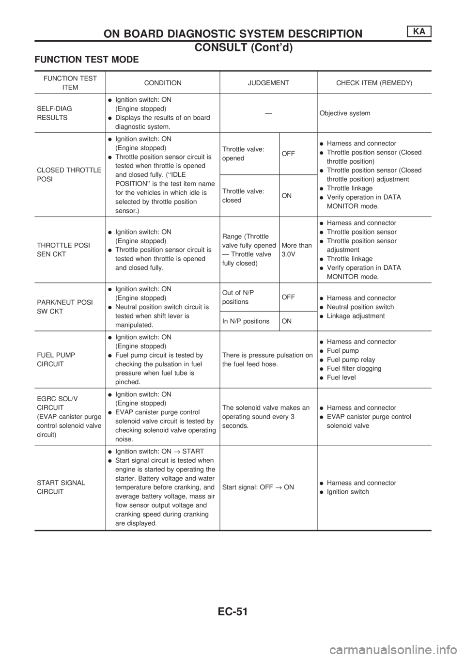
FUNCTION TEST MODE
FUNCTION TEST
ITEMCONDITION JUDGEMENT CHECK ITEM (REMEDY)
SELF-DIAG
RESULTS
lIgnition switch: ON
(Engine stopped)
lDisplays the results of on board
diagnostic system.Ð Objective system
CLOSED THROTTLE
POSI
lIgnition switch: ON
(Engine stopped)
lThrottle position sensor circuit is
tested when throttle is opened
and closed fully. (``IDLE
POSITION'' is the test item name
for the vehicles in which idle is
selected by throttle position
sensor.)Throttle valve:
openedOFF
lHarness and connector
lThrottle position sensor (Closed
throttle position)
lThrottle position sensor (Closed
throttle position) adjustment
lThrottle linkage
lVerify operation in DATA
MONITOR mode. Throttle valve:
closedON
THROTTLE POSI
SEN CKT
lIgnition switch: ON
(Engine stopped)
lThrottle position sensor circuit is
tested when throttle is opened
and closed fully.Range (Throttle
valve fully opened
Ð Throttle valve
fully closed)More than
3.0V
lHarness and connector
lThrottle position sensor
lThrottle position sensor
adjustment
lThrottle linkage
lVerify operation in DATA
MONITOR mode.
PARK/NEUT POSI
SW CKT
lIgnition switch: ON
(Engine stopped)
lNeutral position switch circuit is
tested when shift lever is
manipulated.Out of N/P
positionsOFF
lHarness and connector
lNeutral position switch
lLinkage adjustment
In N/P positions ON
FUEL PUMP
CIRCUIT
lIgnition switch: ON
(Engine stopped)
lFuel pump circuit is tested by
checking the pulsation in fuel
pressure when fuel tube is
pinched.There is pressure pulsation on
the fuel feed hose.
lHarness and connector
lFuel pump
lFuel pump relay
lFuel filter clogging
lFuel level
EGRC SOL/V
CIRCUIT
(EVAP canister purge
control solenoid valve
circuit)
lIgnition switch: ON
(Engine stopped)
lEVAP canister purge control
solenoid valve circuit is tested by
checking solenoid valve operating
noise.The solenoid valve makes an
operating sound every 3
seconds.lHarness and connector
lEVAP canister purge control
solenoid valve
START SIGNAL
CIRCUIT
lIgnition switch: ON®START
lStart signal circuit is tested when
engine is started by operating the
starter. Battery voltage and water
temperature before cranking, and
average battery voltage, mass air
flow sensor output voltage and
cranking speed during cranking
are displayed.Start signal: OFF®ON
lHarness and connector
lIgnition switch
ON BOARD DIAGNOSTIC SYSTEM DESCRIPTIONKA
CONSULT (Cont'd)
EC-51
Page 204 of 1659
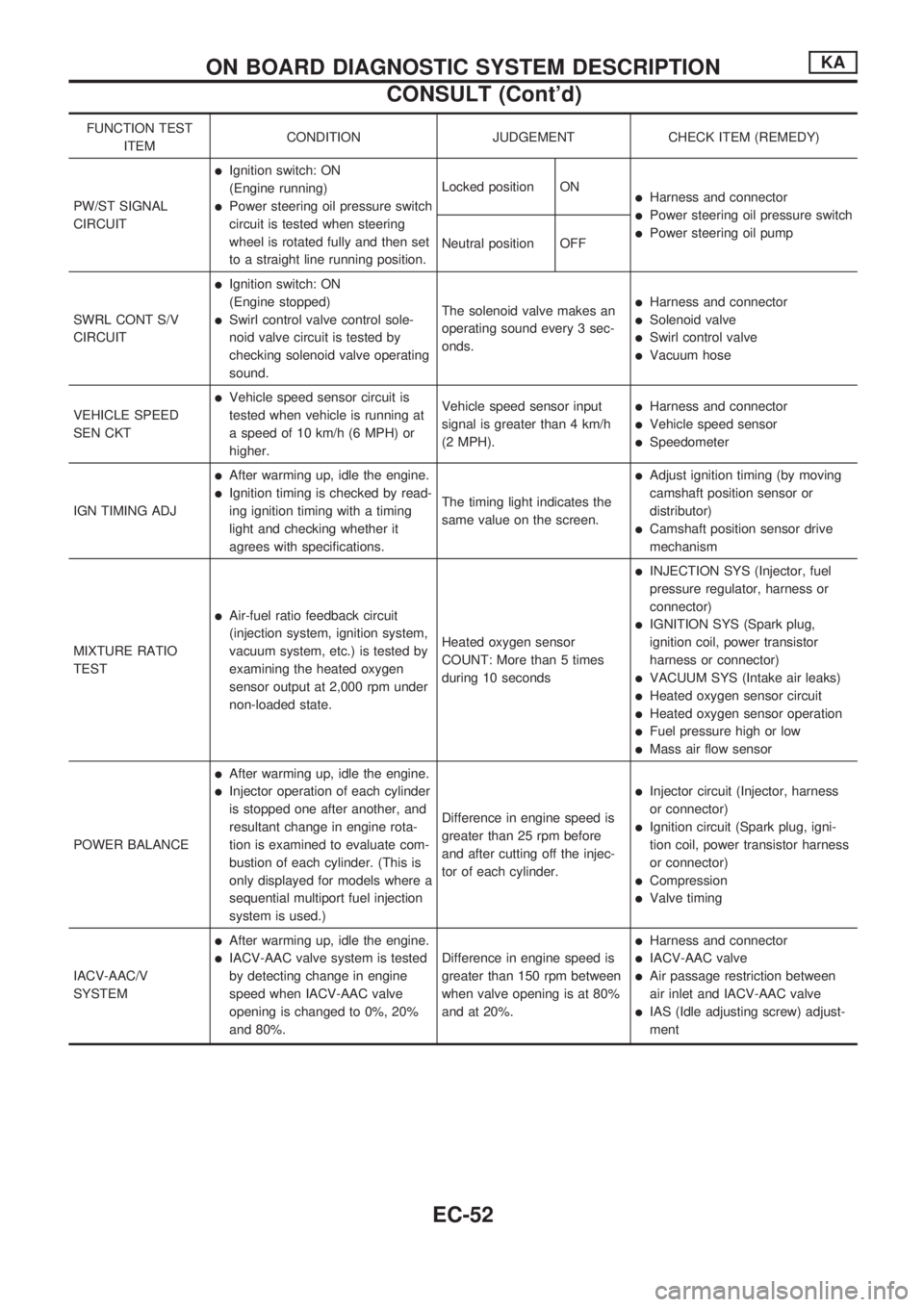
FUNCTION TEST
ITEMCONDITION JUDGEMENT CHECK ITEM (REMEDY)
PW/ST SIGNAL
CIRCUIT
lIgnition switch: ON
(Engine running)
lPower steering oil pressure switch
circuit is tested when steering
wheel is rotated fully and then set
to a straight line running position.Locked position ONlHarness and connector
lPower steering oil pressure switch
lPower steering oil pump
Neutral position OFF
SWRL CONT S/V
CIRCUIT
lIgnition switch: ON
(Engine stopped)
lSwirl control valve control sole-
noid valve circuit is tested by
checking solenoid valve operating
sound.The solenoid valve makes an
operating sound every 3 sec-
onds.
lHarness and connector
lSolenoid valve
lSwirl control valve
lVacuum hose
VEHICLE SPEED
SEN CKT
lVehicle speed sensor circuit is
tested when vehicle is running at
a speed of 10 km/h (6 MPH) or
higher.Vehicle speed sensor input
signal is greater than 4 km/h
(2 MPH).lHarness and connector
lVehicle speed sensor
lSpeedometer
IGN TIMING ADJ
lAfter warming up, idle the engine.
lIgnition timing is checked by read-
ing ignition timing with a timing
light and checking whether it
agrees with specifications.The timing light indicates the
same value on the screen.
lAdjust ignition timing (by moving
camshaft position sensor or
distributor)
lCamshaft position sensor drive
mechanism
MIXTURE RATIO
TEST
lAir-fuel ratio feedback circuit
(injection system, ignition system,
vacuum system, etc.) is tested by
examining the heated oxygen
sensor output at 2,000 rpm under
non-loaded state.Heated oxygen sensor
COUNT: More than 5 times
during 10 seconds
lINJECTION SYS (Injector, fuel
pressure regulator, harness or
connector)
lIGNITION SYS (Spark plug,
ignition coil, power transistor
harness or connector)
lVACUUM SYS (Intake air leaks)
lHeated oxygen sensor circuit
lHeated oxygen sensor operation
lFuel pressure high or low
lMass air flow sensor
POWER BALANCE
lAfter warming up, idle the engine.
lInjector operation of each cylinder
is stopped one after another, and
resultant change in engine rota-
tion is examined to evaluate com-
bustion of each cylinder. (This is
only displayed for models where a
sequential multiport fuel injection
system is used.)Difference in engine speed is
greater than 25 rpm before
and after cutting off the injec-
tor of each cylinder.lInjector circuit (Injector, harness
or connector)
lIgnition circuit (Spark plug, igni-
tion coil, power transistor harness
or connector)
lCompression
lValve timing
IACV-AAC/V
SYSTEM
lAfter warming up, idle the engine.
lIACV-AAC valve system is tested
by detecting change in engine
speed when IACV-AAC valve
opening is changed to 0%, 20%
and 80%.Difference in engine speed is
greater than 150 rpm between
when valve opening is at 80%
and at 20%.
lHarness and connector
lIACV-AAC valve
lAir passage restriction between
air inlet and IACV-AAC valve
lIAS (Idle adjusting screw) adjust-
ment
ON BOARD DIAGNOSTIC SYSTEM DESCRIPTIONKA
CONSULT (Cont'd)
EC-52