Page 57 of 65
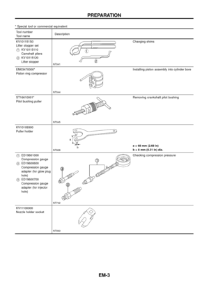
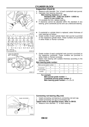
6. Measure connecting rod side clearance.
Connecting rod side clearance:
Standard
0.20 - 0.30 mm (0.0079 - 0.0118 in)
Limit
0.40 mm (0.0157 in)
If beyond the limit, replace connecting rod and/or crankshaft.
SEM760B
CYLINDER BLOCK
Assembly (Cont'd)
EM-56
Page 58 of 65
General Speci®cations
Cylinder arrangement In-line 6
Displacement cm
3(cu in) 2,826 (172.44)
Bore and stroke mm (in) 85 x 83 (3.35 x 3.27)
Valve arrangement OHC
Firing order 1-5-3-6-2-4
Number of piston rings
Compression 2
Oil 1
Number of main bearings 7
Compression ratio 21.8
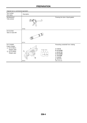
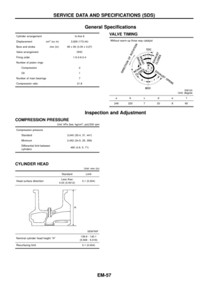
VALVE TIMING
Without warm-up three way catalyst
EM120Unit: degree
abcde f
248 220 7 33 8 60
Inspection and Adjustment
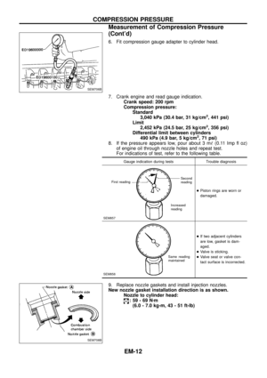
COMPRESSION PRESSURE
Unit: kPa (bar, kg/cm2, psi)/200 rpm
Compression pressure
Standard 3,040 (30.4, 31, 441)
Minimum 2,452 (24.5, 25, 356)
Differential limit between
cylinders490 (4.9, 5, 71)
CYLINDER HEAD
Unit: mm (in)
Standard Limit
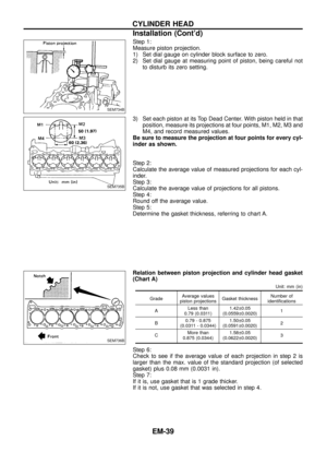
Head surface distortionLess than
0.03 (0.0012)0.1 (0.004)
SEM795F
Nominal cylinder head height ``H''139.9 - 140.1
(5.508 - 5.516)
Resurfacing limit 0.1 (0.004)
SERVICE DATA AND SPECIFICATIONS (SDS)
EM-57
Page 59 of 65

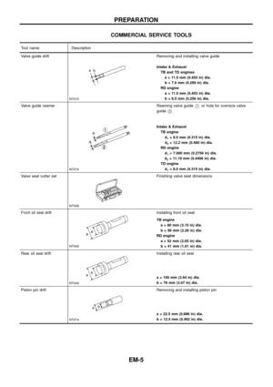
SEM188A
Valve head diameter ``D
Intake 39.0 - 39.3 (1.535 - 1.547)
Exhaust 32.0 - 32.3 (1.260 - 1.272)
Valve length ``L
Intake101.53 - 101.97
(3.9972 - 4.0146)
Exhaust101.38")
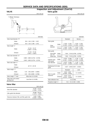
VA LV E
Unit: mm (in)
SEM188A
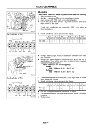
Valve head diameter ``D''
Intake 39.0 - 39.3 (1.535 - 1.547)
Exhaust 32.0 - 32.3 (1.260 - 1.272)
Valve length ``L''
Intake101.53 - 101.97
(3.9972 - 4.0146)
Exhaust101.38 - 101.82
(3.9913 - 4.0087)
Valve stem diameter ``d''
Intake 6.965 - 6.980 (0.2742 - 0.2748)
Exhaust 6.945 - 6.960 (0.2734 - 0.2740)
Valve seat angle ``a''
Intake
45É15¢- 45É45¢
Exhaust
Valve margin ``T''
Intake 1.35 - 1.65 (0.0531 - 0.0650)
Exhaust 1.65 - 1.95 (0.0650 - 0.0768)
Valve margin ``T'' limit More than 0.5 (0.020)
Valve stem end surface
grinding limitLess than 0.2 (0.008)
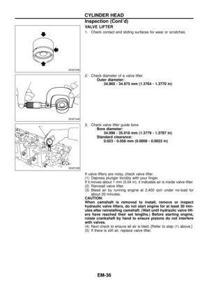
Valve lifter
Unit: mm (in)
Valve lifter diameter34.960 - 34.975
(1.3764 - 1.3770)
Lifter guide hole diameter34.998 - 35.018
(1.3779 - 1.3787)
Clearance between lifter and lifter guide hole0.023 - 0.058
(0.0009 - 0.0023)
Valve guide
Unit: mm (in)
SEM796F
Standard Service
Valve guide
Outer
diameterIntake11.023 - 11.034
(0.4340 - 0.4344)11.233 - 11.234
(0.4422 - 0.4423)
Exhaust11.023 - 11.034
(0.4340 - 0.4344)11.233 - 11.234
(0.4422 - 0.4423)
Valve guide
Inner diam-
eter (Fin-
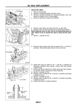
ished size)Intake 7.000 - 7.018 (0.2756 - 0.2763)
Exhaust 7.000 - 7.018 (0.2756 - 0.2763)
Cylinder head
valve guide
hole diameterIntake10.975 - 10.996
(0.4321 - 0.4329)11.185 - 11.196
(0.4404 - 0.4408)
Exhaust10.975 - 10.996
(0.4321 - 0.4329)11.185 - 11.196
(0.4404 - 0.4408)
Interference ®t of valve
guide0.027 - 0.059 (0.0011 - 0.0023)
Standard Limit
Stem to guide
clearanceIntake0.020 - 0.050
(0.0008 - 0.0020)0.1 (0.004)
Exhaust0.040 - 0.070
(0.0016 - 0.0028)0.1 (0.004)
Valve de¯ection limit 0.2 (0.008)
Projection length ``L'' 10.2 - 10.4 (0.402 - 0.409)
SERVICE DATA AND SPECIFICATIONS (SDS)
Inspection and Adjustment (Cont'd)
EM-58
Page 60 of 65
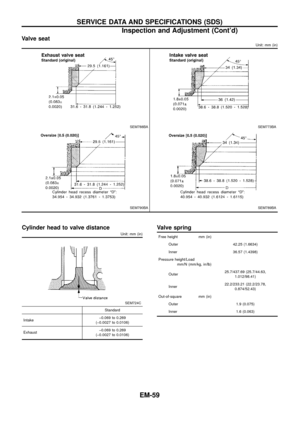
Valve seat
Unit: mm (in)
SEM788BASEM773BA
SEM790BASEM789BA
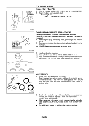
Cylinder head to valve distance
Unit: mm (in)
SEM724C
Standard
Intakeþ0.069 to 0.269
(þ0.0027 to 0.0106)
Exhaustþ0.069 to 0.269
(þ0.0027 to 0.0106)
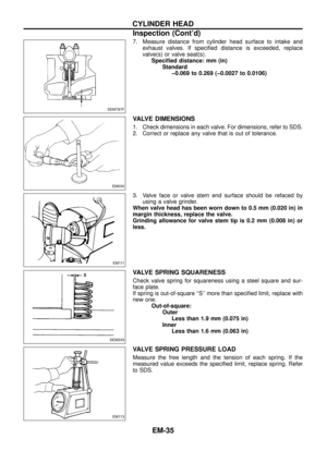
Valve spring
Free height mm (in)
Outer 42.25 (1.6634)
Inner 36.57 (1.4398)
Pressure height/Load
mm/N (mm/kg, in/lb)
Outer25.7/437.69 (25.7/44.63,
1.012/98.41)
Inner22.2/233.21 (22.2/23.78,
0.874/52.43)
Out-of-square mm (in)
Outer 1.9 (0.075)
Inner 1.6 (0.063)
SERVICE DATA AND SPECIFICATIONS (SDS)
Inspection and Adjustment (Cont'd)
EM-59
Page 61 of 65
 Identi®cation mark
2.90 (0.1142) 2.90
2.85 (0.1122) 2.85
2.80 (0.1102) 2.80
2.75 (0.1083) 2.75
2.70 (0.1063) 2.70
2.65 (0.1043) 2.65
2.60 (0.1024) 2.60
2.55 (0.1004)")
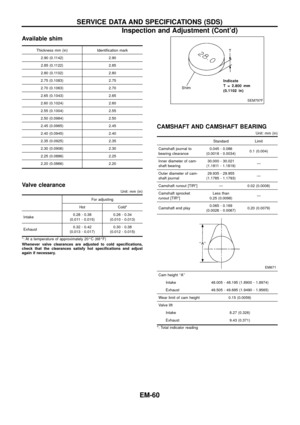
Available shim
Thickness mm (in) Identi®cation mark
2.90 (0.1142) 2.90
2.85 (0.1122) 2.85
2.80 (0.1102) 2.80
2.75 (0.1083) 2.75
2.70 (0.1063) 2.70
2.65 (0.1043) 2.65
2.60 (0.1024) 2.60
2.55 (0.1004) 2.55
2.50 (0.0984) 2.50
2.45 (0.0965) 2.45
2.40 (0.0945) 2.40
2.35 (0.0925) 2.35
2.30 (0.0906) 2.30
2.25 (0.0886) 2.25
2.20 (0.0866) 2.20
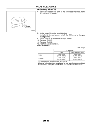
Valve clearance
Unit: mm (in)
For adjusting
Hot Cold*
Intake0.28 - 0.38
(0.011 - 0.015)0.26 - 0.34
(0.010 - 0.013)
Exhaust0.32 - 0.42
(0.013 - 0.017)0.30 - 0.38
(0.012 - 0.015)
*: At a temperature of approximately 20ÉC (68ÉF)
Whenever valve clearances are adjusted to cold speci®cations,
check that the clearances satisfy hot speci®cations and adjust
again if necessary.
CAMSHAFT AND CAMSHAFT BEARING
Unit: mm (in)
Standard Limit
Camshaft journal to
bearing clearance0.045 - 0.086
(0.0018 - 0.0034)0.1 (0.004)
Inner diameter of cam-
shaft bearing30.000 - 30.021
(1.1811 - 1.1819)Ð
Outer diameter of cam-
shaft journal29.935 - 29.955
(1.1785 - 1.1793)Ð
Camshaft runout [TIR*] Ð 0.02 (0.0008)
Camshaft sprocket
runout [TIR*]Less than
0.25 (0.0098)Ð
Camshaft end play0.065 - 0.169
(0.0026 - 0.0067)0.20 (0.0079)
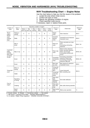
EM671
Cam height ``A''
Intake 48.005 - 48.195 (1.8900 - 1.8974)
Exhaust 49.505 - 49.695 (1.9490 - 1.9565)
Wear limit of cam height 0.15 (0.0059)
Valve lift
Intake 8.27 (0.326)
Exhaust 9.43 (0.371)
*: Total indicator reading
SEM797F
SERVICE DATA AND SPECIFICATIONS (SDS)
Inspection and Adjustment (Cont'd)
EM-60
Page 62 of 65

SEM964EA
SEM686DA
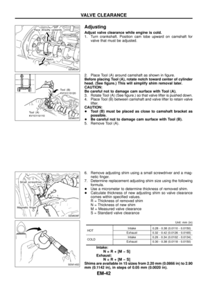
Surface ¯atness
Standard Less than 0.03 (0.0012)
Limit 0.1 (0.004)
Cylinder bore
Inner diameter
Standard
Grade No. 1 85.000 - 85.010 (3.3465 - 3.3468)
G")
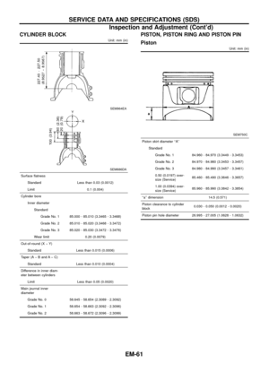
CYLINDER BLOCK
Unit: mm (in)
SEM964EA
SEM686DA
Surface ¯atness
Standard Less than 0.03 (0.0012)
Limit 0.1 (0.004)
Cylinder bore
Inner diameter
Standard
Grade No. 1 85.000 - 85.010 (3.3465 - 3.3468)
Grade No. 2 85.010 - 85.020 (3.3468 - 3.3472)
Grade No. 3 85.020 - 85.030 (3.3472 - 3.3476)
Wear limit 0.20 (0.0079)
Out-of-round (X þ Y)
Standard Less than 0.015 (0.0006)
Taper (A þ B and A þ C)
Standard Less than 0.010 (0.0004)
Difference in inner diam-
eter between cylinders
Limit Less than 0.05 (0.0020)
Main journal inner
diameter
Grade No. 0 58.645 - 58.654 (2.3089 - 2.3092)
Grade No. 1 58.654 - 58.663 (2.3092 - 2.3096)
Grade No. 2 58.663 - 58.672 (2.3096 - 2.3099)
PISTON, PISTON RING AND PISTON PIN
Piston
Unit: mm (in)
SEM750C
Piston skirt diameter ``A''
Standard
Grade No. 1 84.960 - 84.970 (3.3449 - 3.3453)
Grade No. 2 84.970 - 84.980 (3.3453 - 3.3457)
Grade No. 3 84.980 - 84.990 (3.3457 - 3.3461)
0.50 (0.0197) over-
size (Service)85.460 - 85.490 (3.3646 - 3.3657)
1.00 (0.0394) over-
size (Service)85.960 - 85.990 (3.3842 - 3.3854)
``a'' dimension 14.5 (0.571)
Piston clearance to cylinder
block0.030 - 0.050 (0.0012 - 0.0020)
Piston pin hole diameter 26.995 - 27.005 (1.0628 - 1.0632)
SERVICE DATA AND SPECIFICATIONS (SDS)
Inspection and Adjustment (Cont'd)
EM-61
Page 63 of 65

Side clearance
To p
Standard0.060 - 0.093
(0.0024 - 0.0037)
Limit 0.1 (0.004)
2nd
Standard0.040 - 0.073
(0.0016 - 0.0029)
Limit 0.1 (0.004)
Oil
Standard0.030 - 0.063
(0.0012")
Piston ring
Unit: mm (in)
Side clearance
To p
Standard0.060 - 0.093
(0.0024 - 0.0037)
Limit 0.1 (0.004)
2nd
Standard0.040 - 0.073
(0.0016 - 0.0029)
Limit 0.1 (0.004)
Oil
Standard0.030 - 0.063
(0.0012 - 0.0025)
Limit Ð
Ring gap
To p
Standard0.20 - 0.28
(0.0079 - 0.0110)
Limit 1.0 (0.039)
2nd
Standard0.38 - 0.53
(0.0150 - 0.0209)
Limit 1.0 (0.039)
Oil
Standard0.30 - 0.56
(0.0118 - 0.0220)
Limit 1.0 (0.039)
Piston pin
Unit: mm (in)
Piston pin outer diameter 26.994 - 27.000 (1.0628 - 1.0630)
Interference ®t of piston pin
to piston0.002 - 0.006 (0.0001 - 0.0002)
Piston pin to connecting rod
bushing clearance
Standard 0.025 - 0.044 (0.0010 - 0.0017)
* Values measured at ambient temperature of 20ÉC (68ÉF)
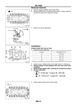
CONNECTING ROD
Unit: mm (in)
Center distance 140.0 (5.512)
Bend [per 100 (3.94)]
Limit 0.025 (0.0010)
Torsion [per 100 (3.94)]
Limit 0.025 (0.0010)
Connecting rod small end
inner diameter30.000 - 30.013 (1.1811 - 1.1816)
Piston pin bushing inner
diameter*27.025 - 27.038 (1.0640 - 1.0645)
Connecting rod big end inner
diameter
Grade No. 0 53.000 - 53.007 (2.0866 - 2.0869)
Grade No. 1 53.007 - 53.013 (2.0869 - 2.0871)
Side clearance
Standard 0.20 - 0.30 (0.0079 - 0.0118)
Limit 0.40 (0.0157)
*: After installing in connecting rod
SERVICE DATA AND SPECIFICATIONS (SDS)
Inspection and Adjustment (Cont'd)
EM-62
Page 64 of 65

Main journal dia. ``Dm
Grade No. 0 54.967 - 54.975 (2.1641 - 2.1644)
Grade No. 1 54.959 - 54.967 (2.1637 - 2.1641)
Grade No. 2 54.951 - 54.959 (2.1634 - 2.1637)
Pin journal")
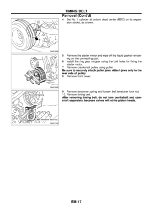
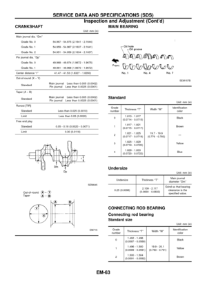
CRANKSHAFT
Unit: mm (in)
Main journal dia. ``Dm''
Grade No. 0 54.967 - 54.975 (2.1641 - 2.1644)
Grade No. 1 54.959 - 54.967 (2.1637 - 2.1641)
Grade No. 2 54.951 - 54.959 (2.1634 - 2.1637)
Pin journal dia. ``Dp''
Grade No. 0 49.968 - 49.974 (1.9672 - 1.9675)
Grade No. 1 49.961 - 49.968 (1.9670 - 1.9672)
Center distance ``r'' 41.47 - 41.53 (1.6327 - 1.6350)
Out-of-round (X þ Y)
Standard
Main journal Less than 0.005 (0.0002)
Pin journal Less than 0.0025 (0.0001)
Taper (A þ B)
Standard
Main journal Less than 0.005 (0.0002)
Pin journal Less than 0.0025 (0.0001)
Runout [TIR]
Standard Less than 0.025 (0.0010)
Limit Less than 0.05 (0.0020)
Free end play
Standard 0.05 - 0.18 (0.0020 - 0.0071)
Limit 0.30 (0.0118)
SEM645
EM715
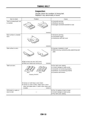
MAIN BEARING
SEM157B
Standard
Unit: mm (in)
Grade
numberThickness ``T'' Width ``W''Identi®cation
color
01.813 - 1.817
(0.0714 - 0.0715)
19.7 - 19.9
(0.776 - 0.783)Black
11.817 - 1.821
(0.0715 - 0.0717)Brown
21.821 - 1.825
(0.0717 - 0.0719)Ð
31.825 - 1.829
(0.0719 - 0.0720)Yellow
41.829 - 1.833
(0.0720 - 0.0722)Blue
Undersize
Unit: mm (in)
Undersize Thickness ``T''Main journal
diameter ``Dm''
0.25 (0.0098)2.109 - 2.117
(0.0830 - 0.0833)Grind so that bearing
clearance is the
speci®ed value.
CONNECTING ROD BEARING
Connecting rod bearing
Standard size
Unit: mm (in)
Grade
numberThickness ``T'' Width ``W''Identi®cation
color
01.492 - 1.496
(0.0587 - 0.0589)
19.9 - 20.1
(0.783 - 0.791)Black
11.496 - 1.500
(0.0589 - 0.0591)Yellow
21.500 - 1.504
(0.0591 - 0.0592)Brown
SERVICE DATA AND SPECIFICATIONS (SDS)
Inspection and Adjustment (Cont'd)
EM-63


Limit
0.40 mm (0.0157 in)
If beyond the limit, replace connecting rod and/or crank")
 2,826 (172.44)
Bore and stroke mm (in) 85 x 83 (3.35 x 3.27)
Valve arrangement OHC
Firing order 1-5-3-6-2-4
Number of pis")

SEM788BASEM773BA
SEM790BASEM789BA
Cylinder head to valve distance
Unit: mm (in)
SEM724C
Standard
Intakeþ0.069 to 0.269
(þ0.0027 to 0.0106)
Exhaustþ0.069 to 0.269
(þ0.0027")