Page 49 of 65

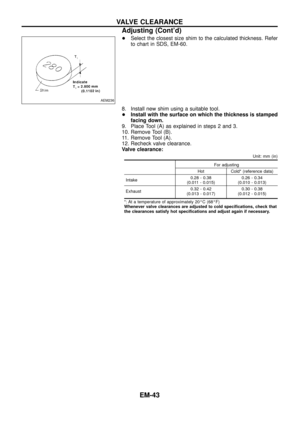
3. Calculate piston pin clearance.
dp þ Dp = þ0.004 to 0 mm (þ0.0002 to 0 in)
If it")
2. Measure outer diameter of piston pin ``Dp''.
Standard diameter ``Dp'':
26.994 - 27.000 mm (1.0628 - 1.0630 in)
3. Calculate piston pin clearance.
dp þ Dp = þ0.004 to 0 mm (þ0.0002 to 0 in)
If it exceeds the above value, replace piston assembly with pin.
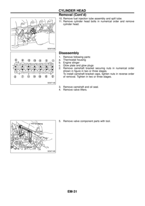
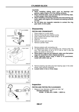
PISTON RING SIDE CLEARANCE
Side clearance:
Top ring
0.060 - 0.093 mm (0.0024 - 0.0037 in)
2nd ring
0.040 - 0.073 mm (0.0016 - 0.0029 in)
Max. limit of side clearance:
0.1 mm (0.004 in)
If out of speci®cation, replace piston ring. If clearance exceeds
maximum limit with new ring, replace piston.
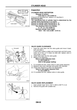
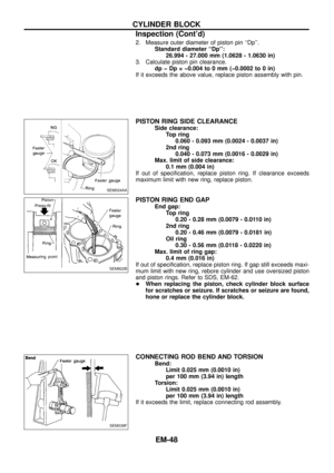
PISTON RING END GAP
End gap:
Top ring
0.20 - 0.28 mm (0.0079 - 0.0110 in)
2nd ring
0.20 - 0.46 mm (0.0079 - 0.0181 in)
Oil ring
0.30 - 0.56 mm (0.0118 - 0.0220 in)
Max. limit of ring gap:
0.4 mm (0.016 in)
If out of speci®cation, replace piston ring. If gap still exceeds maxi-
mum limit with new ring, rebore cylinder and use oversized piston
and piston rings. Refer to SDS, EM-62.
+When replacing the piston, check cylinder block surface
for scratches or seizure. If scratches or seizure are found,
hone or replace the cylinder block.
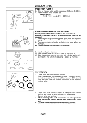
CONNECTING ROD BEND AND TORSION
Bend:
Limit 0.025 mm (0.0010 in)
per 100 mm (3.94 in) length
Torsion:
Limit 0.025 mm (0.0010 in)
per 100 mm (3.94 in) length
If it exceeds the limit, replace connecting rod assembly.
SEM024AA
SEM822B
SEM038F
CYLINDER BLOCK
Inspection (Cont'd)
EM-48
Page 50 of 65

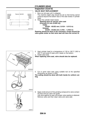
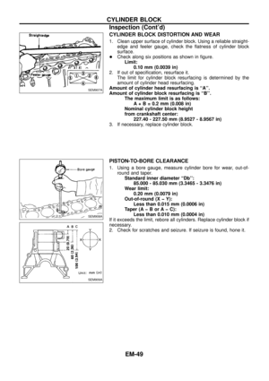
CYLINDER BLOCK DISTORTION AND WEAR
1. Clean upper surface of cylinder block. Using a reliable straight-
edge and feeler gauge, check the ¯atness of cylinder block
surface.
+Check along six positions as shown in ®gure.
Limit:
0.10 mm (0.0039 in)
2. If out of speci®cation, resurface it.
The limit for cylinder block resurfacing is determined by the
amount of cylinder head resurfacing.
Amount of cylinder head resurfacing is ``A''.
Amount of cylinder block resurfacing is ``B''.
The maximum limit is as follows:
A + B = 0.2 mm (0.008 in)
Nominal cylinder block height
from crankshaft center:
227.40 - 227.50 mm (8.9527 - 8.9567 in)
3. If necessary, replace cylinder block.
PISTON-TO-BORE CLEARANCE
1. Using a bore gauge, measure cylinder bore for wear, out-of-
round and taper.
Standard inner diameter ``Db'':
85.000 - 85.030 mm (3.3465 - 3.3476 in)
Wear limit:
0.20 mm (0.0079 in)
Out-of-round (X þ Y):
Less than 0.015 mm (0.0006 in)
Taper (A þ B or A þ C):
Less than 0.010 mm (0.0004 in)
If it exceeds the limit, rebore all cylinders. Replace cylinder block if
necessary.
2. Check for scratches and seizure. If seizure is found, hone it.
SEM907A
SEM908A
SEM909A
CYLINDER BLOCK
Inspection (Cont'd)
EM-49
Page 51 of 65
:
18 mm (0.71 in)
4. Check that piston-to-bore clearance is within speci®")
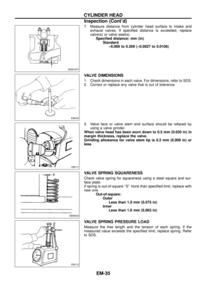
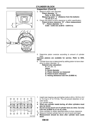
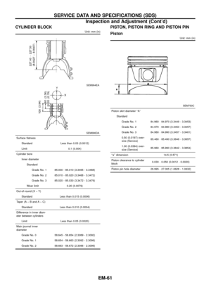
3. Measure piston skirt diameter.
Piston diameter ``A'':
Refer to SDS, EM-61.
Measuring point ``a'' (Distance from the bottom):
18 mm (0.71 in)
4. Check that piston-to-bore clearance is within speci®cation.
Piston-to-bore clearance ``B'' = Bore measurement
``C'' þ Piston diameter ``A'':
0.025 - 0.045 mm (0.0010 - 0.0018 in)
5. Determine piston oversize according to amount of cylinder
wear.
Oversize pistons are available for service. Refer to SDS,
EM-61.
6. Cylinder bore size is determined by adding piston-to-bore clear-
ance to piston diameter ``A''.
Rebored size calculation:
D=A+BþC
where,
D: Bored diameter
A: Piston diameter as measured
B: Piston-to-bore clearance
C: Honing allowance 0.02 mm (0.0008 in)
7. Install main bearing cap and tighten bolts to 90 to 100 Nzm (9.2
to 10.2 kg-m, 67 to 74 ft-lb). This will prevent distortion of cyl-
inder bores.
8. Cut cylinder bores.
+When any cylinder needs boring, all other cylinders must
also be bored.
+Do not cut too much out of cylinder bore at a time. Cut only
0.05 mm (0.0020 in) or so at a time.
9. Hone cylinders to obtain speci®ed piston-to-bore clearance.
10. Measure ®nished cylinder bore for out-of-round and taper.
+Measurement should be done after cylinder bore cools
down.
SEM181B
SEM755B
CYLINDER BLOCK
Inspection (Cont'd)
EM-50
Page 52 of 65
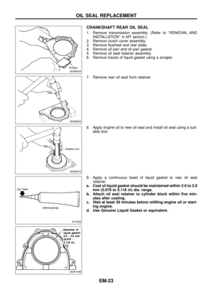
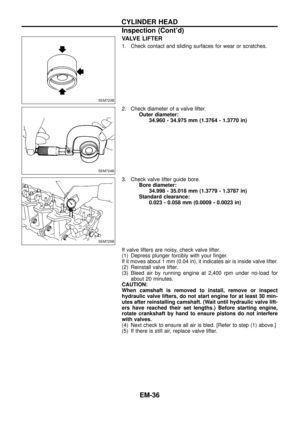
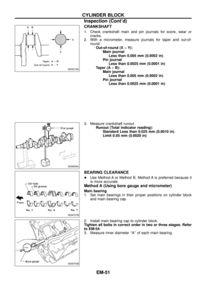
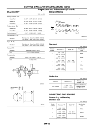
CRANKSHAFT
1. Check crankshaft main and pin journals for score, wear or
cracks.
2. With a micrometer, measure journals for taper and out-of-
round.
Out-of-round (X þ Y):
Main journal
Less than 0.005 mm (0.0002 in)
Pin journal
Less than 0.0025 mm (0.0001 in)
Taper (A þ B):
Main journal
Less than 0.005 mm (0.0002 in)
Pin journal
Less than 0.0025 mm (0.0001 in)
3. Measure crankshaft runout.
Runout (Total indicator reading):
Standard Less than 0.025 mm (0.0010 in)
Limit 0.05 mm (0.0020 in)
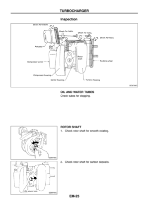
BEARING CLEARANCE
+Use Method A or Method B. Method A is preferred because it
is more accurate.
Method A (Using bore gauge and micrometer)
Main bearing
1. Set main bearings in their proper positions on cylinder block
and main bearing cap.
2. Install main bearing cap to cylinder block.
Tighten all bolts in correct order in two or three stages. Refer
to EM-54.
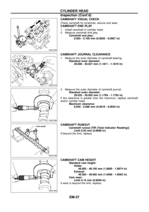
3. Measure inner diameter ``A'' of each main bearing.
SEM316A
SEM906A
SEM157B
SEM753B
CYLINDER BLOCK
Inspection (Cont'd)
EM-51
Page 53 of 65

Limit 0.12 mm (0")
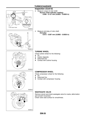
4. Measure outer diameter ``Dm'' of each crankshaft main journal.
5. Calculate main bearing clearance.
Main bearing clearance = A þ Dm:
Standard 0.036 - 0.063 mm (0.0014 - 0.0025 in)
Limit 0.12 mm (0.0047 in)
If it exceeds the limit, replace bearing.
+If clearance cannot be adjusted within the standard of any
bearing, grind crankshaft journal and use undersized bearing.
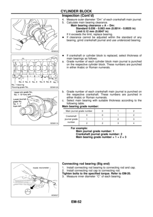
+If crankshaft or cylinder block is replaced, select thickness of
main bearings as follows:
a. Grade number of each cylinder block main journal is punched
on the respective cylinder block. These numbers are punched
in either Arabic or Roman numerals.
b. Grade number of each crankshaft main journal is punched on
the respective crankshaft. These numbers are punched in
either Arabic or Roman numerals.
c. Select main bearing with suitable thickness according to the
following table.
Main bearing grade number:
Main journal grade number 0 1 2
Crankshaft
journal grade
number0012
1123
2234
For example:
Main journal grade number: 1
Crankshaft journal grade number: 2
Main bearing grade number=1+2=3
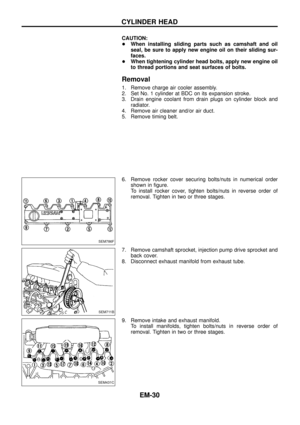
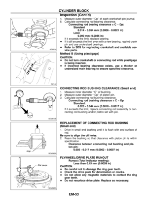
Connecting rod bearing (Big end)
1. Install connecting rod bearing to connecting rod and cap.
2. Install connecting rod cap to connecting rod.
Tighten bolts to the speci®ed torque. Refer to EM-20.
3. Measure inner diameter ``C'' of each bearing.
AEM033
SEM912A
SEM911A
AEM027
CYLINDER BLOCK
Inspection (Cont'd)
EM-52
Page 54 of 65

L")
4. Measure outer diameter ``Dp'' of each crankshaft pin journal.
5. Calculate connecting rod bearing clearance.
Connecting rod bearing clearance=CþDp:
Standard
0.014 - 0.054 mm (0.0006 - 0.0021 in)
Limit
0.090 mm (0.0035 in)
If it exceeds the limit, replace bearing.
+If it still exceeds the limit even with a new bearing, regrind crank
pin and use undersized bearings.
+Refer to SDS for regrinding crankshaft and available ser-
vice parts.
Method B (Using plastigage)
CAUTION:
+Do not turn crankshaft or connecting rod while plastigage
is being inserted.
+If incorrect bearing clearance exists, use a thicker or
undersized main bearing to ensure speci®ed clearance.
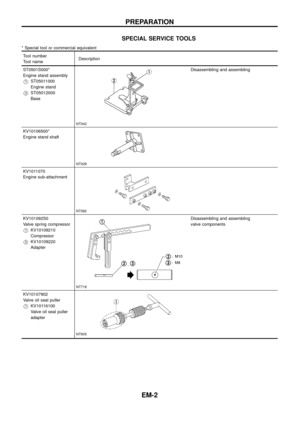
CONNECTING ROD BUSHING CLEARANCE (Small end)
1. Measure inner diameter ``C'' of bushing.
2. Measure outer diameter ``Dp'' of piston pin.
3. Calculate connecting rod bushing clearance.
Connecting rod bushing clearance=CþDp
Standard:
0.025 - 0.044 mm (0.0010 - 0.0017 in)
If it exceeds the limit, replace connecting rod assembly or con-
necting rod bushing and/or piston set with pin.
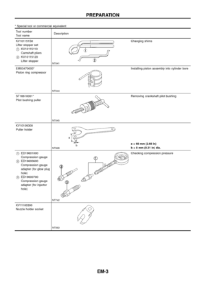
REPLACEMENT OF CONNECTING ROD BUSHING
(Small end)
1. Drive in small end bushing until it is ¯ush with end surface of
rod.
Be sure to align the oil holes.
2. Ream the bushing so that clearance with piston pin is within
speci®cation.
Clearance between connecting rod bushing and pis-
ton pin:
0.005 - 0.017 mm (0.0002 - 0.0007 in)
FLYWHEEL/DRIVE PLATE RUNOUT
Runout (Total indicator reading):
Less than 0.15 mm (0.0059 in)
CAUTION:
+Be careful not to damage the ring gear teeth.
+Check the drive plate for deformation or cracks.
+Do not allow any magnetic materials to contact the ring
gear teeth.
+Do not resurface drive plate. Replace as necessary.
AEM034
EM142
SEM673E
SEM062A
SEM929A
CYLINDER BLOCK
Inspection (Cont'd)
EM-53
Page 55 of 65
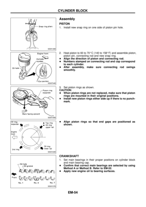
Assembly
PISTON
1. Install new snap ring on one side of piston pin hole.
2. Heat piston to 60 to 70ÉC (140 to 158ÉF) and assemble piston,
piston pin, connecting rod and new snap ring.
+Align the direction of piston and connecting rod.
+Numbers stamped on connecting rod and cap correspond
to each cylinder.
+After assembly, make sure connecting rod swings
smoothly.
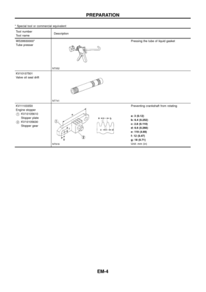
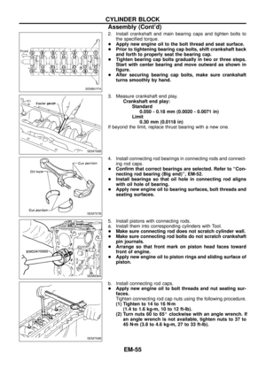
3. Set piston rings as shown.
CAUTION:
+When piston rings are not replaced, make sure that piston
rings are mounted in their original positions.
+Install new piston rings either side up if there is no punch-
mark.
+Align piston rings so that end gaps are positioned as
shown.
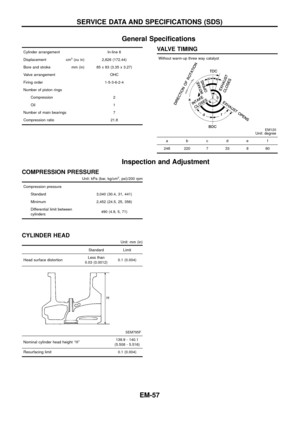
CRANKSHAFT
1. Set main bearings in their proper positions on cylinder block
and main bearing cap.
+Con®rm that correct main bearings are selected by using
Method A or Method B. Refer to EM-52.
+Apply new engine oil to bearing surfaces.
SEM146B
SEM754B
SEM156B
SEM160B
SEM157B
CYLINDER BLOCK
EM-54
Page 56 of 65

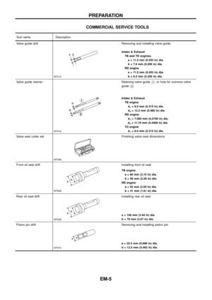
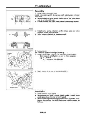
2. Install crankshaft and main bearing caps and tighten bolts to
the speci®ed torque.
+Apply new engine oil to the bolt thread and seat surface.
+Prior to tightening bearing cap bolts, shift crankshaft back
and forth to properly seat the bearing cap.
+Tighten bearing cap bolts gradually in two or three steps.
Start with center bearing and move outward as shown in
®gure.
+After securing bearing cap bolts, make sure crankshaft
turns smoothly by hand.
3. Measure crankshaft end play.
Crankshaft end play:
Standard
0.050 - 0.18 mm (0.0020 - 0.0071 in)
Limit
0.30 mm (0.0118 in)
If beyond the limit, replace thrust bearing with a new one.
4. Install connecting rod bearings in connecting rods and connect-
ing rod caps.
+Con®rm that correct bearings are selected. Refer to ``Con-
necting rod bearing (Big end)'', EM-52.
+Install bearings so that oil hole in connecting rod aligns
with oil hole of bearing.
+Apply new engine oil to bearing surfaces, bolt threads and
seating surfaces.
5. Install pistons with connecting rods.
a. Install them into corresponding cylinders with Tool.
+Make sure connecting rod does not scratch cylinder wall.
+Make sure connecting rod bolts do not scratch crankshaft
pin journals.
+Arrange so that front mark on piston head faces toward
front of engine.
+Apply new engine oil to piston rings and sliding surface of
piston.
b. Install connecting rod caps.
+Apply new engine oil to bolt threads and nut seating sur-
faces.
Tighten connecting rod cap nuts using the following procedure.
(1) Tighten to 14 to 16 Nzm
(1.4 to 1.6 kg-m, 10 to 12 ft-lb).
(2) Turn nuts 60 to 65É clockwise with an angle wrench. If
an angle wrench is not available, tighten nuts to 37 to
45 Nzm (3.8 to 4.6 kg-m, 27 to 33 ft-lb).
SEM801FA
SEM756B
SEM757B
SEM936A
SEM759B
CYLINDER BLOCK
Assembly (Cont'd)
EM-55


:
Main journal
Less than 0.005")
 and assemble piston,
piston pin, connecting rod and new snap ring.
+Align the dir")