Page 25 of 65
Removal and Installation
1. Drain engine coolant.
2. Remove the following:
+Air duct and hoses
+Air intake pipe
+EGR pipe
+Heat shield plates
+Intake manifold
+Front (exhaust) tube
+Oil tube and water tube
3. Remove exhaust manifold with turbocharger from cylinder
head.
4. When installing turbocharger to exhaust manifold, securely
tighten nuts and lock the nuts.
+Turbocharger should not be disassembled.
SEM784F
TURBOCHARGER
EM-24
Page 26 of 65
Inspection
OIL AND WATER TUBES
Check tubes for clogging.
ROTOR SHAFT
1. Check rotor shaft for smooth rotating.
2. Check rotor shaft for carbon deposits.
SEM796C
SEM798C
SEM799C
TURBOCHARGER
EM-25
Page 27 of 65
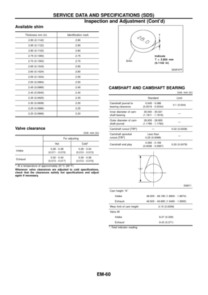
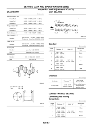
3. Measure runout of rotor shaft.
Runout (Total indicator reading):
0.056 - 0.127 mm (0.0022 - 0.0050 in)
4. Measure end play of rotor shaft.
End play:
0.013 - 0.097 mm (0.0005 - 0.0038 in)
TURBINE WHEEL
Check turbine wheel for the following:
+Oil
+Carbon deposits
+Deformed ®ns
+Contact with turbine housing
COMPRESSOR WHEEL
Check compressor wheel for the following:
+Oil
+Deformed ®ns
+Contact with compressor housing
WASTEGATE VALVE
Remove rod pin and check wastegate valve for cracks, deformation
and smooth movement.
Check valve seat surface for smoothness.
SEM800C
SEM801C
SEM802C
SEM803C
SEM804C
TURBOCHARGER
Inspection (Cont'd)
EM-26
Page 28 of 65
WASTEGATE VALVE ACTUATOR
Apply air pressure to wastegate valve actuator and check it for
smooth movement.
+Do not keep applying air pressure to the actuator.
+The air pressure should be in the range of 108 to 118 kPa
(1.08 to 1.18 bar, 1.1 to 1.2 kg/cm
2, 16 to 17 psi).
SEM805C
TURBOCHARGER
Inspection (Cont'd)
EM-27
Page 29 of 65
SEM791F
CHARGE AIR COOLERS
EM-28
Page 30 of 65
SEM785F
CYLINDER HEAD
EM-29
Page 31 of 65
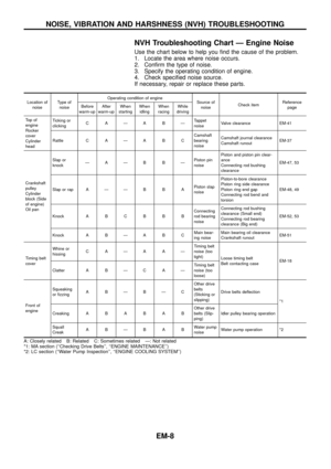
CAUTION:
+When installing sliding parts such as camshaft and oil
seal, be sure to apply new engine oil on their sliding sur-
faces.
+When tightening cylinder head bolts, apply new engine oil
to thread portions and seat surfaces of bolts.
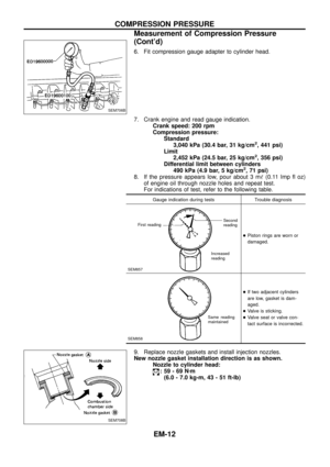
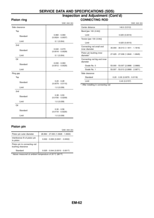
Removal
1. Remove charge air cooler assembly.
2. Set No. 1 cylinder at BDC on its expansion stroke.
3. Drain engine coolant from drain plugs on cylinder block and
radiator.
4. Remove air cleaner and/or air duct.
5. Remove timing belt.
6. Remove rocker cover securing bolts/nuts in numerical order
shown in ®gure.
To install rocker cover, tighten bolts/nuts in reverse order of
removal. Tighten in two or three stages.
7. Remove camshaft sprocket, injection pump drive sprocket and
back cover.
8. Disconnect exhaust manifold from exhaust tube.
9. Remove intake and exhaust manifold.
To install manifolds, tighten bolts/nuts in reverse order of
removal. Tighten in two or three stages.
SEM786F
SEM711B
SEM431C
CYLINDER HEAD
EM-30
Page 32 of 65
10. Remove fuel injection tube assembly and spill tube.
11. Remove cylinder head bolts in numerical order and remove
cylinder head.
Disassembly
1. Remove following parts:
a. Thermostat housing
b. Engine slinger
c. Glow plate and glow plugs
2. Remove camshaft bracket securing nuts in numerical order
shown in ®gure in two or three stages.
To install camshaft bracket caps, tighten nuts in reverse order
of removal. Tighten in two or three stages.
3. Remove camshaft and oil seal.
4. Remove valve lifters.
5. Remove valve component parts with tool.
SEM703B
SEM714B
SEM716B
CYLINDER HEAD
Removal (Cont'd)
EM-31


 tube
+Oil tube and water")

:
0.056 - 0.127 mm (0.0022 - 0.0050 in)
4. Measure end play of rotor shaft.
End play:
0.013 - 0.097 mm (0.0005 - 0.0038 in)
TURBINE WH")


