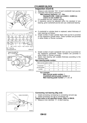
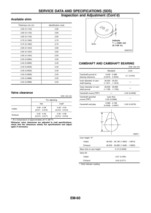
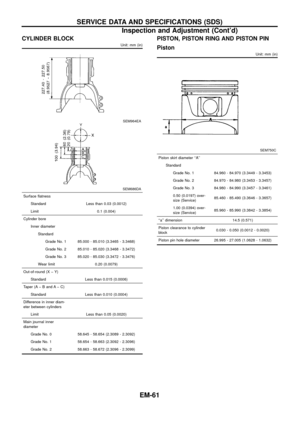
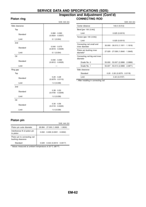
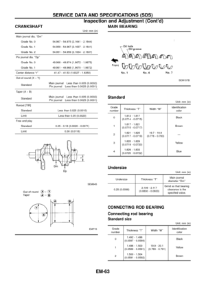
Page 17 of 65
CAUTION:
+Do not bend or twist timing belt.
+After removing timing belt, do not turn crankshaft and
camshaft separately because valves will strike piston
heads.
+Make sure that timing belt, camshaft sprocket, crankshaft
sprocket, idler pulley, injection pump pulley and belt ten-
sioner are clean and free from oil and water.
+Align white lines on timing belt with punch mark on cam-
shaft sprocket, crankshaft sprocket and injection pump
pulley.
+Installation should be carried out when engine is cold.
Removal
1. Remove radiator shroud.
2. Remove the following belts.
+Power steering drive belt
+A/C compressor drive belt
+Alternator drive belt
3. Remove cooling fan coupling and water pump pulley.
SMA767BA
TIMING BELT
EM-16
Page 18 of 65
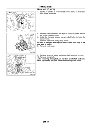
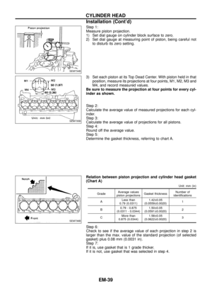
4. Set No. 1 cylinder at bottom dead center (BDC) on its expan-
sion stroke, as shown.
5. Remove the starter motor and wipe off the liquid gasket remain-
ing on the connecting part.
6. Install the ring gear stopper using the bolt holes for ®xing the
starter motor.
7. Remove crankshaft pulley using puller.
Be sure to securely attach puller jaws. Attach jaws only to the
rear side of pulley.
8. Remove front cover.
9. Remove tensioner spring and loosen belt tensioner lock nut.
10. Remove timing belt.
After removing timing belt, do not turn crankshaft and cam-
shaft separately, because valves will strike piston heads.
SMA768B
SMA769B
SMA770B
TIMING BELT
Removal (Cont'd)
EM-17
Page 19 of 65

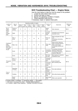
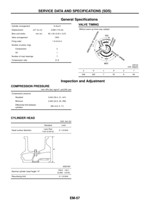
Inspection
Visually check the condition of timing belt.
Replace if any abnormality is found.
Item to check Problem Cause
Tooth is broken/tooth root
is cracked.
SEM394A
+Camshaft jamming
+Distributor jamming
+Damaged camshaft/crankshaft oil seal
Back surface is cracked/
worn.
SEM395A
+Tensioner jamming
+Overheated engine
+Interference with belt cover
Side surface is worn.
+Belt corners are worn and round.
+Wicks are frayed and coming out.
SEM396A
+Improper installation of belt
+Malfunctioning crankshaft pulley plate/timing belt
plate
Teeth are worn.
+Canvas on tooth face is worn down.
+Canvas on tooth is ¯uffy, rubber layer is worn
down and faded white, or weft is worn down and
invisible.
SEM397A
+Poor belt cover sealing
+Coolant leakage at water pump
+Camshaft not functioning properly
+Distributor not functioning properly
+Excessive belt tension
Oil/Coolant or water is
stuck to belt. Ð+Poor oil sealing of each oil seal
+Coolant leakage at water pump
+Poor belt cover sealing
TIMING BELT
EM-18
Page 20 of 65
Installation
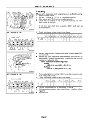
1. Con®rm that No. 1 cylinder is set at BDC on its expansion
stroke as follows:
Con®rm that crankshaft key is at the bottom.
2. Set timing belt.
a. Ensure timing belt, sprockets and pulleys are clean and
free from oil or water. Do not bend or twist timing belt too
much.
b. Align white lines on timing belt with matching mark on
camshaft sprocket, crankshaft sprocket and injection
pump pulley.
c. Point arrow on timing belt toward front.
SMA771B
TIMING BELT
EM-19
Page 21 of 65
3. Install tensioner spring and tighten belt tensioner lock nut.
:32-40Nzm
(3.3 - 4.1 kg-m, 24 - 30 ft-lb)
4. Install front cover.
5. Install crankshaft pulley.
6. Install water pump pulley and cooling fan coupling.
7. Apply liquid gasket to the connecting surface and install the
starter motor.
Use Genuine Liquid Gasket or equivalent.
8. Install drive belts and check drive belt de¯ections by pushing
midway between pulleys.
Refer to MA section (``Checking Drive Belts'').
SMA770B
SMA015C
TIMING BELT
Installation (Cont'd)
EM-20
Page 22 of 65

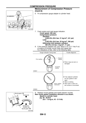
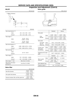
VALVE OIL SEAL
1. Remove timing belts.
2. Remove camshaft sprocket and back covers.
3. Remove camshaft brackets by loosening bracket nuts from
center to outside in two or three stages.
4. Remove camshaft oil seals and camshaft.
5. Remove valve lifters and mark order No. on each lifter.
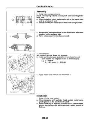
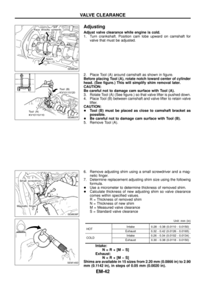
6. Replace valve oil seal according to the following procedure.
When replacing valve oil seal, set the corresponding piston at
TDC. Failure to do so causes the valve to drop into the cylin-
der.
1) Set No. 1 cylinder at TDC.
2) Remove valve springs and valve oil seals for No. 1 and No. 6
cylinders. Valve spring seats should not be removed.
3) Install new valve oil seals for No. 1 and No. 6 cylinders as
illustrated. Reinstall valve springs. (narrow pitch side toward
cylinder head)
4) Install valve spring retainers on intake valves and valve rotators
on exhaust valves, and remount valve assembly.
5) Set No. 2 cylinder at TDC.
6) Replace valve oil seals for No. 2 and No. 5 cylinders according
to steps 2) and 3).
7) Set No. 3 cylinder at TDC.
8) Replace valve oil seals for No. 3 and No. 4 cylinders according
to steps 2) and 3).
9) Install valve lifters in original positions.
SEM716B
SEM790F
SEM745B
SEM746B
OIL SEAL REPLACEMENT
EM-21
Page 23 of 65
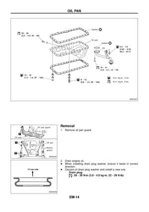
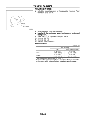
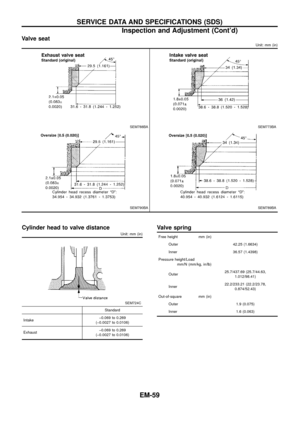
CAMSHAFT AND CRANKSHAFT OIL SEAL INSTALLING
DIRECTION AND MANNER
+When installing camshaft and crankshaft oil seals, be care-
ful to install them correctly, as shown in the ®gure.
+Apply engine oil to oil seal lip, outer face, camshaft and
bracket.
+Wipe off excess oil after installing oil seal.
CAMSHAFT OIL SEALS
1. Remove timing belts, sprockets and back covers.
2. Pull out oil seal with a suitable tool.
3. Install new oil seals with a suitable tool.
CRANKSHAFT FRONT OIL SEAL
1. Remove valve timing belt and crankshaft sprocket.
2. Remove oil pan and oil pan gasket.
3. Remove oil pump assembly.
4. Remove front oil seal with a suitable tool.
5. Apply engine oil to new oil seal and install oil seal using a suit-
able tool.
SEM715A
SEM743B
SEM733B
SEM893A
SEM894A
OIL SEAL REPLACEMENT
EM-22
Page 24 of 65
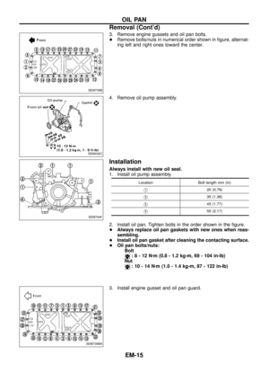
CRANKSHAFT REAR OIL SEAL
1. Remove transmission assembly. (Refer to ``REMOVAL AND
INSTALLATION'' in MT section.)
2. Remove clutch cover assembly.
3. Remove ¯ywheel and rear plate.
4. Remove oil pan and oil pan gasket.
5. Remove oil seal retainer assembly.
6. Remove traces of liquid gasket using a scraper.
7. Remove rear oil seal from retainer.
8. Apply engine oil to new oil seal and install oil seal using a suit-
able tool.
9. Apply a continuous bead of liquid gasket to rear oil seal
retainer.
a. Coat of liquid gasket should be maintained within 2.0 to 3.0
mm (0.079 to 0.118 in) dia. range.
b. Attach oil seal retainer to cylinder block within ®ve min-
utes after coating.
c. Wait at least 30 minutes before re®lling engine oil or start-
ing engine.
d. Use Genuine Liquid Gasket or equivalent.
SEM896A
SEM895A
SEM897A
SLC822
SEM144B
OIL SEAL REPLACEMENT
EM-23


 on its expan-
sion stroke, as shown.
5. Remove the starter motor and wipe off the liquid gasket remain-
ing on the connecting part.
6. Install the rin")


4. Install front cover.
5. Install crankshaft pulley.
6. Install water pump pulley and coolin")


2. Remove clutch cover assembly.
3. Remove ¯ywheel and rear plate.
4. Remove oil pan a")