1998 NISSAN PATROL service
[x] Cancel search: servicePage 1 of 65
ENGINE MECHANICAL
SECTION
EM
CONTENTS
PRECAUTIONS...............................................................1
Parts Requiring Angular Tightening .............................1
Liquid Gasket Application Procedure ..........................1
PREPARATION................................................................2
NOISE, VIBRATION AND HARSHNESS (NVH)
TROUBLESHOOTING.....................................................6
NVH Troubleshooting Chart Ð Engine Noise .............7
OUTER COMPONENT PARTS.......................................8
COMPRESSION PRESSURE........................................10
Measurement of Compression Pressure ...................10
OIL PAN.........................................................................13
Removal .....................................................................13
Installation ..................................................................14
TIMING BELT.................................................................15
Removal .....................................................................15
Inspection...................................................................17
Installation ..................................................................18
OIL SEAL REPLACEMENT..........................................20
TURBOCHARGER.........................................................23
Removal and Installation ...........................................23
Inspection...................................................................24CHARGE AIR COOLERS..............................................27
CYLINDER HEAD..........................................................28
Removal .....................................................................29
Disassembly...............................................................30
Inspection...................................................................31
Assembly ...................................................................37
Installation ..................................................................37
VALVE CLEARANCE....................................................40
Checking ....................................................................40
Adjusting ....................................................................41
ENGINE REMOVAL.......................................................43
Removal .....................................................................44
Installation ..................................................................44
CYLINDER BLOCK.......................................................45
Disassembly...............................................................46
Inspection...................................................................46
Assembly ...................................................................53
SERVICE DATA AND SPECIFICATIONS (SDS)..........56
General Speci®cations ...............................................56
Inspection and Adjustment ........................................56
EM
Page 3 of 65
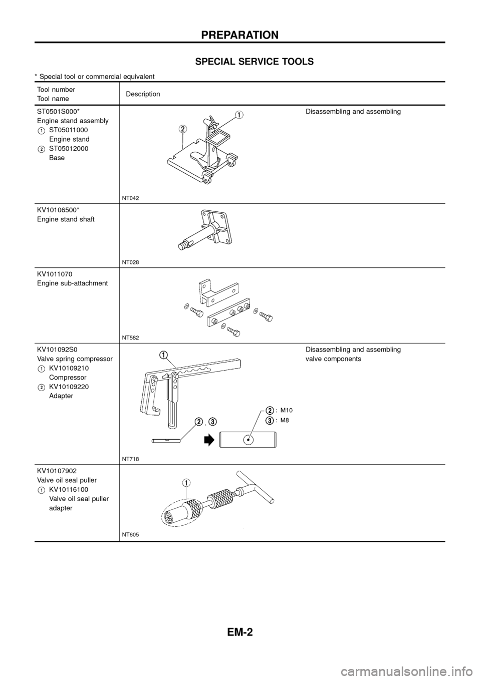
SPECIAL SERVICE TOOLS
* Special tool or commercial equivalent
Tool number
Tool nameDescription
ST0501S000*
Engine stand assembly
V1ST05011000
Engine stand
V2ST05012000
Base
NT042
Disassembling and assembling
KV10106500*
Engine stand shaft
NT028
KV1011070
Engine sub-attachment
NT582
KV101092S0
Valve spring compressor
V1KV10109210
Compressor
V2KV10109220
Adapter
NT718
Disassembling and assembling
valve components
KV10107902
Valve oil seal puller
V1KV10116100
Valve oil seal puller
adapter
NT605
PREPARATION
EM-2
Page 6 of 65
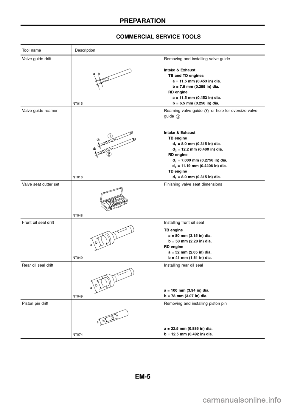
COMMERCIAL SERVICE TOOLS
Tool name Description
Valve guide drift
NT015
Removing and installing valve guide
Intake & Exhaust
TB and TD engines
a = 11.5 mm (0.453 in) dia.
b = 7.6 mm (0.299 in) dia.
RD engine
a = 11.5 mm (0.453 in) dia.
b = 6.5 mm (0.256 in) dia.
Valve guide reamer
NT016
Reaming valve guideV1or hole for oversize valve
guide
V2
Intake & Exhaust
TB engine
d
1= 8.0 mm (0.315 in) dia.
d
2= 12.2 mm (0.480 in) dia.
RD engine
d
1= 7.000 mm (0.2756 in) dia.
d
2= 11.19 mm (0.4406 in) dia.
TD engine
d
1= 8.0 mm (0.315 in) dia.
Valve seat cutter set
NT048
Finishing valve seat dimensions
Front oil seal drift
NT049
Installing front oil seal
TB engine
a = 80 mm (3.15 in) dia.
b = 58 mm (2.28 in) dia.
RD engine
a = 52 mm (2.05 in) dia.
b = 41 mm (1.61 in) dia.
Rear oil seal drift
NT049
Installing rear oil seal
a = 100 mm (3.94 in) dia.
b = 78 mm (3.07 in) dia.
Piston pin drift
NT074
Removing and installing piston pin
a = 22.5 mm (0.886 in) dia.
b = 12.5 mm (0.492 in) dia.
PREPARATION
EM-5
Page 35 of 65
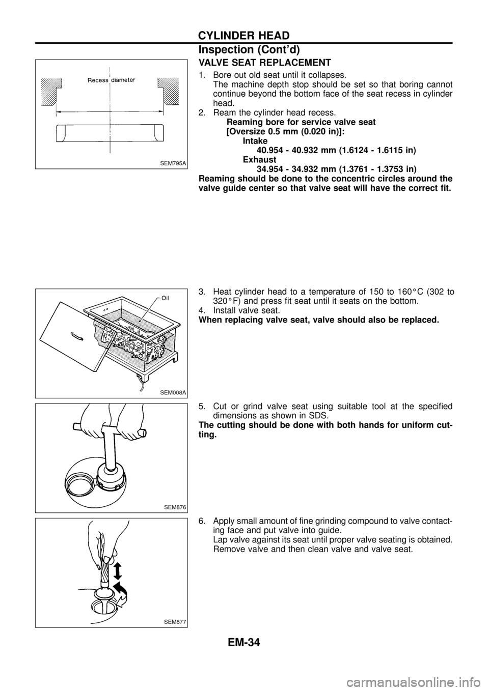
VALVE SEAT REPLACEMENT
1. Bore out old seat until it collapses.
The machine depth stop should be set so that boring cannot
continue beyond the bottom face of the seat recess in cylinder
head.
2. Ream the cylinder head recess.
Reaming bore for service valve seat
[Oversize 0.5 mm (0.020 in)]:
Intake
40.954 - 40.932 mm (1.6124 - 1.6115 in)
Exhaust
34.954 - 34.932 mm (1.3761 - 1.3753 in)
Reaming should be done to the concentric circles around the
valve guide center so that valve seat will have the correct ®t.
3. Heat cylinder head to a temperature of 150 to 160ÉC (302 to
320ÉF) and press ®t seat until it seats on the bottom.
4. Install valve seat.
When replacing valve seat, valve should also be replaced.
5. Cut or grind valve seat using suitable tool at the speci®ed
dimensions as shown in SDS.
The cutting should be done with both hands for uniform cut-
ting.
6. Apply small amount of ®ne grinding compound to valve contact-
ing face and put valve into guide.
Lap valve against its seat until proper valve seating is obtained.
Remove valve and then clean valve and valve seat.
SEM795A
SEM008A
SEM876
SEM877
CYLINDER HEAD
Inspection (Cont'd)
EM-34
Page 51 of 65
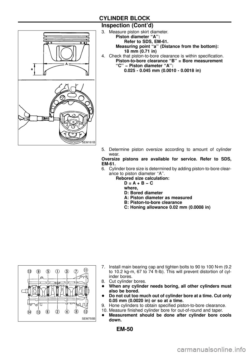
3. Measure piston skirt diameter.
Piston diameter ``A'':
Refer to SDS, EM-61.
Measuring point ``a'' (Distance from the bottom):
18 mm (0.71 in)
4. Check that piston-to-bore clearance is within speci®cation.
Piston-to-bore clearance ``B'' = Bore measurement
``C'' þ Piston diameter ``A'':
0.025 - 0.045 mm (0.0010 - 0.0018 in)
5. Determine piston oversize according to amount of cylinder
wear.
Oversize pistons are available for service. Refer to SDS,
EM-61.
6. Cylinder bore size is determined by adding piston-to-bore clear-
ance to piston diameter ``A''.
Rebored size calculation:
D=A+BþC
where,
D: Bored diameter
A: Piston diameter as measured
B: Piston-to-bore clearance
C: Honing allowance 0.02 mm (0.0008 in)
7. Install main bearing cap and tighten bolts to 90 to 100 Nzm (9.2
to 10.2 kg-m, 67 to 74 ft-lb). This will prevent distortion of cyl-
inder bores.
8. Cut cylinder bores.
+When any cylinder needs boring, all other cylinders must
also be bored.
+Do not cut too much out of cylinder bore at a time. Cut only
0.05 mm (0.0020 in) or so at a time.
9. Hone cylinders to obtain speci®ed piston-to-bore clearance.
10. Measure ®nished cylinder bore for out-of-round and taper.
+Measurement should be done after cylinder bore cools
down.
SEM181B
SEM755B
CYLINDER BLOCK
Inspection (Cont'd)
EM-50
Page 58 of 65
General Speci®cations
Cylinder arrangement In-line 6
Displacement cm
3(cu in) 2,826 (172.44)
Bore and stroke mm (in) 85 x 83 (3.35 x 3.27)
Valve arrangement OHC
Firing order 1-5-3-6-2-4
Number of piston rings
Compression 2
Oil 1
Number of main bearings 7
Compression ratio 21.8
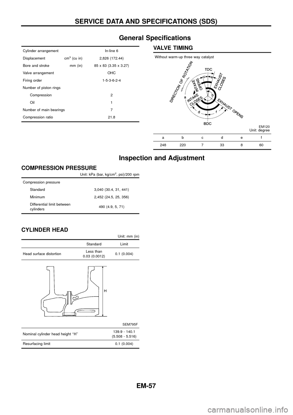
VALVE TIMING
Without warm-up three way catalyst
EM120Unit: degree
abcde f
248 220 7 33 8 60
Inspection and Adjustment
COMPRESSION PRESSURE
Unit: kPa (bar, kg/cm2, psi)/200 rpm
Compression pressure
Standard 3,040 (30.4, 31, 441)
Minimum 2,452 (24.5, 25, 356)
Differential limit between
cylinders490 (4.9, 5, 71)
CYLINDER HEAD
Unit: mm (in)
Standard Limit
Head surface distortionLess than
0.03 (0.0012)0.1 (0.004)
SEM795F
Nominal cylinder head height ``H''139.9 - 140.1
(5.508 - 5.516)
Resurfacing limit 0.1 (0.004)
SERVICE DATA AND SPECIFICATIONS (SDS)
EM-57
Page 59 of 65
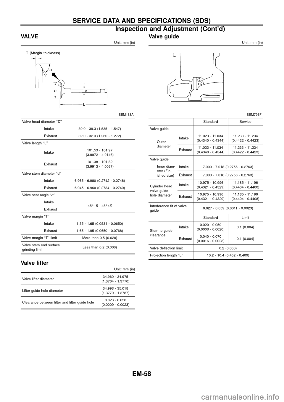
VA LV E
Unit: mm (in)
SEM188A
Valve head diameter ``D''
Intake 39.0 - 39.3 (1.535 - 1.547)
Exhaust 32.0 - 32.3 (1.260 - 1.272)
Valve length ``L''
Intake101.53 - 101.97
(3.9972 - 4.0146)
Exhaust101.38 - 101.82
(3.9913 - 4.0087)
Valve stem diameter ``d''
Intake 6.965 - 6.980 (0.2742 - 0.2748)
Exhaust 6.945 - 6.960 (0.2734 - 0.2740)
Valve seat angle ``a''
Intake
45É15¢- 45É45¢
Exhaust
Valve margin ``T''
Intake 1.35 - 1.65 (0.0531 - 0.0650)
Exhaust 1.65 - 1.95 (0.0650 - 0.0768)
Valve margin ``T'' limit More than 0.5 (0.020)
Valve stem end surface
grinding limitLess than 0.2 (0.008)
Valve lifter
Unit: mm (in)
Valve lifter diameter34.960 - 34.975
(1.3764 - 1.3770)
Lifter guide hole diameter34.998 - 35.018
(1.3779 - 1.3787)
Clearance between lifter and lifter guide hole0.023 - 0.058
(0.0009 - 0.0023)
Valve guide
Unit: mm (in)
SEM796F
Standard Service
Valve guide
Outer
diameterIntake11.023 - 11.034
(0.4340 - 0.4344)11.233 - 11.234
(0.4422 - 0.4423)
Exhaust11.023 - 11.034
(0.4340 - 0.4344)11.233 - 11.234
(0.4422 - 0.4423)
Valve guide
Inner diam-
eter (Fin-
ished size)Intake 7.000 - 7.018 (0.2756 - 0.2763)
Exhaust 7.000 - 7.018 (0.2756 - 0.2763)
Cylinder head
valve guide
hole diameterIntake10.975 - 10.996
(0.4321 - 0.4329)11.185 - 11.196
(0.4404 - 0.4408)
Exhaust10.975 - 10.996
(0.4321 - 0.4329)11.185 - 11.196
(0.4404 - 0.4408)
Interference ®t of valve
guide0.027 - 0.059 (0.0011 - 0.0023)
Standard Limit
Stem to guide
clearanceIntake0.020 - 0.050
(0.0008 - 0.0020)0.1 (0.004)
Exhaust0.040 - 0.070
(0.0016 - 0.0028)0.1 (0.004)
Valve de¯ection limit 0.2 (0.008)
Projection length ``L'' 10.2 - 10.4 (0.402 - 0.409)
SERVICE DATA AND SPECIFICATIONS (SDS)
Inspection and Adjustment (Cont'd)
EM-58
Page 60 of 65
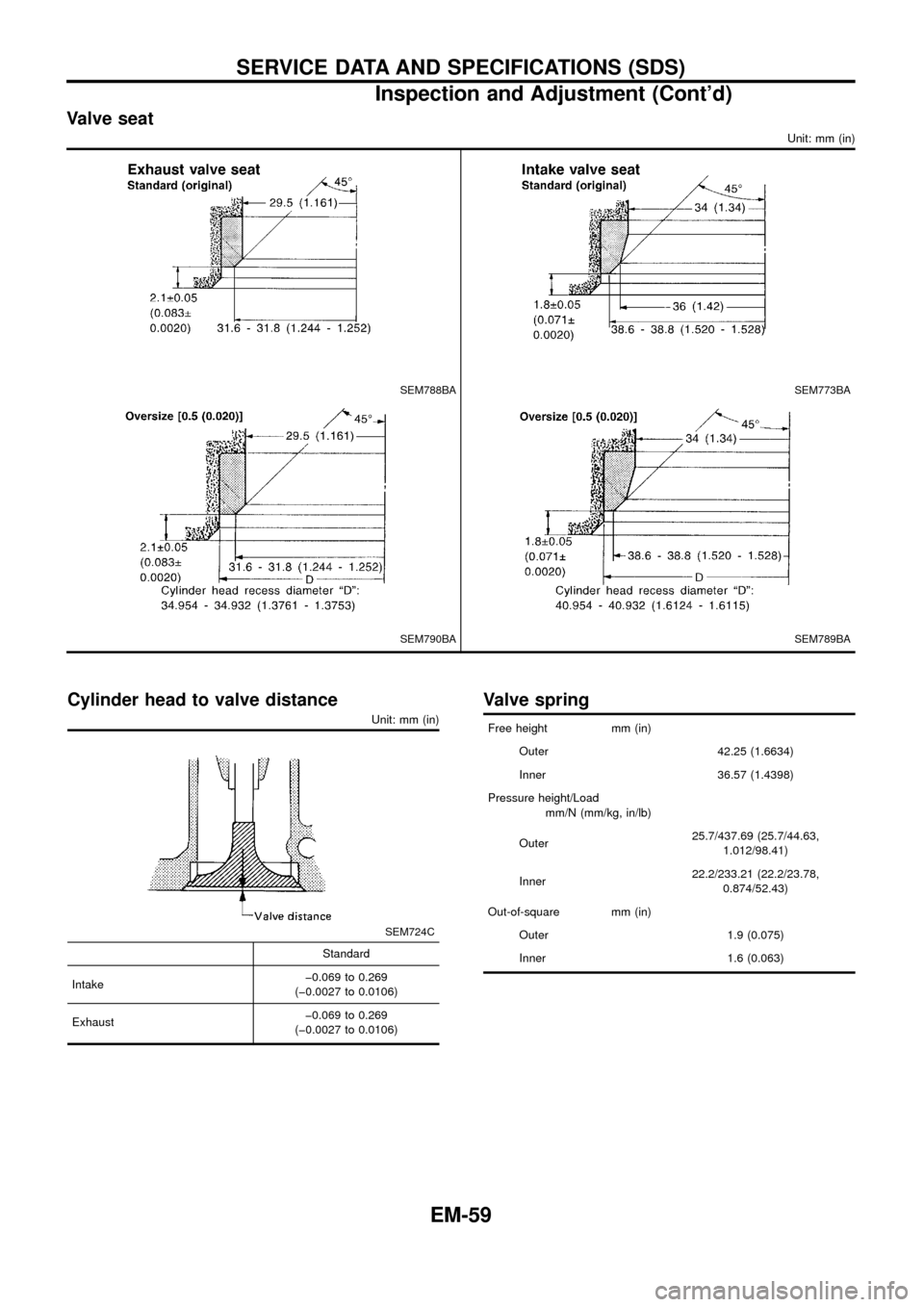
Valve seat
Unit: mm (in)
SEM788BASEM773BA
SEM790BASEM789BA
Cylinder head to valve distance
Unit: mm (in)
SEM724C
Standard
Intakeþ0.069 to 0.269
(þ0.0027 to 0.0106)
Exhaustþ0.069 to 0.269
(þ0.0027 to 0.0106)
Valve spring
Free height mm (in)
Outer 42.25 (1.6634)
Inner 36.57 (1.4398)
Pressure height/Load
mm/N (mm/kg, in/lb)
Outer25.7/437.69 (25.7/44.63,
1.012/98.41)
Inner22.2/233.21 (22.2/23.78,
0.874/52.43)
Out-of-square mm (in)
Outer 1.9 (0.075)
Inner 1.6 (0.063)
SERVICE DATA AND SPECIFICATIONS (SDS)
Inspection and Adjustment (Cont'd)
EM-59