Page 33 of 65

Inspection
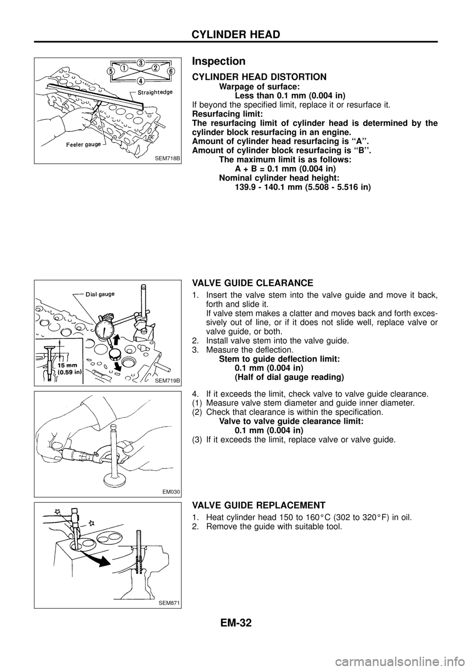
CYLINDER HEAD DISTORTION
Warpage of surface:
Less than 0.1 mm (0.004 in)
If beyond the speci®ed limit, replace it or resurface it.
Resurfacing limit:
The resurfacing limit of cylinder head is determined by the
cylinder block resurfacing in an engine.
Amount of cylinder head resurfacing is ``A''.
Amount of cylinder block resurfacing is ``B''.
The maximum limit is as follows:
A + B = 0.1 mm (0.004 in)
Nominal cylinder head height:
139.9 - 140.1 mm (5.508 - 5.516 in)
VALVE GUIDE CLEARANCE
1. Insert the valve stem into the valve guide and move it back,
forth and slide it.
If valve stem makes a clatter and moves back and forth exces-
sively out of line, or if it does not slide well, replace valve or
valve guide, or both.
2. Install valve stem into the valve guide.
3. Measure the de¯ection.
Stem to guide de¯ection limit:
0.1 mm (0.004 in)
(Half of dial gauge reading)
4. If it exceeds the limit, check valve to valve guide clearance.
(1) Measure valve stem diameter and guide inner diameter.
(2) Check that clearance is within the speci®cation.
Valve to valve guide clearance limit:
0.1 mm (0.004 in)
(3) If it exceeds the limit, replace valve or valve guide.
VALVE GUIDE REPLACEMENT
1. Heat cylinder head 150 to 160ÉC (302 to 320ÉF) in oil.
2. Remove the guide with suitable tool.
SEM718B
SEM719B
EM030
SEM871
CYLINDER HEAD
EM-32
Page 38 of 65

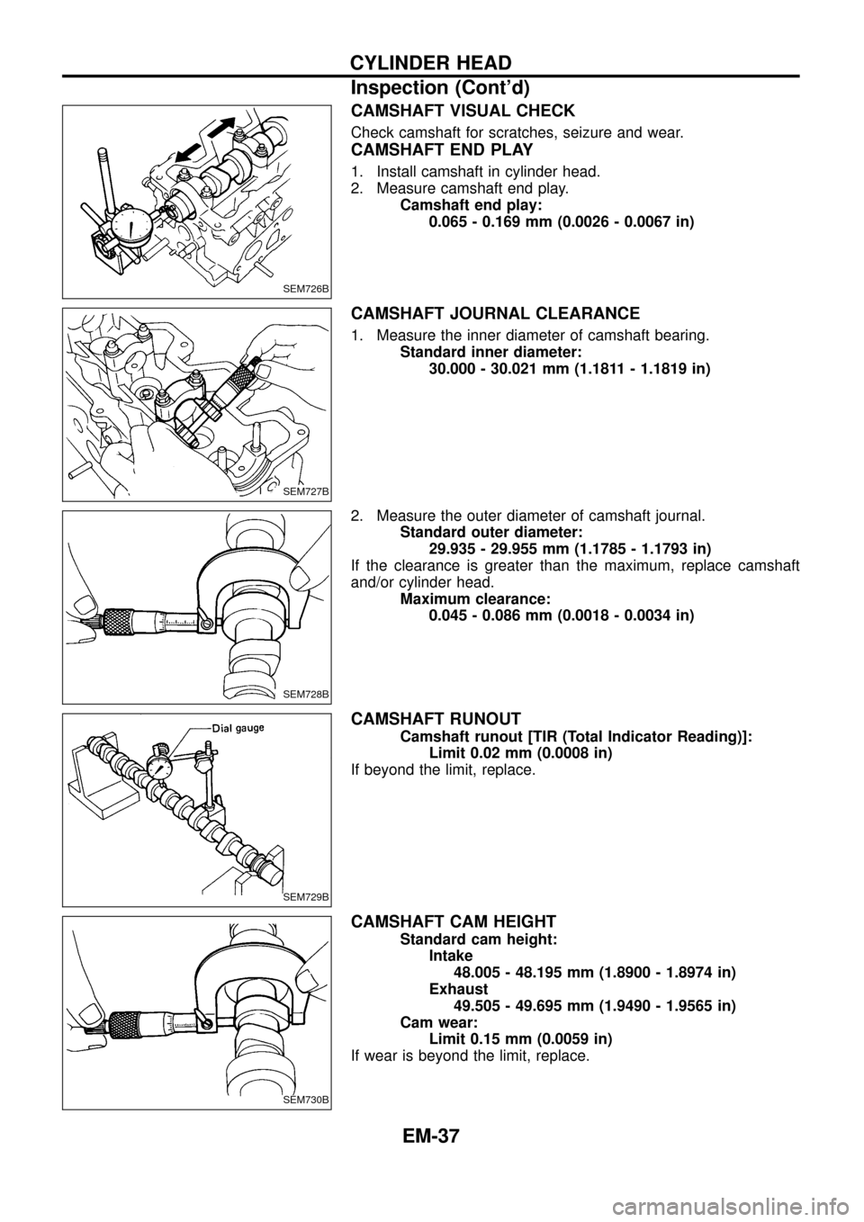
CAMSHAFT VISUAL CHECK
Check camshaft for scratches, seizure and wear.
CAMSHAFT END PLAY
1. Install camshaft in cylinder head.
2. Measure camshaft end play.
Camshaft end play:
0.065 - 0.169 mm (0.0026 - 0.0067 in)
CAMSHAFT JOURNAL CLEARANCE
1. Measure the inner diameter of camshaft bearing.
Standard inner diameter:
30.000 - 30.021 mm (1.1811 - 1.1819 in)
2. Measure the outer diameter of camshaft journal.
Standard outer diameter:
29.935 - 29.955 mm (1.1785 - 1.1793 in)
If the clearance is greater than the maximum, replace camshaft
and/or cylinder head.
Maximum clearance:
0.045 - 0.086 mm (0.0018 - 0.0034 in)
CAMSHAFT RUNOUT
Camshaft runout [TIR (Total Indicator Reading)]:
Limit 0.02 mm (0.0008 in)
If beyond the limit, replace.
CAMSHAFT CAM HEIGHT
Standard cam height:
Intake
48.005 - 48.195 mm (1.8900 - 1.8974 in)
Exhaust
49.505 - 49.695 mm (1.9490 - 1.9565 in)
Cam wear:
Limit 0.15 mm (0.0059 in)
If wear is beyond the limit, replace.
SEM726B
SEM727B
SEM728B
SEM729B
SEM730B
CYLINDER HEAD
Inspection (Cont'd)
EM-37
Page 50 of 65

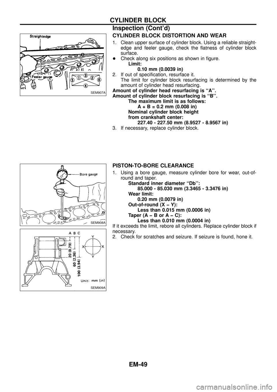
CYLINDER BLOCK DISTORTION AND WEAR
1. Clean upper surface of cylinder block. Using a reliable straight-
edge and feeler gauge, check the ¯atness of cylinder block
surface.
+Check along six positions as shown in ®gure.
Limit:
0.10 mm (0.0039 in)
2. If out of speci®cation, resurface it.
The limit for cylinder block resurfacing is determined by the
amount of cylinder head resurfacing.
Amount of cylinder head resurfacing is ``A''.
Amount of cylinder block resurfacing is ``B''.
The maximum limit is as follows:
A + B = 0.2 mm (0.008 in)
Nominal cylinder block height
from crankshaft center:
227.40 - 227.50 mm (8.9527 - 8.9567 in)
3. If necessary, replace cylinder block.
PISTON-TO-BORE CLEARANCE
1. Using a bore gauge, measure cylinder bore for wear, out-of-
round and taper.
Standard inner diameter ``Db'':
85.000 - 85.030 mm (3.3465 - 3.3476 in)
Wear limit:
0.20 mm (0.0079 in)
Out-of-round (X þ Y):
Less than 0.015 mm (0.0006 in)
Taper (A þ B or A þ C):
Less than 0.010 mm (0.0004 in)
If it exceeds the limit, rebore all cylinders. Replace cylinder block if
necessary.
2. Check for scratches and seizure. If seizure is found, hone it.
SEM907A
SEM908A
SEM909A
CYLINDER BLOCK
Inspection (Cont'd)
EM-49
Page 58 of 65
General Speci®cations
Cylinder arrangement In-line 6
Displacement cm
3(cu in) 2,826 (172.44)
Bore and stroke mm (in) 85 x 83 (3.35 x 3.27)
Valve arrangement OHC
Firing order 1-5-3-6-2-4
Number of piston rings
Compression 2
Oil 1
Number of main bearings 7
Compression ratio 21.8
VALVE TIMING
Without warm-up three way catalyst
EM120Unit: degree
abcde f
248 220 7 33 8 60
Inspection and Adjustment
COMPRESSION PRESSURE
Unit: kPa (bar, kg/cm2, psi)/200 rpm
Compression pressure
Standard 3,040 (30.4, 31, 441)
Minimum 2,452 (24.5, 25, 356)
Differential limit between
cylinders490 (4.9, 5, 71)
CYLINDER HEAD
Unit: mm (in)
Standard Limit
Head surface distortionLess than
0.03 (0.0012)0.1 (0.004)
SEM795F
Nominal cylinder head height ``H''139.9 - 140.1
(5.508 - 5.516)
Resurfacing limit 0.1 (0.004)
SERVICE DATA AND SPECIFICATIONS (SDS)
EM-57
Page 60 of 65
Valve seat
Unit: mm (in)
SEM788BASEM773BA
SEM790BASEM789BA
Cylinder head to valve distance
Unit: mm (in)
SEM724C
Standard
Intakeþ0.069 to 0.269
(þ0.0027 to 0.0106)
Exhaustþ0.069 to 0.269
(þ0.0027 to 0.0106)
Valve spring
Free height mm (in)
Outer 42.25 (1.6634)
Inner 36.57 (1.4398)
Pressure height/Load
mm/N (mm/kg, in/lb)
Outer25.7/437.69 (25.7/44.63,
1.012/98.41)
Inner22.2/233.21 (22.2/23.78,
0.874/52.43)
Out-of-square mm (in)
Outer 1.9 (0.075)
Inner 1.6 (0.063)
SERVICE DATA AND SPECIFICATIONS (SDS)
Inspection and Adjustment (Cont'd)
EM-59
Page 61 of 65

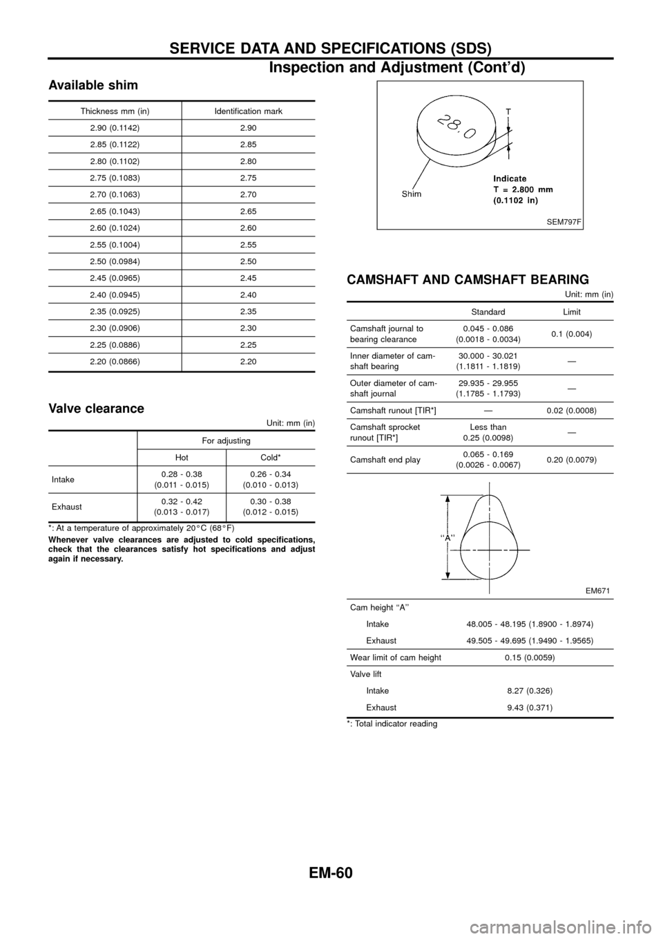
Available shim
Thickness mm (in) Identi®cation mark
2.90 (0.1142) 2.90
2.85 (0.1122) 2.85
2.80 (0.1102) 2.80
2.75 (0.1083) 2.75
2.70 (0.1063) 2.70
2.65 (0.1043) 2.65
2.60 (0.1024) 2.60
2.55 (0.1004) 2.55
2.50 (0.0984) 2.50
2.45 (0.0965) 2.45
2.40 (0.0945) 2.40
2.35 (0.0925) 2.35
2.30 (0.0906) 2.30
2.25 (0.0886) 2.25
2.20 (0.0866) 2.20
Valve clearance
Unit: mm (in)
For adjusting
Hot Cold*
Intake0.28 - 0.38
(0.011 - 0.015)0.26 - 0.34
(0.010 - 0.013)
Exhaust0.32 - 0.42
(0.013 - 0.017)0.30 - 0.38
(0.012 - 0.015)
*: At a temperature of approximately 20ÉC (68ÉF)
Whenever valve clearances are adjusted to cold speci®cations,
check that the clearances satisfy hot speci®cations and adjust
again if necessary.
CAMSHAFT AND CAMSHAFT BEARING
Unit: mm (in)
Standard Limit
Camshaft journal to
bearing clearance0.045 - 0.086
(0.0018 - 0.0034)0.1 (0.004)
Inner diameter of cam-
shaft bearing30.000 - 30.021
(1.1811 - 1.1819)Ð
Outer diameter of cam-
shaft journal29.935 - 29.955
(1.1785 - 1.1793)Ð
Camshaft runout [TIR*] Ð 0.02 (0.0008)
Camshaft sprocket
runout [TIR*]Less than
0.25 (0.0098)Ð
Camshaft end play0.065 - 0.169
(0.0026 - 0.0067)0.20 (0.0079)
EM671
Cam height ``A''
Intake 48.005 - 48.195 (1.8900 - 1.8974)
Exhaust 49.505 - 49.695 (1.9490 - 1.9565)
Wear limit of cam height 0.15 (0.0059)
Valve lift
Intake 8.27 (0.326)
Exhaust 9.43 (0.371)
*: Total indicator reading
SEM797F
SERVICE DATA AND SPECIFICATIONS (SDS)
Inspection and Adjustment (Cont'd)
EM-60