Page 24 of 65
CRANKSHAFT REAR OIL SEAL
1. Remove transmission assembly. (Refer to ``REMOVAL AND
INSTALLATION'' in MT section.)
2. Remove clutch cover assembly.
3. Remove ¯ywheel and rear plate.
4. Remove oil pan and oil pan gasket.
5. Remove oil seal retainer assembly.
6. Remove traces of liquid gasket using a scraper.
7. Remove rear oil seal from retainer.
8. Apply engine oil to new oil seal and install oil seal using a suit-
able tool.
9. Apply a continuous bead of liquid gasket to rear oil seal
retainer.
a. Coat of liquid gasket should be maintained within 2.0 to 3.0
mm (0.079 to 0.118 in) dia. range.
b. Attach oil seal retainer to cylinder block within ®ve min-
utes after coating.
c. Wait at least 30 minutes before re®lling engine oil or start-
ing engine.
d. Use Genuine Liquid Gasket or equivalent.
SEM896A
SEM895A
SEM897A
SLC822
SEM144B
OIL SEAL REPLACEMENT
EM-23
Page 27 of 65
3. Measure runout of rotor shaft.
Runout (Total indicator reading):
0.056 - 0.127 mm (0.0022 - 0.0050 in)
4. Measure end play of rotor shaft.
End play:
0.013 - 0.097 mm (0.0005 - 0.0038 in)
TURBINE WHEEL
Check turbine wheel for the following:
+Oil
+Carbon deposits
+Deformed ®ns
+Contact with turbine housing
COMPRESSOR WHEEL
Check compressor wheel for the following:
+Oil
+Deformed ®ns
+Contact with compressor housing
WASTEGATE VALVE
Remove rod pin and check wastegate valve for cracks, deformation
and smooth movement.
Check valve seat surface for smoothness.
SEM800C
SEM801C
SEM802C
SEM803C
SEM804C
TURBOCHARGER
Inspection (Cont'd)
EM-26
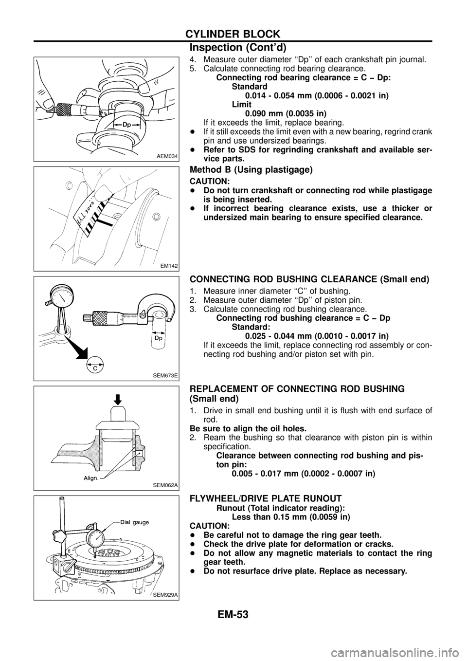
Page 54 of 65

4. Measure outer diameter ``Dp'' of each crankshaft pin journal.
5. Calculate connecting rod bearing clearance.
Connecting rod bearing clearance=CþDp:
Standard
0.014 - 0.054 mm (0.0006 - 0.0021 in)
Limit
0.090 mm (0.0035 in)
If it exceeds the limit, replace bearing.
+If it still exceeds the limit even with a new bearing, regrind crank
pin and use undersized bearings.
+Refer to SDS for regrinding crankshaft and available ser-
vice parts.
Method B (Using plastigage)
CAUTION:
+Do not turn crankshaft or connecting rod while plastigage
is being inserted.
+If incorrect bearing clearance exists, use a thicker or
undersized main bearing to ensure speci®ed clearance.
CONNECTING ROD BUSHING CLEARANCE (Small end)
1. Measure inner diameter ``C'' of bushing.
2. Measure outer diameter ``Dp'' of piston pin.
3. Calculate connecting rod bushing clearance.
Connecting rod bushing clearance=CþDp
Standard:
0.025 - 0.044 mm (0.0010 - 0.0017 in)
If it exceeds the limit, replace connecting rod assembly or con-
necting rod bushing and/or piston set with pin.
REPLACEMENT OF CONNECTING ROD BUSHING
(Small end)
1. Drive in small end bushing until it is ¯ush with end surface of
rod.
Be sure to align the oil holes.
2. Ream the bushing so that clearance with piston pin is within
speci®cation.
Clearance between connecting rod bushing and pis-
ton pin:
0.005 - 0.017 mm (0.0002 - 0.0007 in)
FLYWHEEL/DRIVE PLATE RUNOUT
Runout (Total indicator reading):
Less than 0.15 mm (0.0059 in)
CAUTION:
+Be careful not to damage the ring gear teeth.
+Check the drive plate for deformation or cracks.
+Do not allow any magnetic materials to contact the ring
gear teeth.
+Do not resurface drive plate. Replace as necessary.
AEM034
EM142
SEM673E
SEM062A
SEM929A
CYLINDER BLOCK
Inspection (Cont'd)
EM-53
Page 65 of 65
Undersize
Unit: mm (in)
Undersize Thickness ``T''Crank pin journal
diameter ``Dp''
0.08 (0.0031)1.536 - 1.540
(0.0605 - 0.0606)
Grind so that bearing
clearance is the
speci®ed value. 0.12 (0.0047)1.556 - 1.560
(0.0613 - 0.0614)
0.25 (0.0098)1.621 - 1.625
(0.0638 - 0.0640)
Bearing clearance
Unit: mm (in)
Main bearing clearance
Standard 0.036 - 0.063 (0.0014 - 0.0025)
Limit 0.12 (0.0047)
Connecting rod bearing clearance
Standard 0.031 - 0.055 (0.0012 - 0.0022)
Limit 0.11 (0.0043)
MISCELLANEOUS COMPONENTS
Unit: mm (in)
Camshaft sprocket runout limit
[TIR]0.1 (0.004)
Flywheel runout limit [TIR] 0.1 (0.004)
Drive plate runout limit [TIR] 0.1 (0.004)
SERVICE DATA AND SPECIFICATIONS (SDS)
Inspection and Adjustment (Cont'd)
EM-64