Page 31 of 65
CAUTION:
+When installing sliding parts such as camshaft and oil
seal, be sure to apply new engine oil on their sliding sur-
faces.
+When tightening cylinder head bolts, apply new engine oil
to thread portions and seat surfaces of bolts.
Removal
1. Remove charge air cooler assembly.
2. Set No. 1 cylinder at BDC on its expansion stroke.
3. Drain engine coolant from drain plugs on cylinder block and
radiator.
4. Remove air cleaner and/or air duct.
5. Remove timing belt.
6. Remove rocker cover securing bolts/nuts in numerical order
shown in ®gure.
To install rocker cover, tighten bolts/nuts in reverse order of
removal. Tighten in two or three stages.
7. Remove camshaft sprocket, injection pump drive sprocket and
back cover.
8. Disconnect exhaust manifold from exhaust tube.
9. Remove intake and exhaust manifold.
To install manifolds, tighten bolts/nuts in reverse order of
removal. Tighten in two or three stages.
SEM786F
SEM711B
SEM431C
CYLINDER HEAD
EM-30
Page 46 of 65
Removal
1. Remove engine, transmission and transfer's undercovers, oil
pan guard and hood.
2. Drain engine coolant.
3. Remove charge air cooler assembly.
4. Remove vacuum hoses, fuel tubes, harnesses, and connectors
and so on.
5. Remove radiator assembly.
6. Remove drive belts.
7. Remove power steering oil pump, alternator and air conditioner
compressor.
8. Remove starter motor assembly.
9. Remove front exhaust tube.
10. Remove transmission from vehicle.
Refer to MT section.
11. Hoist engine with engine slingers and remove engine mounting
bolts from both sides.
12. Remove engine from vehicle.
Installation
+Install in reverse order of removal.
ENGINE REMOVAL
EM-45
Page 48 of 65

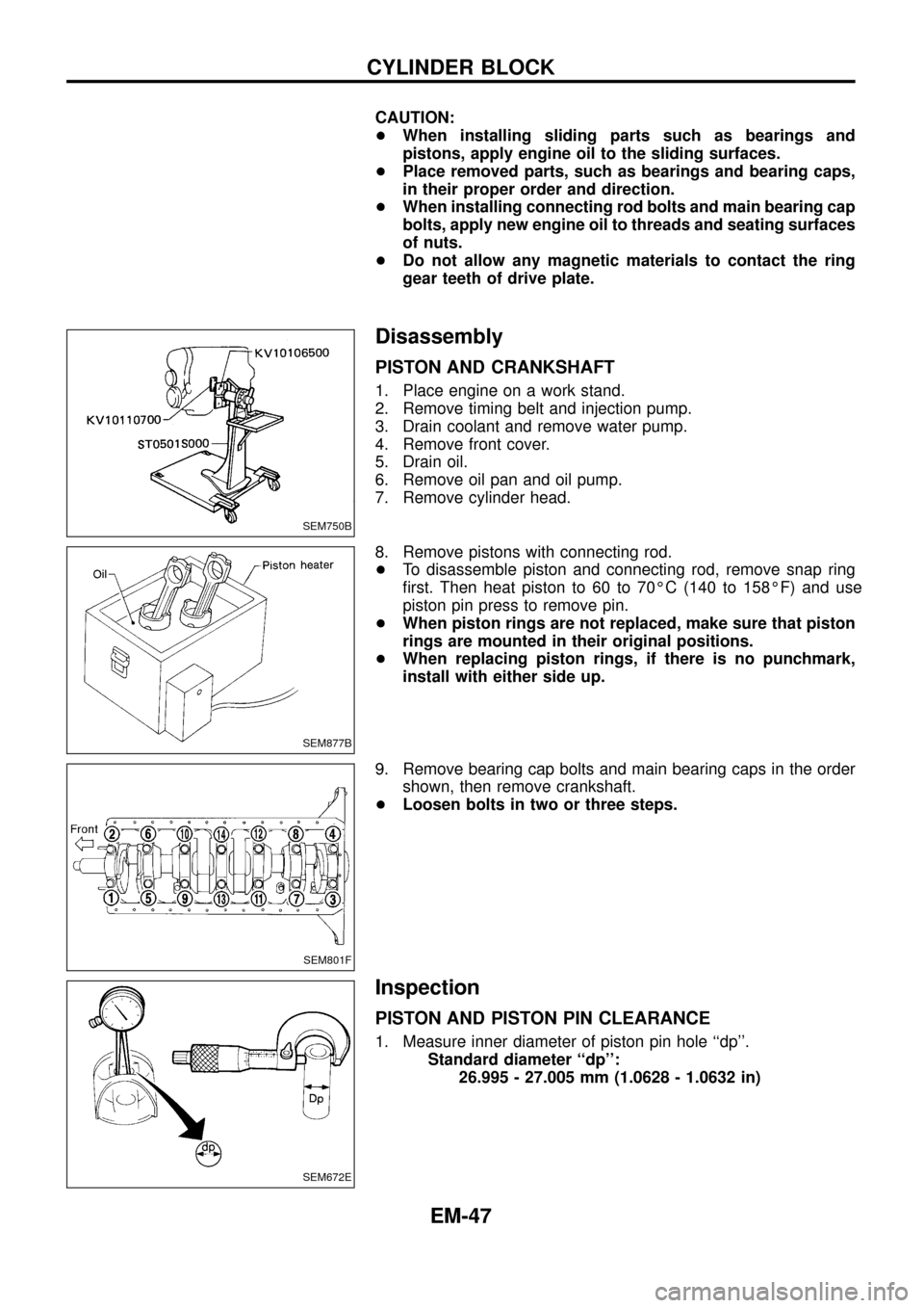
CAUTION:
+When installing sliding parts such as bearings and
pistons, apply engine oil to the sliding surfaces.
+Place removed parts, such as bearings and bearing caps,
in their proper order and direction.
+When installing connecting rod bolts and main bearing cap
bolts, apply new engine oil to threads and seating surfaces
of nuts.
+Do not allow any magnetic materials to contact the ring
gear teeth of drive plate.
Disassembly
PISTON AND CRANKSHAFT
1. Place engine on a work stand.
2. Remove timing belt and injection pump.
3. Drain coolant and remove water pump.
4. Remove front cover.
5. Drain oil.
6. Remove oil pan and oil pump.
7. Remove cylinder head.
8. Remove pistons with connecting rod.
+To disassemble piston and connecting rod, remove snap ring
®rst. Then heat piston to 60 to 70ÉC (140 to 158ÉF) and use
piston pin press to remove pin.
+When piston rings are not replaced, make sure that piston
rings are mounted in their original positions.
+When replacing piston rings, if there is no punchmark,
install with either side up.
9. Remove bearing cap bolts and main bearing caps in the order
shown, then remove crankshaft.
+Loosen bolts in two or three steps.
Inspection
PISTON AND PISTON PIN CLEARANCE
1. Measure inner diameter of piston pin hole ``dp''.
Standard diameter ``dp'':
26.995 - 27.005 mm (1.0628 - 1.0632 in)
SEM750B
SEM877B
SEM801F
SEM672E
CYLINDER BLOCK
EM-47