Page 41 of 65
 Make sure that No. 1 cylinder is at Bottom Dead Center.
(2) Make sure that No. 1 cam of camshaft is at BDC on its expan-
sion stroke.
(3) Tighten cylinder head bolts to t")
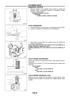
2. Install cylinder head.
(1) Make sure that No. 1 cylinder is at Bottom Dead Center.
(2) Make sure that No. 1 cam of camshaft is at BDC on its expan-
sion stroke.
(3) Tighten cylinder head bolts to the speci®ed torque in the
sequence as follows:
+Tightening procedure.
M12 bolt
1st Tighten all bolts to 29 Nzm (3.0 kg-m, 22 ft-lb).
2nd Tighten all bolts to 113 Nzm (11.5 kg-m, 83 ft-lb).
3rd Loosen all bolts completely.
4th Tighten all bolts to 29 Nzm (3.0 kg-m, 22 ft-lb).
5th Tighten all bolts to 108 to 118 Nzm (11 to 12 kg-m, 80 to
87 ft-lb) or if you have an angle wrench, turn all bolts 89
to 92 degrees clockwise.
M8 bolt
16-21Nzm (1.6 - 2.1 kg-m, 12 - 15 ft-lb)
3. Install front back cover and camshaft pulley.
Front back cover:
:3-5Nzm
(0.3 - 0.5 kg-m, 26 - 43 in-lb)
Camshaft pulley:
: 123 - 132 Nzm
(12.5 - 13.5 kg-m, 90 - 98 ft-lb)
4. Install timing belt. Refer to ``Replacing Timing Belt'' in section
MA.
5. Install rocker cover. Refer to EM-30.
Apply sealant to rocker cover gasket as shown.
Do not apply too much sealant.
6. Install intake and exhaust manifold. Refer to EM-30.
SEM732B
SEM737BA
SEM711B
SEM738B
CYLINDER HEAD
Installation (Cont'd)
EM-40
Page 42 of 65

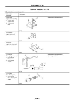
Checking
Check valve clearance while engine is warm and not running.
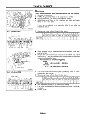
1. Remove rocker cover.
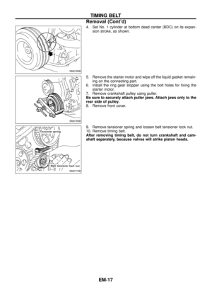
2. Set No. 1 cylinder at TDC on its compression stroke.
+Align pointer with TDC mark on crankshaft pulley.
+Check that valve lifters on No. 1 cylinder are loose and valve
lifters on No. 6 are tight.
If not, turn crankshaft one revolution (360É) and align as
described above.
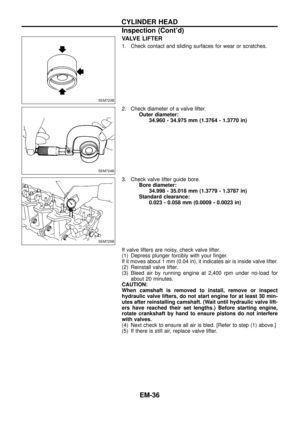
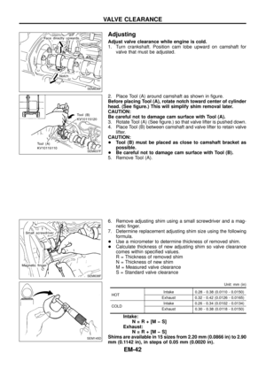
3. Check only those valves shown in the ®gure.
No. 1 No. 2 No. 3 No. 4 No. 5 No. 6
INT EXH INT EXH INT EXH INT EXH INT EXH INT EXH
No. 1 cylin-
der at TDCjjj jj j
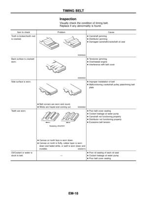
+Using a feeler gauge, measure clearance between valve lifter
and camshaft.
+Record any valve clearance measurements which are out of
speci®cation. They will be used later to determine the required
replacement adjusting shim.
Valve clearance for checking (Hot):
Intake
0.28 - 0.38 mm (0.011 - 0.015 in)
Exhaust
0.32 - 0.42 mm (0.013 - 0.017 in)
4. Turn crankshaft one revolution (360É) and align mark on crank-
shaft pulley with pointer.
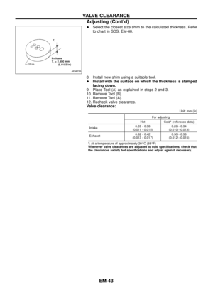
5. Check only those valves shown in the ®gure.
No. 1 No. 2 No. 3 No. 4 No. 5 No. 6
INT EXH INT EXH INT EXH INT EXH INT EXH INT EXH
No. 6 cylin-
der at TDCjj jj jj
+Use the same procedure as mentioned in step 4.
6. If all valve clearances are within speci®cation, install the follow-
ing parts:
+Rocker cover
SEM790F
SEM799F
SEM634F
SEM800F
VALVE CLEARANCE
EM-41
Page 43 of 65
 around camshaft as shown in ®gure.
B")
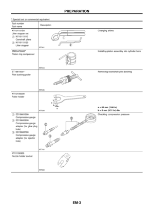
Adjusting
Adjust valve clearance while engine is cold.
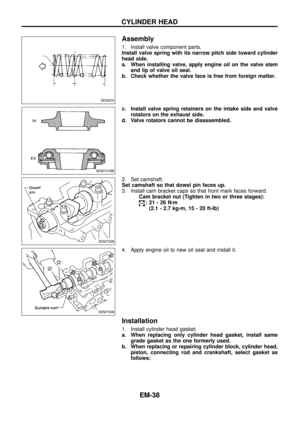
1. Turn crankshaft. Position cam lobe upward on camshaft for
valve that must be adjusted.
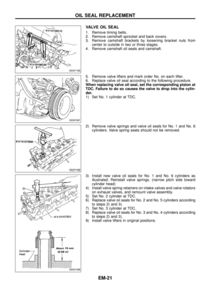
2. Place Tool (A) around camshaft as shown in ®gure.
Before placing Tool (A), rotate notch toward center of cylinder
head. (See ®gure.) This will simplify shim removal later.
CAUTION:
Be careful not to damage cam surface with Tool (A).
3. Rotate Tool (A) (See ®gure.) so that valve lifter is pushed down.
4. Place Tool (B) between camshaft and valve lifter to retain valve
lifter.
CAUTION:
+Tool (B) must be placed as close to camshaft bracket as
possible.
+Be careful not to damage cam surface with Tool (B).
5. Remove Tool (A).
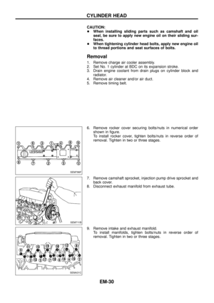
6. Remove adjusting shim using a small screwdriver and a mag-
netic ®nger.
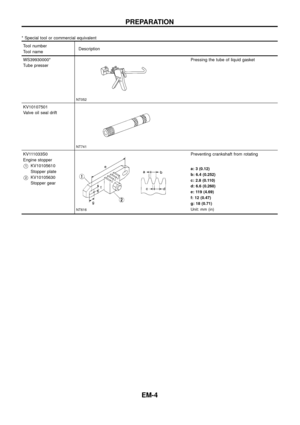
7. Determine replacement adjusting shim size using the following
formula.
+Use a micrometer to determine thickness of removed shim.
+Calculate thickness of new adjusting shim so valve clearance
comes within speci®ed values.
R = Thickness of removed shim
N = Thickness of new shim
M = Measured valve clearance
S = Standard valve clearance
Unit: mm (in)
HOTIntake 0.28 - 0.38 (0.0110 - 0.0150)
Exhaust 0.32 - 0.42 (0.0126 - 0.0165)
COLDIntake 0.26 - 0.34 (0.0102 - 0.0134)
Exhaust 0.30 - 0.38 (0.0118 - 0.0150)
Intake:
N=R+[MþS]
Exhaust:
N=R+[MþS]
Shims are available in 15 sizes from 2.20 mm (0.0866 in) to 2.90
mm (0.1142 in), in steps of 0.05 mm (0.0020 in).
SEM636F
SEM637F
SEM638F
SEM145D
VALVE CLEARANCE
EM-42
Page 44 of 65
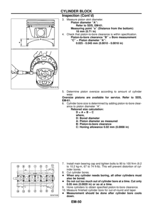
+Select the closest size shim to the calculated thickness. Refer
to chart in SDS, EM-60.
8. Install new shim using a suitable tool.
+Install with the surface on which the thickness is stamped
facing down.
9. Place Tool (A) as explained in steps 2 and 3.
10. Remove Tool (B).
11. Remove Tool (A).
12. Recheck valve clearance.
Valve clearance:
Unit: mm (in)
For adjusting
Hot Cold* (reference data)
Intake0.28 - 0.38
(0.011 - 0.015)0.26 - 0.34
(0.010 - 0.013)
Exhaust0.32 - 0.42
(0.013 - 0.017)0.30 - 0.38
(0.012 - 0.015)
*: At a temperature of approximately 20ÉC (68ÉF)
Whenever valve clearances are adjusted to cold speci®cations, check that
the clearances satisfy hot speci®cations and adjust again if necessary.
AEM236
VALVE CLEARANCE
Adjusting (Cont'd)
EM-43
Page 45 of 65
SEM433C
ENGINE REMOVAL
EM-44
Page 46 of 65
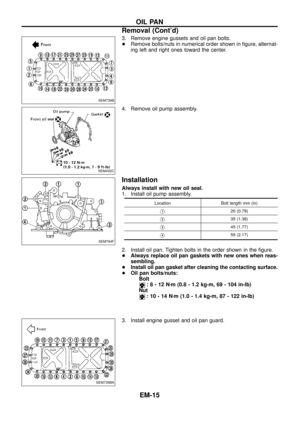
Removal
1. Remove engine, transmission and transfer's undercovers, oil
pan guard and hood.
2. Drain engine coolant.
3. Remove charge air cooler assembly.
4. Remove vacuum hoses, fuel tubes, harnesses, and connectors
and so on.
5. Remove radiator assembly.
6. Remove drive belts.
7. Remove power steering oil pump, alternator and air conditioner
compressor.
8. Remove starter motor assembly.
9. Remove front exhaust tube.
10. Remove transmission from vehicle.
Refer to MT section.
11. Hoist engine with engine slingers and remove engine mounting
bolts from both sides.
12. Remove engine from vehicle.
Installation
+Install in reverse order of removal.
ENGINE REMOVAL
EM-45
Page 47 of 65
SEM788F
CYLINDER BLOCK
EM-46
Page 48 of 65

CAUTION:
+When installing sliding parts such as bearings and
pistons, apply engine oil to the sliding surfaces.
+Place removed parts, such as bearings and bearing caps,
in their proper order and direction.
+When installing connecting rod bolts and main bearing cap
bolts, apply new engine oil to threads and seating surfaces
of nuts.
+Do not allow any magnetic materials to contact the ring
gear teeth of drive plate.
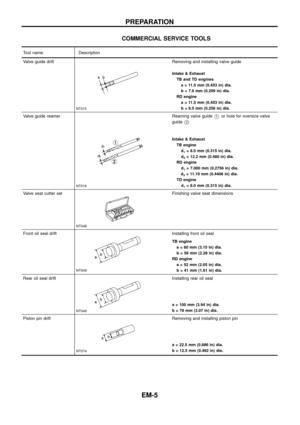
Disassembly
PISTON AND CRANKSHAFT
1. Place engine on a work stand.
2. Remove timing belt and injection pump.
3. Drain coolant and remove water pump.
4. Remove front cover.
5. Drain oil.
6. Remove oil pan and oil pump.
7. Remove cylinder head.
8. Remove pistons with connecting rod.
+To disassemble piston and connecting rod, remove snap ring
®rst. Then heat piston to 60 to 70ÉC (140 to 158ÉF) and use
piston pin press to remove pin.
+When piston rings are not replaced, make sure that piston
rings are mounted in their original positions.
+When replacing piston rings, if there is no punchmark,
install with either side up.
9. Remove bearing cap bolts and main bearing caps in the order
shown, then remove crankshaft.
+Loosen bolts in two or three steps.
Inspection
PISTON AND PISTON PIN CLEARANCE
1. Measure inner diameter of piston pin hole ``dp''.
Standard diameter ``dp'':
26.995 - 27.005 mm (1.0628 - 1.0632 in)
SEM750B
SEM877B
SEM801F
SEM672E
CYLINDER BLOCK
EM-47