Page 9 of 65

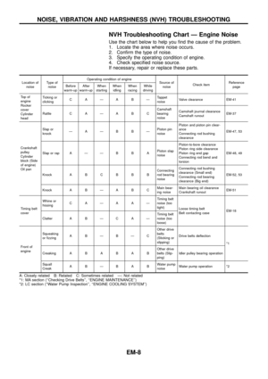
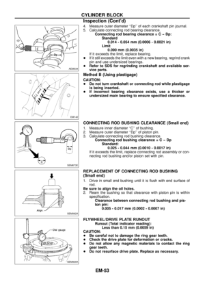
NVH Troubleshooting Chart Ð Engine Noise
Use the chart below to help you ®nd the cause of the problem.
1. Locate the area where noise occurs.
2. Con®rm the type of noise.
3. Specify the operating condition of engine.
4. Check speci®ed noise source.
If necessary, repair or replace these parts.
Location of
noiseType of
noiseOperating condition of engine
Source of
noiseCheck itemReference
page Before
warm-upAfter
warm-upWhen
startingWhen
idlingWhen
racingWhile
driving
To p o f
engine
Rocker
cover
Cylinder
headTicking or
clickingCAÐABÐTappet
noiseValve clearance EM-41
Rattle C A Ð A B CCamshaft
bearing
noiseCamshaft journal clearance
Camshaft runoutEM-37
Crankshaft
pulley
Cylinder
block (Side
of engine)
Oil panSlap or
knockÐAÐB BÐPiston pin
noisePiston and piston pin clear-
ance
Connecting rod bushing
clearanceEM-47, 53
Slap or rap A Ð Ð B B APiston slap
noisePiston-to-bore clearance
Piston ring side clearance
Piston ring end gap
Connecting rod bend and
torsionEM-48, 49
Knock A B C B B BConnecting
rod bearing
noiseConnecting rod bushing
clearance (Small end)
Connecting rod bearing
clearance (Big end)EM-52, 53
Knock A B Ð A B CMain bear-
ing noiseMain bearing oil clearance
Crankshaft runoutEM-51
Timing belt
coverWhine or
hissingCAÐAAÐTiming belt
noise (too
tight)
Loose timing belt
Belt contacting caseEM-18
Clatter A B Ð C A ÐTiming belt
noise (too
loose)
Front of
engineSqueaking
or ®zzingABÐBÐCOther drive
belts
(Sticking or
slipping)Drive belts de¯ection
*1
CreakingABABABOther drive
belts (Slip-
ping)Idler pulley bearing operation
Squall
CreakABÐBABWater pump
noiseWater pump operation *2
A: Closely related B: Related C: Sometimes related Ð: Not related
*1: MA section (``Checking Drive Belts'', ``ENGINE MAINTENANCE'')
*2: LC section (``Water Pump Inspection'', ``ENGINE COOLING SYSTEM'')
NOISE, VIBRATION AND HARSHNESS (NVH) TROUBLESHOOTING
EM-8
Page 10 of 65
SEM780F
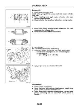
OUTER COMPONENT PARTS
EM-9
Page 11 of 65
SEM781F
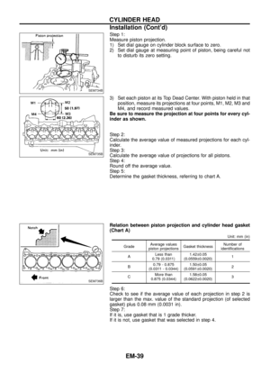
OUTER COMPONENT PARTS
EM-10
Page 12 of 65
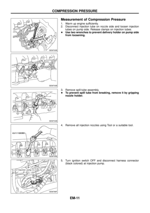
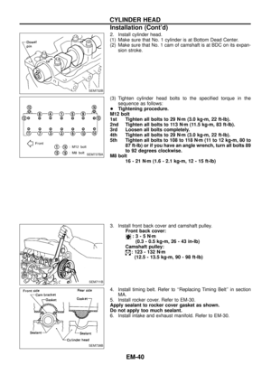
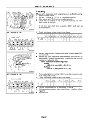
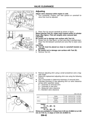
Measurement of Compression Pressure
1. Warm up engine sufficiently.
2. Disconnect injection tube on nozzle side and loosen injection
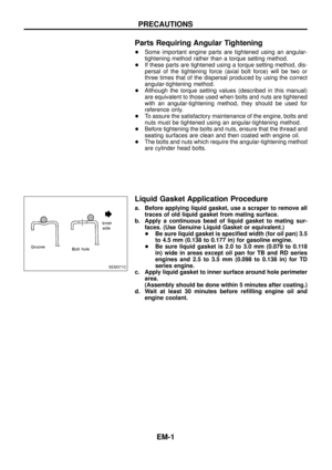
tubes on pump side. Release clamps on injection tubes.
+Use two wrenches to prevent delivery holder on pump side
from loosening.
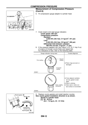
3. Remove spill-tube assembly.
+To prevent spill tube from breaking, remove it by gripping
nozzle holder.
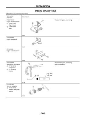
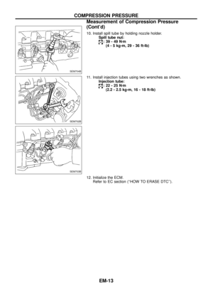
4. Remove all injection nozzles using Tool or a suitable tool.
5. Turn ignition switch OFF and disconnect harness connector
(black colored) at injection pump.
SEM702B
SEM703B
SEM704B
SEM705B
SEM789F
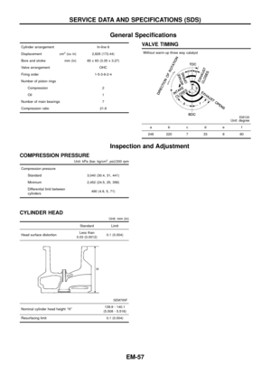
COMPRESSION PRESSURE
EM-11
Page 13 of 65

Limit
2,452")
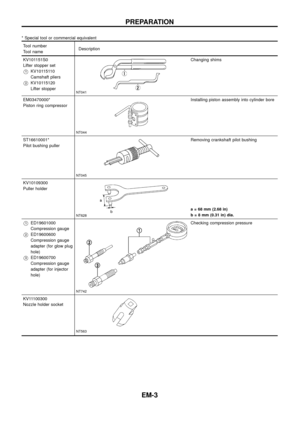
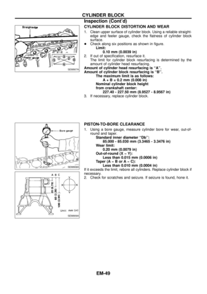
6. Fit compression gauge adapter to cylinder head.
7. Crank engine and read gauge indication.
Crank speed: 200 rpm
Compression pressure:
Standard
3,040 kPa (30.4 bar, 31 kg/cm
2, 441 psi)
Limit
2,452 kPa (24.5 bar, 25 kg/cm
2, 356 psi)
Differential limit between cylinders
490 kPa (4.9 bar, 5 kg/cm
2, 71 psi)
8. If the pressure appears low, pour about 3 m!(0.11 Imp ¯ oz)
of engine oil through nozzle holes and repeat test.
For indications of test, refer to the following table.
Gauge indication during tests Trouble diagnosis
SEM857
+Piston rings are worn or
damaged.
SEM858
+If two adjacent cylinders
are low, gasket is dam-
aged.
+Valve is sticking.
+Valve seat or valve con-
tact surface is incorrected.
9. Replace nozzle gaskets and install injection nozzles.
New nozzle gasket installation direction is as shown.
Nozzle to cylinder head:
:59-69Nzm
(6.0 - 7.0 kg-m, 43 - 51 ft-lb)
SEM706B
SEM708B
COMPRESSION PRESSURE
Measurement of Compression Pressure
(Cont'd)
EM-12
First readingSecond
reading
Increased
reading
Same reading
maintained
Page 14 of 65
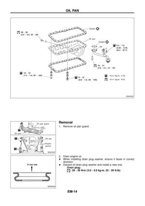
10. Install spill tube by holding nozzle holder.
Spill tube nut:
:39-49Nzm
(4 - 5 kg-m, 29 - 36 ft-lb)
11. Install injection tubes using two wrenches as shown.
Injection tube:
:22-25Nzm
(2.2 - 2.5 kg-m, 16 - 18 ft-lb)
12. Initialize the ECM.
Refer to EC section (``HOW TO ERASE DTC'').
SEM704B
SEM702B
SEM703B
COMPRESSION PRESSURE
Measurement of Compression Pressure
(Cont'd)
EM-13
Page 15 of 65
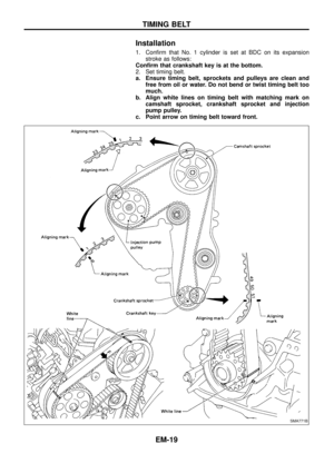
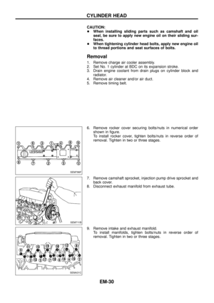
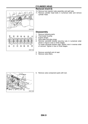
Removal
1. Remove oil pan guard.
2. Drain engine oil.
+When installing drain plug washer, ensure it faces in correct
direction.
+Discard oil drain plug washer and install a new one.
Drain plug:
:29-39Nzm (3.0 - 4.0 kg-m, 22 - 29 ft-lb)
SEM782F
SEM783F
SEM063B
OIL PAN
EM-14
Page 16 of 65
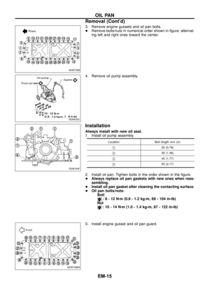
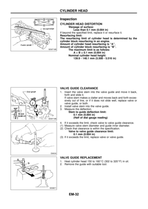
3. Remove engine gussets and oil pan bolts.
+Remove bolts/nuts in numerical order shown in ®gure, alternat-
ing left and right ones toward the center.
4. Remove oil pump assembly.
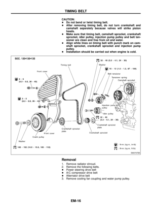
Installation
Always install with new oil seal.
1. Install oil pump assembly.
Location Bolt length mm (in)
V120 (0.79)
V235 (1.38)
V345 (1.77)
V455 (2.17)
2. Install oil pan. Tighten bolts in the order shown in the ®gure.
+Always replace oil pan gaskets with new ones when reas-
sembling.
+Install oil pan gasket after cleaning the contacting surface.
+Oil pan bolts/nuts:
Bolt
:8-12Nzm (0.8 - 1.2 kg-m, 69 - 104 in-lb)
Nut
:10-14Nzm (1.0 - 1.4 kg-m, 87 - 122 in-lb)
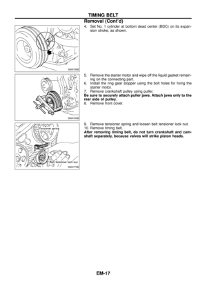
3. Install engine gusset and oil pan guard.
SEM739B
SEM432C
SEM794F
SEM739BA
OIL PAN
Removal (Cont'd)
EM-15


11. Install injection tubes using two wrenches as shown.
Injection tube:
:22-25Nzm
(2.2 - 2.5 kg-")

