Page 41 of 230

TROUBLE DIAGNOSES
Symptom Matrix Chart (Cont'd)
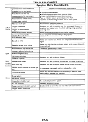
Engine mechanical-related malfunction I Symptom characteristics and inspection hints
Airffuel
ratio becomes lean.
Air sucked in at oil filler cap
Aidfuel ratio compensation factor becomes higher.
a Intake manifold induction vacuum becomes lower.
I Cracked intake manifold I
Misconnection of canister piping Use an induction vacuum (pressure) gauge for check.
' Common to all air sucking conditions from air intake system.
-
PCV valve stuck open
I Malfunctioning pressure regulator I Various symptoms occur depending on the fuel pressure.
Abnormal noise (peep) may
be heard.
Air/fuel
mixture
Improper gasoline properties Various
symptoms occur depending on the properties.
IEGRiale
stuck open
I
Clogged fuel strainer .
Clogged air cleaner element
Deposits on valve
r
Symptoms vary with the condition how they are clogged. However, the
symptoms tend to occur when the vehicle is driving at high speed and
under high load.
I
Air/fuel ratio becomes lean. Airfluel ratio compensation factor becomes
higher.
Excessive canister purge volume
I
Engine may stall when the accelerator pedal is lightly pressed. (Especially
in summertime.)
Misconnection of high-tension wire Check if the ignition timing
is correct. 1 Improperly adjusted ignition timing 1
Malfunctioning spark plug 1
Corn- I Improper valve contact I Symptoms vary with the degree of contact and the number of cylinders. '
High-tension wire leaks
Distributor
cap leaks Symptoms
vary with the degree of leaks.
Clogged catalytic converter or exhaust sys-
l tem , In many cases, engine stalls and then restarts after a while. I
pression I
Low base idle speed
pressure
Worn piston ring I
Engine may
stall while the vehicle is decelerating or when the power '
steering load or electrical load is applied.
Symptoms vary
with the degree of wear and the number of cylinders.
I
Air conditioner load too heavy I Too much refrigerant in the system. j
Others Dragging
brake
Belt tension too high
1
I Clogged radiator or capacitor I
ArJ load too heavy
Foreign material (vinyl, etc.) in fuel tank Insufficient A/T fluid (FR model)
Symptom tends to occur when fuel level in the tank becomes lower.
Page 42 of 230

TROUBLE DIAGNOSES
ldle speed adjusting screw
ECL1641 C
ldle Speed Inspection and Adjustment
ldle speed specification (After warm-up)
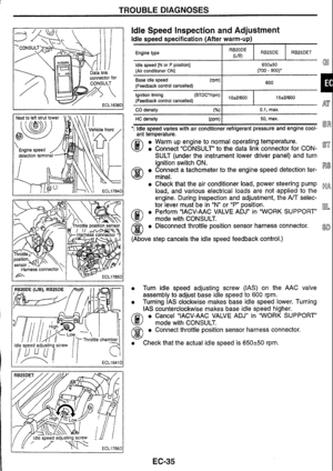
Engine type I RygE I RB25DE I RB25DET
Base idle speed (Pm)
(Feedback control cancelled) 600
I 1
idle speed [N or P position] (Air conditioner ON)
Ignition timing
(Feedback control cancelled) I 15*2/600
. . I I
650250 Go (700 - 900)'
CO density 0.1, max.
HC density 50, max.
': ldle speed varies with air conditioner refrigerant pressure and engine cool- "" "
ant temperature.
0
a Warm up engine to normal operating temperature.
a Connect "CONSULT' to the data link connector for CON- 87'
SULT (under the instrument lower driver panel) and turn
ignition switch ON.
Connect a tachometer to the engine speed detection ter- R8
minal.
a Check that the air conditioner load, power steering pump ~p, -4 load, and various electrical loads are not applied to the
engine. During inspection and adjustment, the
A/T selec-
tor lever must be in
"N"
or
"P"
position.
a Perform "IACV-AAC VALVE ADJn in "WORK SUPPORT EL
@ mode with CONSULS.
@ a Disconnect throttle position sensor harness connector. 8~
(Above step cancels the idle speed feedback control.)
0 Turn idle speed adjusting screw (IAS) on the AAC valve
assembly to adjust base idle speed to
600 rpm.
a Turning IAS clockwise makes base idle speed lower. Turning
IAS counterclockwise makes base idle speed higher.
a Cancel "IACV-AAC VALVE ADJ" in "WORK SUPPORT'
@ mode with CONSULT.
a Connect throttle position sensor harness connector.
a Check that the actual idle speed is 650-1-50 rpm.
Page 43 of 230

TROUBLE DlAGNOSES
Ignition Timing inspection and Adjustment
lnstall a timing light to the ignition timing detection loop (blue)
A3 e Perform "IACV-AAC VALVE ADJ" in "WORK SUPPORT
mode with CONSULT.
/Ci3 Disconnect throttle position sensor harness connector.
w (Above step cancels the idle speed and ignition timing feedbacl
cont rots.)
Cancel "IACV-AAC VALVE ADJ" in "WORK SUPPORl
@ mode with CONSULT.
Connect throttle position sensor harness connector.
Race engine and check that the ignition timing advana
immediately.
With the engine idling, check that the ignition timing and bas1
idle speed is within the specification listed below.
If not within the specifications, loosen the crankshaft positio
sensor mounting bolt, turn the crankshaft position sensor
an
adjust the ignition timing to the specifications. Turning th
crankshaft position sensor counterclockwise advances th
ignition timing.
Unit: BTDCO/rpl
CAUTION:
When idle speed or ignition timing is checked and adjuste
with the throttle position sensor harness
connectc
disconnected, the self-diagnostic results of the throttle
COI
trol unit and the ABS must be erased. To erase the self-dia!
nostic
results, first turn ignition switch OFF, and then start tt
engine. Confirm that the
TCS OFF indicator lamp, 4WD indic
tor lamp, and
ABS indicator lamp are all OFF, then erase tt
self-diagnostic results. This must be done because disco
nection
of the throttle position sensor harness connectc
even for engine adjustment,
will make control units to dete
abnormal status.
RB25DE, RB25DET
15*2/600 Engine type
Ignition timing
RB20DE (VB)
1 O-e2/600
Page 44 of 230

TROUBLE DIAGNOSES
AirIFuel Ratio Inspection
Insert probe into left exhaust pipe.
ECLl788D
L Malfunction indicator lamp
CO/HC DENSITY INSPECTION
The vehicle uses aidfuel ratio feedback system with learning func-
tion. Because wide range of compensation is available, no
CO/HC
density adjustment is necessary. G!
Warm up engine to normal operating temperature, and check
that the idle speed and the ignition timing are within the speci-
fications. Then, check
CO/HC density with COIHC meter.
CAUTION:
muffler. Therefore, insert probe of the COMC meter into the
I
RB25DET-NT model uses exhaust pressure-sensitive control
I left exhaust pipe. (under -no-load condition, exhaust gas is
emitted from the left exhaust pipe only.)
a If not within the specifications, check the airlfuel ratio feedback
@status as follows.
Select "MIR FIC MNT" in "DATA MONITOR" mode.
a Run engine at approx. 2,000 rpm or higher and check that ST
I "RICH" and "LEAN" are displayed alternately.
Turn ignition switch ON and connect terminals CHK and Rs
@ IGN on the data link connector for CONSULT (under
instrument lower driver panel) for
2 seconds or more with
a suitable harness, then disconnect them. klk~
a Warm up the engine to normal operating temperature, then run
the engine at 2,000
rpm or higher. Check that the malfunction
indicator lamp blinks at least five times in
10 seconds. La=
0 Engine speed should be increased (approx. 2,000 rpm)
before performing check, even though the
air/fuel ratio
feedback control is active during idling.
8D
Page 45 of 230

TROUBLE DIAGNOSES
Fuel Pressure Inspection
Fuel pump fuse
Pressure hose
QUICK
INSPECTION
0 Turn ignition switch ON (engine not running).
Select "FUEL PUMP CIRCUIT' in "FUNCTION TEST
mode.
Pinch fuel hose with fingers and check for pulsation.
Pinch fuel hose between fuel filter and fuel gallery (fue
@ damper for RB2SDET model) with fingers while fuel puml
is operating. Hose should feel hard or pulsating.
INSPECTION USING FUEL PRESSURE GAUGE
Releasing fuel pressure
Start engine.
Select "FUEL PRESSURE RELEASE" in "WORK SUP
PORT' mode.
Touch "START' and after engine stalls, crank it two o
three times to release all fuel pressure.
Start engine and disconnect fuel pump fuse.
After engine stalls, crank it two or three times to releas
all fuel pressure.
Installing fuel pressure gauge
Connect a fuel pressure gauge between fuel filter and fue
gallery (fuel damper for
RB25DET model).
CAUTION:
When disconnecting fuel hose, use shop cloth to remove an!
fuel leaks.
Install fuel pump fuse.
Fuel pressure standard value confirmation
Start engine and check that the fuel pressure is as specified.
Fuel pressure [MPa (kg/cm2)]
At idle: 0.25 (2.5)
When vacuum hose is disconnected from pres-
sure regulator:
0.29 (3.0)
If the vehicle shows poor starting, check fuel pressure fo
approx.
5 seconds after ignition switch is turned ON (During :
sec. after ignition switch turned ON for RB25DET model).
Fuel pressure [MPa (kg/cm2)]
During 5 sec. after ignition switch turned ON:
0.29 (3.0)
When fuel pressure is NG
Too high: Malfunctioning pressure regulator, malfunction in^
fuel damper, clogged fuel return line, bent hose
Too low: Malfunctioning pressure regulator, malfunctioning fue
damper, poor fuel pump discharging, clogged fuel supply line
clogged fuel filter
CAUTION:
Also check fuel pressure at increased engine speed.
Page 46 of 230

TROUBLE DIAGNOSES
P ECM (aTCM) InputDutput Signal Reference
Value
SIGNAL VOLTAGES MEASURED WITH OSCILLOSCOPE AND CIRCUIT TESTER
- Signal voltages measured at ECM (-TCM) terminals (terminals for engine control) with a circuit tester and
example of waveforms displayed on an oscilloscope are shown below.
For signal terminals for A/T control, refer to "AIT Trouble Diagnosis" in AT section.
Measured data are affected by many factors such as irregularity of parts, vehicle history, operating
conditions, environment, service status, and measuring instruments and methods.
Terminal
No.
RX / TX
Signal name
I nition signal 8 ower transistor
drive signal)
CH~~"N
ECM & IGN coil
relay control signal (Data
link connector for CONSULT)
Tachometer drive
signal
NOTE: Above
At idle
When cranking: Approx. 0.1 2V
At idle: Approx. 0.1 V
?pprox. 1V
,During approx. 1.5
sec. after ignition switch turned OFF: 4pprox. 1 V 1.5 sec. after ignition switch turned OFF: Battery voltage)
:RB20DE
(UB),
RB25DEJ
Approx.
1.2V
:RB25DET]
Approx.
7.2V At
approx. 2,000 rpm
Approx. 0.15
- 0.25V
Approx. 3V
voltages are measured values obtained by analog circuit tester.
EC-39
Page 47 of 230

TROUBLE DIAGNOSES
ECM (-TCM) InputlOutput Signal Reference
Value (Cont'd)
d
voltages are
Terminal No. Signal name
At idle At
approx. 2,000 rpm
Approx.
12V Approx. 8V
AAC valve control
signal
[RB20DE
(UB), RB25DEl
During 5 sec. after ignition switch tumed ON: Approx. 0.25V 5 sec. after ignition switch turned ON: Battery voltage
When cranking: Approx. 0.25V At idle: Approx. 0.25V Fuel pump relay
control signal - - [RB25DETJ
During 3 sec. after ignition switch tumed ON: Approx.
0.9V
3 sec. after ignition switch tumed ON: Battery voltage
When cranking: Approx. 0.9V At idle: Approx. 0.9V
Approx. 0.9V
Air conditioner
relay control signal Air conditioner
OFF: Battery voltage
Air conditioner ON: Approx. 0.25V
MIL OFF: Battery voltage
MIL ON
RBZODE
(UB), RB25DE: Approx. 0.85V RB25DET Approx. 0.1 V
Malfunction indica-
tor lamp
lgnition switch
(START) signal
Air conditioner
switch signal Approx.
OV (Ignition
switch at START Battery voltage)
Air conditioner OFF: Approx.
4.7V Air conditioner ON: Approx. 0.1 V -
22 (CHK) Check
(Diagnosis
start)
Throttle position
sensor signal
lgnition switch
(IGN) signal CONSULT
connected: Approx. OV CONSULT not connected: Approx. OV
Accelerator pedal released: Approx. OSV Accelerator pedal fully depressed: Approx. 4.2V
(Ignition switch ON, engine not running)
lgnition switch
OFF: Approx. OV lgnition switch ON: Battery voltage Approx.
0.6 - 0.7V
24
(IGN)
Ground Approx.
OV
Power
steering oil
pressure switch
signal Steering
wheel not tumed: Approx. 4.N Steering wheel turned: Approx. OV
26
NOTE: I bove measured values obtained by analog ircuit
tester.
Page 48 of 230

TROUBLE DIAGNOSES
ECM (*TCM) InpuWOutput Signal Reference
Value (Cont'd)
Terminal
No.
41
NOTE: I
Signal name At
idle
rlehicle speed sen-
;or signal
dead lamp switch Light switch OFF: Approx. OV
;ignal
Light switch ON: Battery voltage
gnition power
sup- Ignition switch OFF: Approx. OV
)iY Ignition switch ON: Battery voltage
dle position switch
lB25DET.m
Mottle
opening Accelerator pedal released: Approx.
0.5V
ignal
Accelerator pedal fully depressed: Approx.
4.2V RB25DE.4WD.W
(Ignition switch ON, engine not running) ; RB25D€.AlT,
3R25Dm
Jeutral signal Selector lever in Neutral or in
N or P position: Approx. OV ParWNeutral posi- Selector lever in other positions: Approx. 4.8V
on switch)
:ull switch signal Accelerator pedal released: Approx. OV
?B20DE
(UB), Accelerator pedal fully depressed: Battery voltage
lB25DET-A/Tl (Ignition switch ON, engine not running)
- - - - -- - love voltages are measured values obtained by analog
At approx. 2,000 rpm
IRB20DE
(UB)] When driving at approx. 40 km/h: Approx. 2.4V @I
i ECL 1 7920
[RB25DE, RB25DETI
When driving at approx. 40
kmk: Approx. 2.4V %R
Approx. OV
(When accelerator pedal is depressed)
Approx.
0.N
rcuit tester.