Page 25 of 230

SELF-DIAGNOSTIC INDICATION ITEMS
I time while the engine is running. I
MIL indication
-
DTC No.
,,
MIL lights up. l2
Self-diagnostic test item")
TROUBLE DIAGNOSES
Self-diagnosis
(Cont'd)
SELF-DIAGNOSTIC INDICATION ITEMS
I time while the engine is running. I
MIL indication
-
DTC No.
,,
MIL lights up. l2
Self-diagnostic test items
Crankshaft position sen-
sor signal circuit Malfunction (DTC No.)
indication conditions (Malfunction is detected when ...)
lo (POS) signal or 120" (REF) signal is not input for predetermined time
while the engine is running.
Abnohal correlation is detected between 1" (POS) signal and 120" (REF)
sianal.
Mass air flow sensor
signal circuit
MIL lights up.
Engine coo'ant tempera-
"
Mass air flow sensor output voltage is 4.9V or greater for predetermined
time when ignition switch is turned from OFF to ON, or after the engine is
stalled.
Mass air flow sensor output voltage is less than 0.3V for predetermined
Engine coolant temperature sensor output voltage is approx.
4.8V or
greater (open circuit) or less than
0.06V (short circuit) for predetermined
MIL lights up.
-
14
ABS-TCS control unit
circuit JRB25DEl-l
ture sensor signal circuit Throttle control unit detects malfunction
in the system. (Open throttle sen- sor harness, etc.)
Ignition signal circuit
Turbo pressure sensor
signal circuit
[RB25DET]
Overheat
I 1 mined time. I
time-
Vehicle speed sensor
signal circuit
Motor throttle switch sig-
nal circuit
[RB25DET]
TCS/ABS control unit detects malfunction. 1 -
I Knock sensor signal cir-
cuit
- --
No vehicle speed signal is input for predetermined time while the vehicle is
being driven after warm up.
Abnormal correlation is detected between input voltages from the throttle
motor sensor and from the motor throttle switch for predetermined time.
I
MIL lights up. Heated oxygen sensor
signal circuit
Throttle position sensor
signal circuit
No consecutive ignition signal while the engine is running.
Turbo pressure sensor output voltage is approx. 4.8V or greater (open cir-
cuit) or less than
0.06V (short circuit) for predetermined time.
Engine coolant temperature sensor output voltage is approx. 0.35V or less
(sensor normal) for predetermined time.
a Heated oxygen sensor output voltage is approx. 0.2V or greater and less
than approx.
0.4V for predetermined time while the vehicle is being driven
aner warm up. Heated oxygen sensor output voltage is approx. 2V or greater for predeter-
ABS-TCS communica- tion circuit
[RB25DET]
Throttle motor sensor
signal circuit
[RB25DET]
Afr communication cir-
cuit
MIL lights up.
lights
up.
MIL lights up.
NQ malfunction
I a At least one knock sensor indicates the output voltage of approx. 4V or
greater (open circuit) or less than approx.
1V (short circuit).
Throttle position sensor output voltage is approx. 4.7V or greater (open cir-
cuit) or less than
0.06V
(short circuit) for predetermined time while ark/
a Throttle motor sensor input voltage is approx. 418~or greater (open circuit) MIL lights up.
or less than
0.3V
(short circuit) for predetermined time. I
-
MIL liqhts up. neutral position switch is OFF and vehicle speed is 4 kdh or higher.
a Malfunction (openlshort circuit, etc.) is detected in multiplex communication
line between enaine and
TCWABS.
Malfunction is detected in PA communication circuit in ECM (-TCM).
[RBZODE (UB), RB25Dm a Malfunction (open circuit, short circuit, etc.) is detected in multiplex commu-
nication line between ECM and TCM.
[RB25DE1
-
-
No malfunction is detected in all the above circuits. I - - --
Some of the above ~elfaia~nostic test items can cause related malfunctions to be detected in M,
throttle control, and ABS seif-diagnosis when malfunction is detected. Therefore, malfunctions should
also be checked in self-diagnostic tests for systems other than engine.
CONDITIONS TO TURN OFF MALFUNCTION INDICATOR LAMP
Vehicle speed sensor signal circuit: Correct the sensor signal, then drive the vehicle at 4 km/h or higher.
Overheat: Check
for causes of overheat, then erase self-diagnostic results.
Other items: Malfunction indicator lamp turns
OFF when the vehicle returned to normal condition.
HOW TO ERASE SELF-DIAGNOSTIC RESULTS
In Diagnostic Test Mode II, with the engine stopped (ignition switch ON), connect terminals "CHK" and "IGFP
on the data link connector for
2 or more seconds with a suitable harness, then disconnect them.
Page 26 of 230
TROUBLE DIAGNOSES
NISSAN
CONSULT
START
I 1
I SUB MODE BR455C
1 b SELECTeYSTEM
[ ENGINE
I
b SELECTDIAG MODE n]
WORK SUPPORT
SELF-DIAG
RESULTS
DATA MONITOR
ACTIVE TEST
FUNCTION TEST
, ECM PART NUMBER
SEF288S
CONSULT
CONSULT INSPECTION PROCEDURE
Turn ignition switch OFF.
Connect "CONSULT to data link connector for CONSULT.
(Data link connector for CONSULT is located under the instru-
ment lower cover on the driver's side on both LHD and
RHD
models.)
I
Turn ignition switch ON.
Touch "START'.
Touch "ENGINE".
Perform each diagnostic test mode according to each service
procedure.
For further information, see the CONSULT Operation Manual.
Page 27 of 230

FUNCTION
Self-diagnostic results Diagnostic test mode
Work support
Self-diagnostic resuits can
be read and
erased quickly. Function
A technician can")
TROUBLE DIAGNOSES
CONSULT (Cont'd)
FUNCTION
Self-diagnostic results Diagnostic test mode
Work support
Self-diagnostic resuits can
be read and
erased quickly. Function
A technician can adjust some devices faster
and more accurately by following indications
on CONSULT.
Data monitor
Active test
WORK SUPPORT MODE
Input/Output data in the ECM can be read.
CONSULT drives some actuators apart from
the
ECM's and
also shifts some parameters in
a specified range.
Conducted
by CONSULT instead of a techni-
Function test
ECM part number
WORK ITEM I CONDITION I USAGE
cian to determine whether each system is
"OK" or
"NG".
ECM part number can be read.
THRTL
POS SEN ADJ CHECK THE THROTTLE POSITION SENSOR SIGNAL.
ADJUST IT TO THE SPECIFIED VALUE
BY ROTATING
THE SENSOR BODY UNDER THE FOLLOWING CONDI-
TIONS.
0 IGN SW "ONn
0 ENG NOT RUNNING When adjusting
throttle position
sensor initial position
I ACC PEDAL NOT PRESSED 1 I
IACV-AAC VALVE ADJ I SET ENGINE SPEED AT THE SPECIFIED VALUE UNDER I 1 THE FOLLOWING CONDITIONS.
ENGINE WARMED UP
When releasing fuel pressure I
from fuel line
FUEL
PRESSURE RELEASE
0 NO-LOAD
FUEL PUMP WILL STOP BY TOUCHING "START"
DURING IDLING.
CRANK A FEW TIMES AFTER ENGINE STALLS.
i J
Page 28 of 230

SELF-DIAGNOSTIC RESULTS MODE
When any of the control unit input/output signal circuits fails and the self-diagnostic malfunction detection
conditions")
TROUBLE DIAGNOSES m
CONSULT (Cont'd)
SELF-DIAGNOSTIC RESULTS MODE
When any of the control unit input/output signal circuits fails and the self-diagnostic malfunction detection
conditions
are satisfied, the malfunctioning circuit is stored in the memory and displayed later.
Self-diagnostic test items I Malfunction is detected when ... Data storage
Malfunction display item I (Yes/No,
Crankshaft position sen-
sor signal circuit
I predetermined time while the engine is running. 1 1 mm
Mass air 'low sensor sig- nal circuit
1" (POS) signal or 120" (REF) signal is not input for pre-
determined time while the engine is running.
Abnormal correlation is detected between 1" (POS) sig-
nal and 120" (REF) signal.
Mass air flow sensor output voltage is 4.9V or greater for
Vehicle speed sensor sig-
No vehicle speed signal is input for predetermined time Vehicle speed sensor I I Yes ST nal
circuit I while the vehicle is beina driven after warm UD.
predetermined time when ignition switch is turned from
OFF to ON, or after the engine is stalled.
Mass air flow sensor output voltage is less than 0.3V for
Engine coolant tempera-
ture sensor signal circuit
Crankshaft position sen-
sor
Mass air flow sensor
AT
Yes RS
-.
yes I
Engine coolant temperature sensor output voltage is
approx. 4.8V or greater (open circuit) or less than 0.06V
(short circuit) for predetermined time.
switch sig- nal circuit JRB25DETI
Engine coolant tempera- ture sensor
Abnormal correlation is detected between input voltages
from the throttle motor sensor and from the motor
throttle switch for predetermined time.
ABS-TCS control unit cir- cuit [RB25DETJ
19 L~J
Yes
--
Motor throttle switch
lgnition signal circuit
Turbo pressure sensor
signal circuit [RB25DETl
Overheat
Yes
Throttle control unit detects malfunction in the system.
(Open throttle sensor harness, etc.)
TCS/ABS control unit detects malfunction.
Heated oxygen sensor signal circuit ABS-TCS
C/U SIGNAL
No consecutive ignition
signal while the engine is run-
ning.
Turbo pressure sensor output voltage is approx. 4.8V or
greater (open circuit) or less than
0.06V (short circuit) for
predetermined time.
Engine coolant temperature sensor output voltage is
approx.
0.35V or less (sensor normal) for predetermined
time.
Yes
Heated oxygen sensor output voltage is approx. 0.2V or
greater and less than approx.
0.4V for predetermined
time while the vehicle is being driven after warm up.
Heated oxygen sensor output voltage is approx. 2V or
greater for medetermined time.
Knock cuit lgnition
switch (Start sig-
nal)
TURBO PRESS SENSOR
OVER HEAT
Oxygen sensor
Yes Yes
EL
Yes
8D
Yes
At
least one knock sensor indicates the output voltage of
approx. 4V or greater (open circuit) or less than approx.
1 V (short circuit).
Throttle position sensor
signal circuit
ABS-TCS communication
Malfunction (openlshort circuit, etc.) is detected in multi- ABSrrCS C,u circuit [RB25DETl 1 plex communication line between enaine and TCS/ABS. I
Knock sensor
Throttle position sensor output voltage is approx. 4.7V or
greater (open circuit) or
0.06V or less (short circuit) for
predetermined time while
parkheutral position switch is
OFF and vehicle
s~eed is 4
km/h or hiaher. Thronle
position sensor
Throttle motor sensor sig- nal circuit
[RB25DET] Yes
AiT communication
circuit
Yes
Throttle motor sensor input voltage is approx. 4.8V or
greater (open circuit) or less than
0.3V or less (short cir-
cuitl for
redetermined time.
No malfunction Motor
throttle sensor
Malfunction is detected in A/T communication circuit in
ECM
(.TCM).
(RB2ODE
(UB), RB25DET]
a Malfunction (opedshort circuit, etc.) is detected in multi-
plex communication line between ECM and TCM.
[RB25DE1
No malfunction is detected in all the above circuits.
A/T COMM LINE
NO SELF DIAGNOSTIC
FAILURE INDICATED.
FURTHER TESTING MAY
BE REQUIRED.
Some of the above self-diagnostic test items can cause related malfunctions to be detected in An;
throttle control, and ABS self-diagnosis when malfunction is detected. Therefore, malfunctions should
also
be checked in self-diagnostic tests for systems other than engine.
Page 29 of 230
![NISSAN GT-R 1998 Service Manual
TROUBLE DIAGNOSES
CONSULT (Contd)
DATA MONITOR MODE
ECM input
signals
Monitored item
[Unit] Main
signals Remarks
Description
lndicates the engine speed computed
from the POS signal (l](/manual-img/5/57354/w960_57354-28.png "NISSAN GT-R 1998 Service Manual
TROUBLE DIAGNOSES
CONSULT (Contd)
DATA MONITOR MODE
ECM input
signals
Monitored item
[Unit] Main
signals Remarks
Description
lndicates the engine speed computed
from the POS signal (l")
TROUBLE DIAGNOSES
CONSULT (Cont'd)
DATA MONITOR MODE
ECM input
signals
Monitored item
[Unit] Main
signals Remarks
Description
lndicates the engine speed computed
from the POS signal (lo signal) of the
camshaft position sensor.
When the engine is stopped, a certain
value is indicated.
When the engine coolant temperature
sensor is open or short-circuited, ECM
enters fail-safe mode. The engine coolant
temperature determined by the ECM is
displayed.
The signai voltage of the mass air flow
0 sensor is displayed.
The engine coolant temperature (deter-
mined by the signal voltage of the engine
0 coolant temperature sensor) is displayed.
-
MAS AIRiFL SE [V]
The signal voltage of the oxygen sensor
is displayed.
02
SEN [V]'
0 After turning ON the ignition switch, "RICH" is displayed until air-fuel mixture
ratio feedback control begins.
When the air-fuel ratio feedback is
clamped, the value just before the clamp-
ing is displayed continuously.
MiR
F/C MNT*
[RICH/LEAN] Display of oxygen sensor signal during
air-fuel ratio feedback control:
RICH
... means the mixture became
"rich", and control is being affected
toward a leaner mixture.
LEAN
... means the mixture became
"lean", and control is being affected
toward
a rich mixture.
The vehicle speed computed from the
vehicle speed sensor signal is displayed. VHCL SPEED SE [krn/h] or [mph]
The power supply voltage of ECM is dis-
played. I BATTERY VOLT [V]
THRTL POS SEN [V] The throttle position sensor signal volt-
age is displayed.
Throttle motor sensor output voltage Approx. 4.6V THRTL POS SE2 [V] 0 RB25DET
TURBO BOOST
SENSOR
RB25DET
Turbo pressure sensor output voltage 0 Approx. 2.7V
Indicates [ON/OFF] condition from the After starting the engine, [OFF] is dis-
0 starter signal. played regardless of the starter signal.
lndicates [ON/OFF] condition from the 0 throttle position sensor signal.
-
START SIGNAL
[ON/OFF]
CLSD THUP SW
[0
N/O
FF]
0 lndicates [ON/OFF] condition of the air
conditioner switch as determined by the
air conditioner sianal. AIR COND SIG
[ON/OFF]
lndicates [ON/OFFj condition from the
parldneutral position switch signal.
PiN
POSl SW [ONIOFF)
PW/ST SIGNAL
[ONIOFF]
LOAD SIGNAL
[ON/OFF]
lndicates [ON/OFfl condition from the
electrical load signal
andlor lighting
switch.
ON ... rear defogger is operating.
OFF ... rear defogger is not operating.
NOTE: Any monitored item that does not match the vehicle being diagnosed is deleted from the display automatically. *: Models with three way catalyst.
Page 30 of 230
![NISSAN GT-R 1998 Service Manual
TROUBLE DIAGNOSES .
CONSULT (Contd)
Monitored item
[Unit] signals Description
Remarks
INJ
PULSE [msec]
I
When the engine is stopped, a certain
computed value is indicated. lndicates](/manual-img/5/57354/w960_57354-29.png "NISSAN GT-R 1998 Service Manual
TROUBLE DIAGNOSES .
CONSULT (Contd)
Monitored item
[Unit] signals Description
Remarks
INJ
PULSE [msec]
I
When the engine is stopped, a certain
computed value is indicated. lndicates")
TROUBLE DIAGNOSES .
CONSULT (Cont'd)
Monitored item
[Unit] signals Description
Remarks
INJ
PULSE [msec]
I
When the engine is stopped, a certain
computed value is indicated. lndicates the actual fuel injection pulse
width compensated by ECM according to
the input
siqnals.
IGN TIMING [BTDC]
I lo
lndicates the ignition timing computed by ECM according to the input signals. When the engine is stopped, a certain
value is indicated.
IACV-AACN
I%]
I lo
lndicates IACV-AACN control value com-
puted by ECM according to the input sig-
nals.
PURG VOL CN
[ONIOFF dutyj lndicates the EVAP canister purge vol-
ume control valve computed by the ECM according to the input signals. The opening becomes larger as the
value increases.
AIF
ALPHA [%]
- The mean value of the air-fuel ratio feed-
back correction factor per cycle is indi-
cated. -- - When the engine is stopped, a certain
value is indicated.
This data also includes the data for the
air-fuel ratio learning control.
AIR COND
RLY [ONIOFF] The air conditioner relay control condition
(determined by ECM according to the
input signal) is indicated.
-- - - Indicates the fuel pump relay control con-
dition determined by ECM according to
the input signals.
The control condition of the intake valve
timing control solenoid valve is indicated.
ON
... Intake valve timing control is oper-
ating. OFF
... lntake valve timing control is not
operating.
VlAS
SN [ONIOFF] RB20DE (UB), RB25DE
Control conditions computed by ECM Solenoid valve activated: ON Solenoid valve not activated: OFF
SWRL CONT SN
[ON/OFF]
0 RB20DE (UB)
COOLING FAN
[HVLOW/O FF] RB25DE, RB25DET
The control condition of the cooling fan
(determined by ECM according to the
input signal) is indicated.
HI
... High speed operation LOW ... Low speed operation
OFF ... Stop
TURBO CONT
SN 0 RB25DET Control conditions computed by ECM
Solenoid valve activated: ON Solenoid valve not activated: OFF
PD PRESSURE
SENSOR M Refrigerant pressure sensor output volt-
age Approx. 0.36V min.
(Varies with air conditioner refrigerant
pressure)
, VOLTAGE Voltage measured by the voltage probe.
Pulse width, frequency or duty cycle
measured by the pulse probe. Only "#" is displayed if item is unable to
be measured.
r Figures with "#"s are temporary ones.
They are the same figures as an actual
piece of data which was just previously
measured.
Page 31 of 230

ACTIVE TEST MODE
INJECTION I . CCohArthe amount of fuel injection
TEST ITEM
CONDITION
Engine: Return
to the original trouble
- I . Engine: After warmi")
TROUBLE DIAGNOSES
CONSULT (Cont'd)
ACTIVE TEST MODE
INJECTION I . CCohArthe amount of fuel injection
TEST ITEM
CONDITION
Engine: Return
to the original trouble
- I . Engine: After warming up, idle the
IACV-AACN
OPENING
ENG COOLANT
TEMP
IGNITION TIMING
US~~~CONSULT.
Engine: After warming up, idle the
engine.
Change the IACV-AAC valve opening
percent using CONSULT.
Engine: Return to the original trouble
conditioo
Change the engine coolant
temperature using CONSULT.
Engine: Return to the original trouble
condition
Timing light: Set Retard the ignition timing using CONSULT.
POWER BALANCE engine. A/C switch "OFF . Shift lever uNn
COOLING
FAN RB25DE, RB25DET
FUEL PUMP RELAY
VlAS SOL VALVE RB20DE (UB), RB25DE
JUDGEMENT
Cut off each injector signal one at a
time using CONSULT.
Ignition switch: ON Turn the cooling fan "ON" and "OFF
using CONSULT.
0 lgnition switch: ON (Engine stopped) . Turn the fuel pump relay "ON" and
"OFF using CONSULT and listen to
operating sound. CHECK
ITEM (REMEDY)
If trouble symptom disappears, see
CHECK ITEM. : ~,"~~,,,~scOnnectOr Oxygen sensor
Engine speed changes according to the
opening percent.
. Harness and connector IACV-AAC valve
If trouble
symp:orn disappears, see
CHECK ITEM. : Sensor 0 Fuel injectors
If trouble symptom disappears, see
CHECK ITEM. 0 Adjust ignition timing (by moving
camshaft position sensor)
Engine runs rough or dies.
Harness and connector Compression Injectors 0 lgnition coil with power transistor Spark plugs
Cooling fan moves and stops.
Hamess and connector Cooling fan motor Cooling fan relay
Fuel pump relay makes the operating
sound.
. Harness and connector Fuel pump relay
VALVE
TIMING
SOL
SWIRL CONT SOL
VALVE
0 RB20DE (UB)
SELF-LEARNING
CONT
PURG VOL CONTN
Checks control items and output circuit by arbitrary ON/OFF operation.
. In this test, the coefficient of self-learning control mixture ratio returns to the original coefficient by touching "CLEAR" on the
screen.
. Harness and connector EVAP canister purge control solenoid
valve
Vacuum hose
0 Engine: Run engine at 2,000 rpm. . Turn the EV~P canister purge control solenoid valve and using CONSULT and listen for operating
sound. EVAP
canister purge control solenoid
valve makes an operating sound. Check
vacuum signal for EVAP canister purge ~~~~~~a'cuum exists. VC OFF ... Vacuum does not exist.
Page 32 of 230

REAL TlME DIAGNOSIS IN DATA MONITOR MODE
CONSULT has two kinds of triggers and they can be selected by touching \"SETTINGJy in \"DATA MONITOR\"
mode.
1. \"AU")
TROUBLE DIAGNOSES
CONSULT (Cont'd)
REAL TlME DIAGNOSIS IN DATA MONITOR MODE
CONSULT has two kinds of triggers and they can be selected by touching "SETTINGJy in "DATA MONITOR"
mode.
1. "AUTO TRIG" (Automatic trigger):
The malfunction will be identified on the CONSULT screen in real time.
In other words, malfunction item will be displayed at the moment the malfunction is detected by ECM. GI
DATA MONITOR can be performed continuously until a malfunction is detected. However, DATA MONI-
TOR cannot continue any longer after the malfunction detection.
2. "MANU TRIG" (Manual trigger):
Malfunction item will not be displayed automatically on CONSULT screen even though a malfunction
is detected by ECM.
DATA MONITOR can be performed continuously even though a malfunction is detected. I
AT
Use these triggers as follows: . 1. "AUTO TRIG"
While trying to detect the DTC by performing the "DTC CONFIRMATION PROCEDURE", be sure to BR
select to "DATA MONITOR (AUTO TRIG)" mode. You can confirm the malfunction at the moment it is
detected.
While narrowing down the possible causes, CONSULT should be set in "DATA MONITOR (AUTO ST
TRIG)" mode, especially in case the incident is intermittent.
When you are inspecting the circuit by gently shaking (or twisting) the suspicious connectors, compo-
Rs
nents and harness in the "DTC CONFIRMATION PROCEDURE, the moment a malfunction is found
the malfunction item will be displayed. (Refer to GI section,
"Incident
Simulation Tests" in
"HOW TO
PERFORM EFFICIENT DIAGNOSIS
FOR AN ELECTRICAL INCIDENT'.) HA
2. "MANU TRIG"
If the malfunction is displayed as soon as "DATA MONITOR" is selected, reset CONSULT to "MANU
TRIG".
By selecting "MANU TRIG" you can monitor and store the data. The data can be utilized for
further diagnosis, such as a comparison with the value for the normal operating condition.
I
I SELECT MONITOR ITEM 1
I MAIN SIGNALS
SELECTION FROM MENU
I I
-11 START I
I h SET RECORDING COND 1 1 k SET RECORDING CON0 1
I MANU TRIG I
I LONG TlME I
"AUTO TRIG"
A malfunction
can be
displayed on "DATA
MONITOR" screen
automatically
if detected. "MANU TRIG"
A
malfunction can not be
displayed
on "DATA
MONITOR" screen
automatically even
if
detected.
 1
1 2
2 3
3 4
4 5
5 6
6 7
7 8
8 9
9 10
10 11
11 12
12 13
13 14
14 15
15 16
16 17
17 18
18 19
19 20
20 21
21 22
22 23
23 24
24 25
25 26
26 27
27 28
28 29
29 30
30 31
31 32
32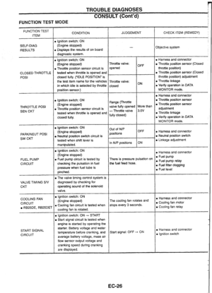 33
33 34
34 35
35 36
36 37
37 38
38 39
39 40
40 41
41 42
42 43
43 44
44 45
45 46
46 47
47 48
48 49
49 50
50 51
51 52
52 53
53 54
54 55
55 56
56 57
57 58
58 59
59 60
60 61
61 62
62 63
63 64
64 65
65 66
66 67
67 68
68 69
69 70
70 71
71 72
72 73
73 74
74 75
75 76
76 77
77 78
78 79
79 80
80 81
81 82
82 83
83 84
84 85
85 86
86 87
87 88
88 89
89 90
90 91
91 92
92 93
93 94
94 95
95 96
96 97
97 98
98 99
99 100
100 101
101 102
102 103
103 104
104 105
105 106
106 107
107 108
108 109
109 110
110 111
111 112
112 113
113 114
114 115
115 116
116 117
117 118
118 119
119 120
120 121
121 122
122 123
123 124
124 125
125 126
126 127
127 128
128 129
129 130
130 131
131 132
132 133
133 134
134 135
135 136
136 137
137 138
138 139
139 140
140 141
141 142
142 143
143 144
144 145
145 146
146 147
147 148
148 149
149 150
150 151
151 152
152 153
153 154
154 155
155 156
156 157
157 158
158 159
159 160
160 161
161 162
162 163
163 164
164 165
165 166
166 167
167 168
168 169
169 170
170 171
171 172
172 173
173 174
174 175
175 176
176 177
177 178
178 179
179 180
180 181
181 182
182 183
183 184
184 185
185 186
186 187
187 188
188 189
189 190
190 191
191 192
192 193
193 194
194 195
195 196
196 197
197 198
198 199
199 200
200 201
201 202
202 203
203 204
204 205
205 206
206 207
207 208
208 209
209 210
210 211
211 212
212 213
213 214
214 215
215 216
216 217
217 218
218 219
219 220
220 221
221 222
222 223
223 224
224 225
225 226
226 227
227 228
228 229
229![NISSAN GT-R 1998 Service Manual
TROUBLE DIAGNOSES
NISSAN
CONSULT
START
I 1
I SUB MODE BR455C
1 b SELECTeYSTEM
[ ENGINE
I
b SELECTDIAG MODE n]
WORK SUPPORT
SELF-DIAG
RESULTS
DATA MONITOR
ACTIVE TEST
FUNCTION TEST
,](/manual-img/5/57354/w960_57354-25.png "NISSAN GT-R 1998 Service Manual
TROUBLE DIAGNOSES
NISSAN
CONSULT
START
I 1
I SUB MODE BR455C
1 b SELECTeYSTEM
[ ENGINE
I
b SELECTDIAG MODE n]
WORK SUPPORT
SELF-DIAG
RESULTS
DATA MONITOR
ACTIVE TEST
FUNCTION TEST
,")