Page 33 of 230
 i
FUNCTION TEST MODE
CHECK ITEM (REMEDY)
FUNCTION
TEST
ITEM JUDGEMENT
CONDITION
lgnition switch: ON
(Engine stopped)
Displays the results of on b")
TROUBLE DIAGNOSES t i
CONSULT (Cont'd) i
FUNCTION TEST MODE
CHECK ITEM (REMEDY)
FUNCTION
TEST
ITEM JUDGEMENT
CONDITION
lgnition switch: ON
(Engine stopped)
Displays the results of on board
diagnostic system.
SELF-DIAG
RESULTS Objective
system
--
ignition switch: ON
(Engine stopped)
Throttle position sensor circuit is
tested when throttle is opened and
closed fully. ("IDLE POSITION" is
the test item name for the vehicles
in which idle is selected by throttle
position sensor.) Harness and connector
Throttle position sensor (Closed
throttle position)
Throttle position sensor (Closed
throttle position) adjustment
Throttle linkage
Venfy operation in DATA
MONITOR mode.
Throttle
valve:
opened OFF
ON
CLOSED THROTTLE
POSl Throttle valve:
closed
lgnition switch: ON
(Engine stopped)
Throttle position sensor circuit is
tested when throttle is opened and
closed fully.
Harness and connector
Throttle position sensor
Throttle position sensor
adjustment
Throttle linkage
Verify operation in DATA
MONITOR mode.
Range
(Throttle
valve fully opened
- Throttle valve
fully closed) More
than 3.0V THROTTLE POSl
SEN CKT
lgnition switch: ON
(Engine stopped)
Neutral position switch circuit is
tested when shift lever is
manipulated.
lgnition switch: ON
(Engine stopped)
Fuel pump circuit is tested by
checking the pulsation in fuel
pressure when fuel tube is
pinched. Out of
N/P
positions OFF
Harness
and connector
Neutral position switch
Linkage adjustment
PARWNEUT POSl SW CKT
In
N/P positions
Harness and connector
Fuel pump
Fuel pump relay
Fuel filter clogging
Fuel level
There
is pressure pulsation on
the fuel feed hose.
FUEL PUMP
CIRCUIT
--
The valve timing control system is
diagnosed by checking for
operating sound of the solenoid
valve.
lgnition switch: ON
(Engine stopped)
Cooling fan circuit is tested when
cooling fan is rotated.
VALVE
TIMING
SN
CKT
Harness and connector
Cooling fan motor
Cooling fan relay
COOLING
FAN
CIRCUIT RB25DE, RB25DET
The cooling fan rotates and
stops every
3 seconds.
lgnition switch: ON -+ START
Start signal circuit is tested when
engine is started by operating the
starter. Battery voltage and water
temperature before cranking, and
average battery voltage, mass air
flow sensor output voltage and
cranking speed during cranking
are displayed.
Harness and connector
lgnition switch
START
SIGNAL
CIRCUIT Start
signal: OFF 3 ON
Page 34 of 230
 --
CHECK ITEM (REMEDY)
FUNCTION TEST
ITEM CONDITION
JUDGEMENT
-
PWIST SIGNAL Locked position
Neutral position
Ignition
switch: ON
(Engine running)
P")
TROUBLE DIAGNOSES
CONSULT (Cont'd) --
CHECK ITEM (REMEDY)
FUNCTION TEST
ITEM CONDITION
JUDGEMENT
-
PWIST SIGNAL Locked position
Neutral position
Ignition
switch: ON
(Engine running)
Power steering oil pressure switch
circuit is tested when steering
wheel is rotated fully and then set
to a straight line running position. ON
OFF Harness and connector
Power steering oil pressure switch GO
CIRCUIT a Power steering oil pump
I VlAS SN CIRCUIT
0 RB20DE (UB),
RB25DE
The variable air intake system is
diagnosed by checking for opera-
tion of the actuator.
-
SWRL CONT SN
CIRCUIT
0 RB20DE (UB)
The air jet swirl control system is
diagnosed by checking for opera-
tion of the actuator.
-- -- -
a Vehicle speed sensor circuit is
tested when vehicle
is running at
a speed of 10 km/h (6 MPH) or
higher.
After warming up, idle the engine.
Ignition timing is checked by read-
ing ignition timing with a timing
light and checking whether it
agrees with specifications.
Harness and connector 877
Vehicle speed sensor
Vehicle
speed sensor input
signal is greater than 4 krnlh
(2 MPH).
VEHICLE SPEED
SEN CKT Speedometer
RS
Adjust ignition timing (by moving
camshaft position sensor or dis-
tributor)
HA
Camshaft position sensor drive
The
timing light indicates the
same value on the screen.
IGN
TIMING
ADJ
mechanism
la INJECTION SYS (Injector, fuel
pressure regulator, harness or
connector)
IGNITION SYS (Spark plug, igni-
tion coil, power transistor harness
or connector)
VACUUM SYS (Intake air leaks)
Oxygen sensor circuit
Oxygen sensor operation
Fuel pressure high or low
Mass air flow sensor
Air-fuel ratio feedback circuit
(injection system, ignition system,
vacuum system, etc.) is tested by
examining the oxygen sensor out-
put at 2,000
rpm under non-
loaded state. Oxygen sensor COUNT
More
than
5 times during 10 sec-
onds
MIXTURE
RATIO
TEST
- -- /
POWER BALANCE
Injector circuit (Injector, harness or
connector)
Ignition circuit (Spark plug, ignition
coil, power transistor harness or
connector)
Compression
Valve timing
After warming up, idle the engine.
Injector operation of each cylinder
is stopped one after another, and
resultant change in engine rotation
is examined to evaluate combus-
tion of each cylinder. (This is only
displayed for models where a
sequential
multipart fuel injection
system is used.)
D After warming up, idle the engine.
D IACV-AAC valve system is tested
by detecting change in engine
speed when IACV-AAC valve
opening is changed to
0%, 20%
and 80%. Difference
in engine speed is
greater than 25 rpm before
and after cutting off the injec-
tor of each cylinder.
Harness and connector
IACV-AAC valve
Air passage restriction between air
inlet and IACV-AAC valve
IAS (Idle adjusting screw) adjust-
ment
Difference
in engine speed is
greater than 150
rpm
between
when valve opening is at 80%
and at 20%.
IACV-AACN
SYSTEM
ECM PART NUMBER
Part number of the ECM equipped on the vehicle
can be read.
ECM: 2371 0-XXXXX
ECM-TCM: 23740-XXXXX
Page 35 of 230

TROUBLE DIAGNOSES
Symptom Matrix Chart
RELATION BETWEEN CONTROL ITEMS AND SENSORSfACTUATORS
@: High possibility to control damage 0: Low possibility to control damage
Sensors and actuators
1$1$1$ r I I
Crankshaft position sensor 1@1@1@
Ring gear crankshaft position sensor
[RB20DE (UB)] @
Mass air flow sensor
I Engine coolant temperature sensor I 0 I @ I 0 i I
Heated oxygen sensor 0
Knock sensor
Vehicle speed sensor
e? - 01 0
Throttle position sensor 000 C. $ Turbo pressure sensor (TIC) 0 0
Refrigerant pressure sensor
START
lgnition switch
@ 0
IGN 000
Air conditioner switch
Parklneutral position switch
Power steering oil pressure switch
Electrical load switch
Battery
voltage
0
injector @GO I
I power transistor I I I Ignition system I I I lgnition coil I I I I
AAC valve
Fuel DumD relav
. . I I I
2 o ECM & IGN coil relay I@l@l@ 1 I I % Auxiliary electric fan relay 3 - 2 Air conditioner relay
Canister purge control valve
0
Variable valve timing control solenoid valve
Variable air intake control solenoid valve
, (NA) Air jet swirl control solenoid valve
[RB20DE (UB)] 0
Turbo pressure control solenoid valve
(TW
FPCM (TIC)
%' Dropping resistor (TIC) 2. I I 5 Air regulator
Canister 0
Page 36 of 230
TROUBLE DIAGNOSES
Symptom Matrix Chart (Cont'd)
-RELATION BETWEEN TROUBLE SYMPTOMS AND SENSORS
-. - Sensors No I Hard
start start Rough
idle
Poor derivability Engine
stall
Symptom
@: High possibility 0: Low possibility
Crankshaft position
sensor (POS,
REF) Instantaneous
xeak
Ring gear crankshaft
position sensor
[RB20DE
(UB)]
s 1 Signal iigh output
,ow output
"
2 Power supply
Engine coolant tem-
perature sensor
iigh resistance
-ow resistance
- -- Heated oxygen sen-
sor
Knock sensor
iigh output
.ow output
Ipedshort
Vehicle s~eed sensor
Throttle position sen-
sor Jnstable output
'oar adjustment
Turbo pressure sen-
sor
(TIC)
Refrigerant pressure
sensor
Ignition switch (IGN)
k$n;pRnT)sw
i tch
Air conditioner switch
ParWneutral position
switch
Power steering oil
pressure switch
Electrical load switch
Multiplex communica-
tion line
Control unit power
supply
Sensor ground
Control unif and con-
nector
*: Fast idle
'oor contact
Vater intrusion
Page 37 of 230

Sensor-related problems I Symptom characteristics and ins~ection hints
Open Engine
will not start when either REF signal circuit or POS sign")
TROUBLE DIAGNOSES
Symptom Matrix Chart (Cont'd)
Sensor-related problems I Symptom characteristics and ins~ection hints
Open Engine
will not start when either REF signal circuit or POS signal circuit is open.
Neither fuel system nor ignition system outputs control signals.
Crankshaft position sensor
(POS, REF) Instanta-
neous break Symptoms
vary with the break time and the vehicle's driving conditions. Light
shock or surging will occur while the vehicle is being driven, and the engine will
stall at idle speed.
Ring gear crankshaft position
sensor
[RB20DE
(UB)]
Signal
Mass air flow sensor Open
Open
High output
Low output I Aidfuel
ratio becomes lean. Dirty hot wire or air entering the system could be the
cause. No
airfluel ratio compensation
is carried out during lean bum status. Drivability
may be affected.
Enters fail-safe mode. Driving under
2,400 rpm is allowed.
Airlfuel
ratio becomes rich. Black smoke may be noted. Poor contact at the
ground could be the cause.
Engine coolant temperature sen-
sor Open
Open
Opedshort
High resis-
tance
Low resis-
tance
Opedshort
Heated oxygen sensor
I
Airlfuel ratio becomes over-rich.
Same symptom as when signal wire is open.
Enters fail-safe mode. Malfunction indicator lamp comes ON. Ordinary driving is
allowed. Problems tend to occur when engine is cold or engine coolant tempera-
ture
is high.
Detects low engine coolant temperature. Problems tend to occur after engine
warm-up.
Detects high engine coolant temperature. Problems tend to occur when engine is
cold.
Base
aidfuel ratio is used.
lgnition timing is retarded within the knock control range. Lack of power may be
OpedShort
I noted.
Knock sensor lgnition
timing is retarded within the knock control range. Lack of power may be
High
Output
(noted.
Low output
1 lgnition timing may not be retarded when knock is detected.
Vehicle speed sensor
Throttle position sensor
Opedshort
Opedshort
Unstable out-
put
Poor adjust-
ment
Open
Turbo pressure sensor
(TE) Fuel
cut time becomes-shorter, or no fuel cut is observed.
Base idle speed is used. Fuel injection is not increased during acceleration.
AIT shift point changes for AfF vehicles.
Unnecessary cut-in fuel injection could be the cause. Poor contact at the ground
or control unit could be the cause.
ldle judgment is "OFF while idling. Condition returns
normal by turning the igni-
tion switch ON and OFF repeatedly.
Turbo pressure is judged zero. No remarkable malfunction will be detected.
Refrigerant pressure is judged high. ldle speed remains high while the air condi-
tioner is ON.
Refrigerant pressure sensor
Short Refrigerant pressure
is judged low. ldle speed remains low while the air condi-
tioner is ON.
lgnition switch (IGN)
lgnition switch (START)
Air conditioner switch Open
Engine
will not start because neither fuel system nor ignition system outputs con-
trol signals.
Engine starts in normal condition. Engine may not start when temperature is
extremefy
low.
Air conditioner will not operate. No other malfunction will be noted.
Park/neutral
position switch is judged "OFF. Target engine speed for cold engine
in
N or P position is reduced.
ParWneutral position switch is judged
"0N"I Fast Jdle is effective when the engine
is cold and the gear is in other than N and P posrtlons. Vehrcle excessrvely
creeps.
Open
Open
Parklneutral
position
switch
Short
Power steering oil pressure
switch Open
Engine may
stall when the steering wheel is turned while the vehicle is standstill
and the accelerator pedal is lightly pressed, or when the steering wheel is turned
Electrical load switch Short
Open
Open/short
Multiplex communication line
- -- during deceleration. '
Power steering switch is judged 'ON." Value will be compensated constantly.
Idle speed drops so that the engine can stall when electrical load is applied.
Torque reduction control is not performed. Therefore,
shift shock becomes
greater.
- -- -- -- -- Engine will not start because neither fuel system nor ignition system outputs con-
trol signals.
Open
Control unit power supply
- -- - - --- - - - - - O~edshort I Same symptoms as when sensor harness is open.
Sensor ground -- - Poor contact
Water intru-
sion - -- - - - - - -- -- In case of poor contact, the connector fitting may be loose. In case of water
intrusion, the engine stalls and become inoperative for a while. The engine may restart soon in some cases.
Control unit
and connector
Page 38 of 230
*va r TROUBLE DIAGNOSES
Symptom Matrix Chart (Cont'd)
"- RELATION BETWEEN TROUBLE SYMPTOMS AND ACTUATORS - Actuators No
Start Hard
start Rough
idle
Poor derivability Engine
stall
Symptom
. @: High possibility 0: Low possibility
Coil Open
Open
Open
Short
I Injection port Foreign
material
Ignition signal (Power
transistor drive signal)
Ignition primary signal
(Power transistor
ground)
Primary
si'de
.- c. - k Secondary side -
2 Power supply
Fuel pump relay
Auxiliary electric fan
relay
[RB25DE,
RB25DEfl
hen
Canister purge con-
trol valve
Variable valve timing
control solenoid valve
~
Variable air intake
control solenoid valve
Air jet swirl control
solenoid valve
Turbo pressure con-
trol solenoid valve
Injector ground (Total
ground) nstantaneous
reak
I ': Fast idle
Page 39 of 230

An open circuit causes no fuel injection to the corresponding cylinder, and the heated oxygen sensor output becomes lean. When the open circu")
TROUBLE DIAGNOSES
Symptom Matrix Chart (Cont'd)
An open circuit causes no fuel injection to the corresponding cylinder, and the heated oxygen sensor output becomes lean. When the open circuits are
observed at all cylinders, the engine will not start.
Actuator-related malfunction
Injector Symptom
characteristics and inspection hints
Drive
circuit
lgnition signal
(POW&
transistor
drive
siqnal)
(open
Injection Open
Short
Fuel pump relay
1 Open 1 Engine will not start. In case of instantaneous break, surging may occur.
A
short circuit causes continuous fuel injection to the corresponding cylinder, and
over-rich airlfuel ratio and misfire will be noted. When the short circuits are
observed at all cylinders, the engine will not start.
Foreign
material
Clogs
L
Foreign
material causes continuous fuel injection to the corresponding cylinder.
Symptoms vary with the condition how the injection port is clogged.
Aidfuel ratio
compensation factor becomes larger.
(1 10 to 125%)
Canister purge control valve Ignition primary
signal (Power
transistor ground)
Auxiliary electric fan relay
[RB25DE, RB25DETI
1 Short
Open
Open -
Open
Open
Leaks
Open
Open
lgnition coil
AAC valve
The valve purges constantly. In summertime, engine may stall at idle speed due
i to rich aidfuel ratio. In wintertime, various malfunctions may occur due to lean
airlfuel ratio.
An open circuit causes no fuel injection to the corresponding cylinder, and the '
heated oxygen sensor output becomes lean. When the open circuits are observed at all cylinders, the engine will not start. In case of instantaneous break, symptoms vary with the break time and the
vehicle's driving conditions. Light shock or surging will occur while the vehicle
is being driven.
The engine will stall when break time is long.
AAC valve is fully closed. Symptoms vary with the base engine speed. When it is
too low, engine may stall while the vehicle is decelerating or when the power
steering load or electrical load is applied.
Power
supply
s~de
primary
Second-
arY side
Power
supply
Drive
circuit
Open Open Auxiliary
electric fan will not operate even after warm-up is completed.
The valve
will not purge. Gasoline smell may be noted when the weather is hot.
Variable valve timing control
solenoid valve
Variable air intake control sole-
noid valve (NA)
Air jet swirl control solenoid
valve
[RB20DE
(UB)]
Injector ground (Total ground) lnstanta- Symptoms vary
with the break time and the vehicle's driving conditions. Surging neous break or engine stall may occur when the instantaneous break occurred during fuel
I I injection. I
Open
, Open
Short
Turbo pressure control solenoid
valve (TIC) Valve
timing not switched.
Variable air intake valve opens, and torque in low speed range is reduced.
Variable air intake valve closes, and torque in high speed range is reduced.
Open
Short Air jet
swirl control valve remains closed.
Air jet swirl control valve remains open.
Open
Open Swing valve opens earlier, and
maximum turbo pressure is reduced.
Engine will not start
because the injectors do not operate.
Page 40 of 230

RELATION BETWEEN TROUBLE SYMPTOMS AND ENGINE MECHANICAUACCESSORIES
Malfunction of the gasoline engine will not occur when the three elemen")
TROUBLE DIAGNOSES
Symptom Matrix Chart (Cont'd)
RELATION BETWEEN TROUBLE SYMPTOMS AND ENGINE MECHANICAUACCESSORIES
Malfunction of the gasoline engine will not occur when the three elements of combustion (compression
pressure, aidfuel mixture, and spark) are all normal. Though the
aidfuel mixture and the spark (ignition tim-
ing) are controlled by ECM
(.TCM) control unit, if the engine mechanical is malfunctioning,
a malfunction will
occur. (The table below shows universal cases. Some cases may not apply to the vehicle.)
Engine mechanical-related malfunction
0: High possibility 0: Medium possibility A: Low posstbility
I No I Hard
start start
I Air sucked in at oil level gauge
Air sucked in at oil filler cap
Loose air duct
(A-F/M downstream) 0 A
Misconnection of canister piping
0 A
Cracked intake manifold
0 A
Aidfuel
mix-
ture
PCV valve stuck open
Clogged fuel strainer
0 A
Clogged air cleaner element
Malfunctioning pressure regulator
A 0 0 0
Improper gasoline properties A000
EGR valve stuck open 0 0
Deposits on valve 0 0
Excessive canister purge volume
Misconnection of high-tension wire
Improperly adjusted ignition timing
Malfunctioning spark plug
High-tension wire leaks
A000
Spark Distributor cap leaks
A000
Compres-
Improper valve contact
sion pres-
. a080
sure Worn piston ring ~080
Others
Clogged catalytic converter or
exhaust system A00
Low base idle speed A
A
Foreign material (vinyl, etc.) in fuel 1 tank
Clogged radiator or capacitor
IIII
Rough idle I Poor drivability Engine stall
- - - - - - -- ': Fast
idle
Adding to the items listed above, check the following.
Wiring harness for tension Ground wires for loosenes nuids and oils for levels All connectors for connection Battery connections for loosenes and corrosion Drive belts for loosenes
 1
1 2
2 3
3 4
4 5
5 6
6 7
7 8
8 9
9 10
10 11
11 12
12 13
13 14
14 15
15 16
16 17
17 18
18 19
19 20
20 21
21 22
22 23
23 24
24 25
25 26
26 27
27 28
28 29
29 30
30 31
31 32
32 33
33 34
34 35
35 36
36 37
37 38
38 39
39 40
40 41
41 42
42 43
43 44
44 45
45 46
46 47
47 48
48 49
49 50
50 51
51 52
52 53
53 54
54 55
55 56
56 57
57 58
58 59
59 60
60 61
61 62
62 63
63 64
64 65
65 66
66 67
67 68
68 69
69 70
70 71
71 72
72 73
73 74
74 75
75 76
76 77
77 78
78 79
79 80
80 81
81 82
82 83
83 84
84 85
85 86
86 87
87 88
88 89
89 90
90 91
91 92
92 93
93 94
94 95
95 96
96 97
97 98
98 99
99 100
100 101
101 102
102 103
103 104
104 105
105 106
106 107
107 108
108 109
109 110
110 111
111 112
112 113
113 114
114 115
115 116
116 117
117 118
118 119
119 120
120 121
121 122
122 123
123 124
124 125
125 126
126 127
127 128
128 129
129 130
130 131
131 132
132 133
133 134
134 135
135 136
136 137
137 138
138 139
139 140
140 141
141 142
142 143
143 144
144 145
145 146
146 147
147 148
148 149
149 150
150 151
151 152
152 153
153 154
154 155
155 156
156 157
157 158
158 159
159 160
160 161
161 162
162 163
163 164
164 165
165 166
166 167
167 168
168 169
169 170
170 171
171 172
172 173
173 174
174 175
175 176
176 177
177 178
178 179
179 180
180 181
181 182
182 183
183 184
184 185
185 186
186 187
187 188
188 189
189 190
190 191
191 192
192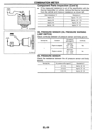 193
193 194
194 195
195 196
196 197
197 198
198 199
199 200
200 201
201 202
202 203
203 204
204 205
205 206
206 207
207 208
208 209
209 210
210 211
211 212
212 213
213 214
214 215
215 216
216 217
217 218
218 219
219 220
220 221
221 222
222 223
223 224
224 225
225 226
226 227
227 228
228 229
229
-RELATION BETWEEN TROUBLE SYMPTOMS AND SENSORS
-. - Sensors No I Hard
start start Rough
idle
Poor derivability Engine
stall
Symptom
@: H")

\"- RELATION BETWEEN TROUBLE SYMPTOMS AND ACTUATORS - Actuators No
Start Hard
start Rough
idle
Poor derivability Engine
stall
Symptom")