Page 161 of 230

FULLY AUTOMATIC AIR CONDITIONER
Magnet Clutch System Check
MAGNET CLUTCH
Disconnect the compressor connector. Apply approx. 12V to the compressor to check the magnet clutch
operation.
/;sn
AIR CONDITIONER RELAY QJg
Remove the air conditioner relay. Apply approx. 12V between the air conditioner relay terminals No. 1 and
2. Check the relay operation sound. Ec Check the continuity between terminals No. 3 and 5.
REFRIGERANT CHARGE AMOUNT AT
Connect the manifold gauge to the vehicle side service valve.
Check that the lower pressure side (gauge pressure) is more than approx. 0.1 8 MPa (1.8 kg/cm2.G). BR
ECM
Start the engine, and short-circuit the ECM terminal No. 14 to the ground. Check the magnet clutch operation.
INTAKE AIR TEMPERATURE SENSOR
Start the engine, and short-circuit the intake air temperature sensor terminal No. 1 to the ground. Check the Rs
maanet clutch o~eration.
Blower Fan Motor System Check
BLOWER FAN MOTOR
Disconnect the blower fan motor connector. Short-circuit the blower fan motor terminals No. 2 and 5 to El!, (
the ground. Apply approx. 12V to the terminal No. 6, and check the motor operation.
Connect the blower fan motor connector. Turn the ignition switch to the ON position, and change the fan sD
switch from 1st to 4th. Check the blower fan motor terminal No. 5 with an oscilloscope. When the termi-
nal No.
5 is normal according to the following table and the fan airflow does not change, this indicates a
faulty blower fan motor.
When the terminal No.
5 results differ from the following table and the fan airflow does not change, this
indicates either a faulty harness between the blower fan motor and automatic amplifier, or a faulty auto-
matic amplifier.
Page 162 of 230
FULLY AUTOMATIC AIR CONDITIONER
Blower Fan Motor System Check (Cont'd)
Terminal No. 5 (oscilloscope)
1 st speed
TI : Approx. 3.2 ms
Duty ratio: Approx. 20% 2nd
speed
3rd speed
T2: Approx. 2.2
ms
Duty ratio: Approx. 45%
T3: Approx. 1.44 ms
Duty ratio: bprox. 64%
4th speed
Duty ratio: Approx. 100%
Approx. 4 ms-Tx Duty ratio = Approx. 4 ms x 100%
BLOWER FAN RELAY
Remove the blower fan relay. Apply approx. 12V to the blower fan relay terminals No. 1 and 2. Check the
relay operation sound.
Check the continuity between terminals No.
3 and 5.
Actuator System Check
DOOR ACTUATOR MOTOR
Disconnect every door actuator connector. Check the continuity between each door actuator terminals No. 3
and 1, 3 and 2, 3 and 5, and 3 and 6.
DOOR ACTUATOR HARNESS
Check the continuity between the automatic amplifier and every actuator.
Check that there is no short-circuit between actuator driver signals. (If there is a short-circuit, the actua-
tors
will vibrate during operation.)
Page 163 of 230

FULLY AUTOMATIC AIR CONDITIONER
Symptom
Trouble Diagnosis for Each Symptom
No airflow
Airflow does not change. Operation check
Check blower fan motor operation. (Refer to "Blower Fan Motor Sys-
tem Check".)
The above is normal.
I Automatic amolifier 1 Faultv automatic amplifier
Faulty attachment of air mix door
rod, or air mix door lever
Faulty air mix door system
ElG
(damage, lock, etc.)
Malfunctioning unit
Blower fan motor Probable cause
Faulty blower fan motor
Check attachment status of the air
mix door actuator.
Common item (Check and confirm this
item along with the fol-
lowing three items.)
Air mix door
Abnormal display in self-diagnosis
step
3
Check that the air mix door oper-
ates when the temperature
adjust-
ment dial is set to
18OC or 32°C.
Faulty sensor (Refer to 'Component a
Parts Inspection".)
Faulty sensor harness
Air
mix door actuator
Air mix door actuator
Abnormal display in self-diagnosis
step 2
Magnet clutch does not operate
Magnet clutch Refer
to 'Magnet Clutch System R8
with AUTO switch, or A/C switch. Check".
I Faulty
air mix door actuator
Faulty air mix door actuator system AT
hamess
(Refer to "Actuator System Check".)
BW
Refer to "Actuator System Check".
@'i?
Sensor
Tem- perature
control mal-
function No
cool airflow
(Flow amount is normal.)
ngeranr
cnarge
amounr.
( Cooler cycle 2 ~erformance. I Refer to 'Performance Test". I
The above is normal. I Automatic amolifier 1 Faulty automatic amplifier I
After warming up, the heater core
inlet and outlet hoses are not warm. 1 Coolant I
Engine coolant failure
Clogged heater hose or heater core
No warm airflow
(Flow
amount is normal.)
The above is normal. Automatic amplifier
1 Faulty automatic amplifier
Blower fan motor speed does not
change even when the fan switch is Blower fan motor
changed. Refer
to "Blower Fan Motor System
Check".
I
When the fan switch is in 4th, Faulty aspirator
smoke is not drawn in from the
in-
Aspirator Clogged
or disconnected aspirator
vehicle sensor inlet. duct
Large
in-vehicle tem-
perature difference in
relation to temperature
setting Check the setting difference
between the set temperature and
control temperature. Error
in temperature difference set-
ting
- The above isnormal.- Automatic amplifier Faulty automatic amplifier
Faulty attachment of mode door
lock, mode door link, or mode door
Check mode door operation. Mode door lever
Faulty mode door system (damage,
lock, etc.)
Faulty mode door actuator
Abnormal display in self-diagnosis Faulty mode door actuator system
step
3 Mode door actuator
harness (Refer to "Actuator System
Check".)
Air
outlet does not switch.
Normal display in self-diagnosis
Mode door actuator
step
3
Refer to "DOOR ACTUATOR
HARNESS", "Actuator System
Check".
The above is normal.
I Automatic amplifier I Faulty automatic amplifier - - I I Faulty attachment of intake door
Check intake door operation. lntake
door lever
Faulty intake door system (damage,
lock, etc.)
~aulG intake door actuator
Faulty intake door actuator system
hamess (Refer to "Actuator System
Check".)
Abnormal
display in self-diagnosis
door step 3 Air inlet does fiot switch.
Normal display in self-diagnosis
lntake door actuator
step
3
Refer to "DOOR ACTUATOR
HARNESS", "Actuator System
Check".
I I The above is normal. I Automatic amplifier I Faulty automatic amplifier
Page 164 of 230

FULLY AUTOMATIC AIR CONDITIONER
ln-vehcle sensor characterlstlc and connector I
Temperature "C HAK0669D
Ambient sensor characteristic and connector
Temperature
"C ELZ0174C
I Sunload sensor characteristic and connector
I Sunload kW/m2 (kcaVm2 h) HAK0666C
cake alr temperature sensor characlerlstrc and connector
Temperature
'C ~~~0667~1
Component Parts Inspection
IN-VEHICLE SENSOR
Disconnect the in-vehicle sensor connector. Check the resistance
between the sensor connector terminals No.
1 and 2.
AMBIENT SENSOR
Disconnect ambient sensor connector. Check the resistance
between the sensor connector terminals No.
1 and 2.
SUNLOAD SENSOR
Disconnect the sunload sensor connector.
Turn the ignition switch
ON.
Check that the voltage between the automatic amplifier con-
nector (vehicle side) terminal No.
34 and body ground, is
approx.
4.6V.
When normal, proceed to step
5.
When abnormal, the automatic amplifier is faulty. Or, the har-
ness between the automatic amplifier and
sunload sensor is
faulty. Turn the ignition switch
OFF.
Connect the sunload sensor connector.
Turn the ignition switch
ON.
Check the voltage between the automatic amplifier connector
(vehicle side) terminal
No. 34 and body ground.
When indoors, check the voltage by applying a light of approx.
60W. (Check the voltage with the light placed close to and
away from the sensor.)
The
sunload during a sunny day is equivalent to approx.
767
W/m2 (660 kcal/m2- h).
INTAKE AIR TEMPERATURE SENSOR
Disconnect the intake air temperature sensor connector. Check the
resistance between the sensor connector terminals No.
1 and 2.
THERMAL TRANSMITER
Refer to EL section ("Component Parts Inspection", "COMBINA-
TION
METER").
HA-I 8
Page 165 of 230

ELECTRICAL SYSTEM
SECTION EL
CONTENTS
CENTRAL DOOR LOCK SYSTEM ................................. 2
Component Parts Location .......................................... 2
Circuit Diagram ............................................................ 2
Combination Meter (meter control unit) Input/
Output Signal Specifications
........................................ 2
Inspection before Trouble Diagnoses ......................... -3
Trouble Diagnoses ....................................................... 3
REMOTE CONTROL ENTRY SYSTEM .......................... 4
Component Parts Location .......................................... 4
Circuit Diagram ............................................................ 4
Remote Control Entry Control Unit Input/Output
Signal Specifications
.................................................... 5
System Check ............................................................. -5
Inspection before Trouble Diagnoses .......................... 6
Trouble Diagnoses ....................................................... 6
Component Parts inspection ....................................... 6
ID Code Entry Procedure ............................................ 7
POWER WINDOW SYSTEM ........................................... 8
System Description ..................................................... -8
Precautions ................................................................. -8
Component Parts Location .......................................... 8
Circuit Diagram ............................................................ 9
Power Window Main Switch Input/Output Signal
Specifications
............................................................... 9
Inspection before Trouble Diagnoses ........................ 11
Trouble Diagnoses .................................................... 11
SUNROOF SYSTEM ...................................................... 12
Component Parts Location ........................................ 12
Circuit Diagram .......................................................... 12
Sunroof Switch and Sunroof Motor Assembly
lnputiOutput Signal Specifications
............................. 12
AUTO LIGHT SYSTEM ................................................. 1 3
Component Parts Location ........................................ 13
Auto Light Control Unit Input/Output Signal
Specifications
............................................................. 13
Circuit Diagram ........................................................ 14
Trouble Diagnoses .................................................. I 4
..................................... XENON HEADLAMP SYSTEM 15
Trouble Diagnoses ..................................................... 15
IGNITION KEY-OPERATED ILLUMINATION
SYSTEM
................................................................... 7
Component Parts Location ........................................ 17
.......................................................... Circuit Diagram 17
Meter Control Unit InputlOutput Signal
....................................................... Specifications 1 7
METER ........................................................................\
18
Corn bination Meter .................................................... 18
Triple Meter ................................................................ 20
................................................ COMBINATION METER 21
.................................................... System Description 21
........................................ Component Parts Location 21
Diagnosis Function .................................................... 21
................................... Meter-related Circuit Diagram 22
..................................................... Trouble Diagnoses 23
Combination Meter InpuVOutput Signal
Specifications
............................................................ -25
..................................... Component Parts Inspection 26
TRIPLE METER ............................................................. 29
Special Service Tool ................................................... 29
........................................ Component Parts Location 29
Circuit Diagram .......................................................... 29
Triple Meter InputfOutput Signal Specifications ........ 30
Component Parts Inspection ..................................... 30
IGNITION KEY WARNING BUZZER AND LIGHT
WARNING BUZZER
...................................................... 31
Component Parts Location ........................................ 31
Circuit Diagram .......................................................... 31
Meter Control Unit InpuVOutput Signal
Specifications
............................................................. 31
FRONT WIPER .............................................................. 32
Component Parts Location ........................................ 32
Circuit Diagram .......................................................... 32
Front Wiper Input/Output Signal Specifications ........ 32
Page 166 of 230

REAR WIPER ................................................................ 33 Meter Control Unit InpuVOutput Signal
Component
Parts Location ....................................")
CONTENTS (cm9d)
REAR WIPER ................................................................ 33 Meter Control Unit InpuVOutput Signal
Component
Parts Location ....................................... .33 Specifications -34 ............................................................
Circuit Diagram .......................................................... 33 WIPER DEICER ............................................................. 35
Rear Wiper Amplifier
Input/Output
Signal Component Parts Location
.35 @I .......................................
Specifications ............................................................ .33 Circuit Diagram 35 ..........................................................
REAR DEFOGGER AND HEATER MIRROR ............... 34 Wiper Deicer Switch InpuVOutput Signal
Component Parts Location ..34 Specifications.. 35 EG ...................................... ........................................................... .......................................................... Circuit Diagram 34
Page 167 of 230
 1 11el j I 1
Combination meter
(Meter C/U) connector")
CENTRAL DOOR LOCK SYSTEM
Component
Parts Location
Door lock relay
LOCK -
Door lock relay
connector
1 LOCK 1
TK20 I I 5\41 1 (Brown) 1 11el j I 1
Combination meter
(Meter C/U) connector
I
Circuit Diagram
Driver door lock
Remote control entry
SW signal C/U connector
Lock signal
18. Unlock sign311 5 T 1
PMI main SW
(Central door lock SW)
----- I . RH door1
actuator 1 I I I Rear LH door I lock actuator I I I,,,,,,,------J
Driver door lock
actuator SW
P/'W main SW connector PNV main SW connector
(2-door Coupe) 1 (4-door Sedan) OCC3324 C
Combination Meter (meter control unit) Input/
Output Signal Specifications
-
I
. . 4 1 Driver door lock switch signal I
Specification
Approx. OV
Locked (OFF)
5
18
55
56
60
Operation or condition
Unlocked (ON1
Terminal No.
Approx.
5V
Signal name
Central door lock switch unlock signal
Central door lock switch lock signal
Ground Passenger and rear
RH 8 LH door lock
actuator lock signal
Passenger and rear RH & LH door lock actuator unlock siqnal Unlocked
(ON)
Operation other than above (OFF)
Locked (ON)
Operation other than above (OFF)
-
Central door lock switch is locked.
Central door lock switch is unlocked. Approx.
OV
Approx. 5V
Approx.
OV
Approx. 5V
Approx.
OV
Changes from approx. 12 to OV and back
to approx. 12V.
Changes from approx.
12 to OV and back
to approx. 12V.
Page 168 of 230

CENTRAL DOOR LOCK SYSTEM
Symptom
Passenger door lock and rear
RH & LH door locks do not lock or unlock with the
central door lock switch.
Passenger door lock, rear
RH door lock,
or rear LH dooc lock do not lock or unlock
with the central door lock switch.
Passenger door lock and rear
RH & LH door locks do not lock or unlock with the
driver door lock knob. (They operate
properly with the central door lock switch.)
Inspection before Trouble Diagnoses
Check that components connectors are properly connected.
Trouble Diagnoses
SYMPTOM CHART
Malfunctioning item
Door lock relay circuit Possible
cause E8G Faulty power window main switch (central door lock switch)
Power window main switch circuit
Faulty door lock relay
Faulty door lock relay to combination meter (meter control unit)
BR harness
0 Faulty power window main switch (central door lock switch) to
combination meter (meter control unit) harness
Faulty power window main switch (central door lock switch) ground
circuit
I Faulty door lock relay to door lock actuator harness
Door lock actuator circuit
Combination meter
(meter control unit)
0 Faulty door lock actuator Faulty door lock actuator to door lock relay harness
0 Faulty combination meter (meter control unit) ST
Driver door lock switch circuit
0 Faulty driver door lock switch . Faulty driver door lock switch to combination meter (meter control
unit) harness
Combination meter (meter control unit)
Faulty driver door lock switch ground circuit
Faulty combination meter (meter control unit) m
 1
1 2
2 3
3 4
4 5
5 6
6 7
7 8
8 9
9 10
10 11
11 12
12 13
13 14
14 15
15 16
16 17
17 18
18 19
19 20
20 21
21 22
22 23
23 24
24 25
25 26
26 27
27 28
28 29
29 30
30 31
31 32
32 33
33 34
34 35
35 36
36 37
37 38
38 39
39 40
40 41
41 42
42 43
43 44
44 45
45 46
46 47
47 48
48 49
49 50
50 51
51 52
52 53
53 54
54 55
55 56
56 57
57 58
58 59
59 60
60 61
61 62
62 63
63 64
64 65
65 66
66 67
67 68
68 69
69 70
70 71
71 72
72 73
73 74
74 75
75 76
76 77
77 78
78 79
79 80
80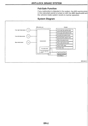 81
81 82
82 83
83 84
84 85
85 86
86 87
87 88
88 89
89 90
90 91
91 92
92 93
93 94
94 95
95 96
96 97
97 98
98 99
99 100
100 101
101 102
102 103
103 104
104 105
105 106
106 107
107 108
108 109
109 110
110 111
111 112
112 113
113 114
114 115
115 116
116 117
117 118
118 119
119 120
120 121
121 122
122 123
123 124
124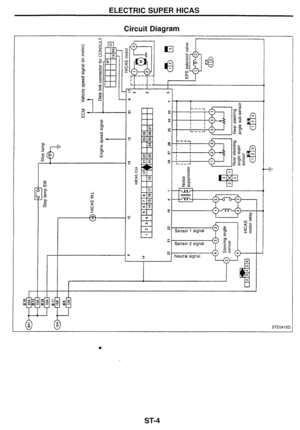 125
125 126
126 127
127 128
128 129
129 130
130 131
131 132
132 133
133 134
134 135
135 136
136 137
137 138
138 139
139 140
140 141
141 142
142 143
143 144
144 145
145 146
146 147
147 148
148 149
149 150
150 151
151 152
152 153
153 154
154 155
155 156
156 157
157 158
158 159
159 160
160 161
161 162
162 163
163 164
164 165
165 166
166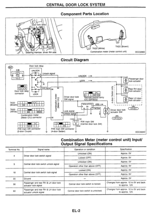 167
167 168
168 169
169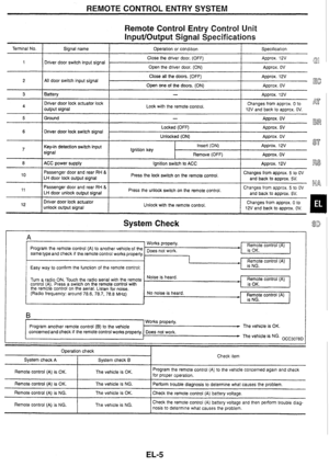 170
170 171
171 172
172 173
173 174
174 175
175 176
176 177
177 178
178 179
179 180
180 181
181 182
182 183
183 184
184 185
185 186
186 187
187 188
188 189
189 190
190 191
191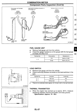 192
192 193
193 194
194 195
195 196
196 197
197 198
198 199
199 200
200 201
201 202
202 203
203 204
204 205
205 206
206 207
207 208
208 209
209 210
210 211
211 212
212 213
213 214
214 215
215 216
216 217
217 218
218 219
219 220
220 221
221 222
222 223
223 224
224 225
225 226
226 227
227 228
228 229
229
Terminal No. 5 (oscilloscope)
1 st speed
TI : Approx. 3.2 ms
Duty ratio: Approx. 20% 2nd
speed
3rd speed
T2: Appr")