Page 105 of 230

TCSlABS SYSTEM
Precautions for Trouble
Diagnosis
After performing trouble diagnosis, be sure to erase trouble stored in memory.
Refer to "CONSULT for
TCS/ABS Control Unit Control System"
(BR-27), "Self-diagnosis for TCSIABS
Control Unit Control System"
(BR-34), "CONSULT for Throttle Control Unit Control System" (BR-37) or
"Self-diagnosis for Throttle Control Unit Control System"
(BR-41).
The concerns that are difficult to duplicate may be caused by faulty electrical connections. Move harnesses
or harness connectors by hand to check if there is any poor mating of connector halves or faulty connec-
tion. Do not force to open a connector terminal when using a circuit tester for inspection.
Read GI section thoroughly in advance and make sure of all the general precautions.
Basic Inspection
BASIC INSPECTION 1 - Brake fluid level and leakage
1. Check brake fluid level in reservoir tank. Replenish brake fluid if necessary.
2. Check for leakage at or around brake piping and ABS actuator. If leakage or seepage is noted, proceed
as follows:
If ABS actuator connectors are loose, tighten to specified torque. Recheck to ensure that leakage is no
longer present.
If flare nut threads at piping connectors or actuator threads are damaged, replace faulty parts with new
ones. Recheck to ensure that leakage is no longer present.
If brake fluid leaks through areas other than actuator connectors, wipe off using a clean cloth. Recheck
for leakage or seepage. If necessary, replace faulty parts with new ones.
If brake fluid leaks at or seeps through ABS actuator, wipe off using a clean cloth.
Recheck for leakage or seepage. If necessary, replace ABS actuator with new one.
CAUTION:
ABS actuator cannot be disassembled. Do not attempt to disassemble it.
3. Check brake disc rotors and pads for proper operation.
BASIC INSPECTION 2 - Loose power line terminal
Check battery terminals (positive and negative) and battery mounting (ground) for looseness. If necessary,
tighten to specified torque. Check the battery for lower voltage.
BASIC INSPECTION 3 - SLlP indicator lamp, TCS OFF indicator lamp and ABS warning
lamp
Turn ignition switch "ON" to ensure that TCS OFF indicator lamp lights up. If TCS OFF indicator lamp does
not light, check TCS OFF indicator lamp circuit.
Turn ignition switch
"ON" to ensure that SLlP indicator lamp lights
up. If SLlP indicator lamp does not light,
check SLlP indicator lamp circuit.
Turn ignition switch "ON" to ensure that ABS warning lamp lights up. If ABS warning lamp does not light,
check ABS warning lamp circuit.
Check that the SLlP indicator lamp and the ABS warning lamp go off approx.
1 second after the engine
has started. If either of the lamps still remains on, perform the self-diagnosis for TCSIABS control unit
control system and the self-diagnosis for throttle control unit control system.
After driving vehicle at approx. 30
km/h
for approx.
1 minute, check to ensure that the SLlP indicator lamp
and the ABS warning lamp are off. If either of the lamps still remains on, perform the self-diagnosis for
TCS/ABS
control unit control system and the self-diagnosis for throttle control unit control system.
Check that the TCS OFF indicator lamp turns ON and OFF when the TCS OFF switch is turned to
ON
and OFF respectively, with the engine running. If the lamp status does not correspond to the switch
position, check the TCS OFF switch circuit.
Check that the TCS OFF indicator lamp goes off when the engine has started with the TCS OFF switch
OFF. If the TCS
OFF indicator lamp does not go off even 10 seconds after the engine has started, per-
form the self-diagnosis for TCSIABS control unit control system and the self-diagnosis for throttle control
unit control system.
After driving vehicle at approx.
30 kmlh for approx. 1 minute with the TCS OFF switch OFF, check to ensure
that the TCS OFF indicator lamp is off. If the TCS OFF indicator lamp lights up, perform the
self-diagno-
sis for
TCS/ABS
control unit control system and the self-diagnosis for throttle control unit control system.
After performing self-diagnosis procedures, be sure to erase trouble stored in memory.
Page 106 of 230

TCS/ABS SYSTEM
CONSULT for TCS/ABS Control Unit Control
System
CONTROL UNIT PART NUMBER
The part number that is shown on the control unit label and CON-
SULT
A/T model: 47850 AA310
M/T model: 47850 AA110
SELF-DIAGNOSIS PROCEDURE rn
Collect information on the concern from the customer, and then
perform basic inspections.
Turn ignition switch OFF and connect CONSULT connector to
data link connector for CONSULT on the vehicle.
ST
Start engine and drive vehicle at approx. 30 km/h for approx.
1 minute.
Stop vehicle with engine running and touch "START", "ABS"
38
and "SELF-DIAG RESULTS" sequentially on the CONSULT
screen.
If "START" is touched immediately after engine is started y;rjn
or ignition switch is turned on, "ABS" may not be dis-
played on "SELECT SYSTEM" screen. To display "ABS", E~
repeat the self-diagnosis procedure from the beginning.
Self-diagnosis results are displayed on the screen. (Touch
"PRINT' to print out the self-diagnosis results,
if necessary.) 8~ If "NO FAIL" is displayed, inspect the SLlP indicator lamp, the
TCS OFF indicator lamp and the ABS warning lamp. Refer to
the previous page.
Perform appropriate inspection from the self-diagnostic results
mode and repair or replace faulty parts.
Start engine and drive vehicle at approx.
30 km/h for approx.
1 minute.
Recheck to ensure that there is no other malfunction.
Turn ignition switch OFF to prepare for erasing the trouble
stored in memory.
Start engine and touch "START",
"ABS", "SELF-DIAG
RESULTS" and "ERASE" sequentially on the CONSULT
screen to erase the trouble stored in memory.
If the trouble stored in memory is not erased, repeat step
6.
Drive vehicle at approx. 30 krn/h for approx. 1 minute and then
confirm that the TCS OFF indicator lamp, the
SLlP indicator
lamp, and the ABS warning lamp are OFF.
TCS OFF switch is not in cancel condition.
Page 107 of 230

SELF-DIAGNOSTIC RESULTS MODE
Diagnostic item Diagnostic item is detected when ...
Circuit for front right wheel sensor")
TCS/ABS SYSTEM
CONSULT for TCS/ABS Control Unit Control
System (Cont'd)
SELF-DIAGNOSTIC RESULTS MODE
Diagnostic item Diagnostic item is detected when ...
Circuit for front right wheel sensor is open. Or an abnormally high input voltage is
entered due to short to battery.
Circuit for front left wheel sensor is open. Or an abnormally high input voltage is entered
due to short to battery.
Circuit for rear right wheel sensor is open. Or an abnormally high input voltage is enterec
due to short to battery. Check
item
FR RH SENSOR
[OPEN]
FR LH SENSOR
[OPEN]
REAR SENSOR
[OPEN]
RR LH SENSOR
[OPEN] Circuit for rear left
wheel sensor is open. Or an abnormally high input voltage is entered
due to short to battery.
Front right wheel sensor is short-circuited or shorted to ground, or gap between the
wheel sensor and the sensor rotor is large. An abnormally low input voltage is entered
and input signal is abnormal.
FR
RH SENSOR
[SHORT) Wheel
sen-
sor circuit
FR LH SENSOR
[SHORTJ Front
left wheel sensor is short-circuited or shorted to ground, or gap between the wheel
sensor and the sensor rotor is large. An abnormally low input voltage is entered and
input signal is abnormal.
Rear right wheel sensor is short-circuited or shorted to ground, or gap between the
wheel sensor and the sensor rotor is large. An abnormally low input
vottage is entered
and input signal is abnormal.
Rear left wheel sensor is short-circuited or shorted to ground, or gap between the wheel
sensor and the sensor rotor is large. An abnormally low input voltage is entered and
input signal is abnormal.
Circuit for front right inlet ABS solenoid valve is open, or an output voltage is much lower
than the specified value due to short to ground.
Circuit for front
left inlet ABS solenoid valve is open, or an output voltage is much lower
than the specified value due to short to ground.
RR
RH SENSOR
[SHORTJ
RR LH SENSOR
[SHORV
FR RH IN ABS SOL
[OPEN]
FR LH
IN ABS SOL
[OPEN]
REAR IN ABS SOL
[OPEN] Circuit
for rear inlet ABS solenoid valve is
open, or an output voltage is much lower than
the specified value due to short to ground.
-
FR RH IN ABS SOL
[SHORT]
- - - -- - - - -
Circuit for front right inlet ABS solenoid valve is shorted, or an output voltage is much
higher than the specified value due to short to battery.
Circuit for front left inlet ABS solenoid valve is shorted, or an output voltage is much
higher than the specified value due to short to battery.
Circuit for rear inlet ABS solenoid valve is shorted, or an output voltage is much higher
than the specified value due to short to battery.
Circuit for front right outlet ABS solenoid valve is open, or an output voltage is much
lower than the specified value due to short to ground.
Circuit for front left outlet
ABS solenoid valve is open, or an output voltage is much lower
than the specified value due to short to ground.
FR
LH IN
ABS SOL
[SHORTJ
REAR IN ABS SOL
[SHORT] Solenoid and
circuit
FR RH OUT ABS SOL
[OPEN]
FR LH OUT ABS SOL
[OPEN]
REAR
OUT ABS SOL
[OPEN]
- --
Circuit for rear outlet ABS solenoid valve is open, or an output voltage is much lower
than the specified value due to short to ground.
Circuit for front right outlet ABS solenoid valve is shorted, or an output voltage is much
higher than the specified value due to short to battery.
Circuit for front left outlet
ABS solenoid valve is shorted, or an output voltage is much
higher than the specified value due to short to battery.
Circuit for rear outlet
ABS solenoid valve is shorted, or an output voltage is much higher
than the specified value due to short to battery.
ABS motor turns ON when control unit sends OFF signal. ABS motor circuit is open or
shorted to ground.
ABS motor turns OFF when control unit sends ON
signzl. Relay control wire is broken.
FR RH OUT ABS SOL
[SHORT]
FR LH OUT ABS SOL
[SHORT]
REAR
OUT ABS SOL
[SHORT]
ABS MOTOR
[ON FAILURE]
ABS motor,
motor relay
and circuit
ABS
MOTOR
[OFF FAILURE]
Page 108 of 230
![NISSAN GT-R 1998 Service Manual
TCS/ABS SYSTEM
CONSULT
for TCSlABS Control Unit Control
System
(Contd)
Diagnostic item Check item
Diagnostic
item is detected when ...
ABS ACTUATOR RELAY
b~ FAILURE] ABS
actuator rel](/manual-img/5/57354/w960_57354-107.png "NISSAN GT-R 1998 Service Manual
TCS/ABS SYSTEM
CONSULT
for TCSlABS Control Unit Control
System
(Contd)
Diagnostic item Check item
Diagnostic
item is detected when ...
ABS ACTUATOR RELAY
b~ FAILURE] ABS
actuator rel")
TCS/ABS SYSTEM
CONSULT
for TCSlABS Control Unit Control
System
(Cont'd)
Diagnostic item Check item
Diagnostic
item is detected when ...
ABS ACTUATOR RELAY
b~ FAILURE] ABS
actuator relay turns ON when control unit sends OFF signal. Actuator relay is short-
circuited to ground. ABS
actuator
relay and
circuit
ABS
ACTUATOR RELAY
[OFF FAILURE] ABS
actuator relay turns OFF when control unit sends ON signal. Relay control wire is
broken.
BAlTERY VOLTAGE
[VB-IiIGH] TCSIABS
control unit
power supply
and ground
circuit
TCSIABS
control unit battery voltage is abnormally high.
BAlTERY VOLTAGE
[VB-LOW TCSIABS control unit battery voltage is abnormally low.
- -
Function of calculation in TCS/ABS control unit has failed. TCSIABS
control unit
CONTROL
UNIT
ABS motor,
motor relay and circuit
ABS
MOTOR
[LOCK FAILURE] ABS
motor speed is abnormally low.
Engine speed signal is interrupted or signal wire is suspected to be broken.
TCSIABS control unit connector or ECM-TCM or ECM connector is poorly connected. Engine
speed signal circuit
ENGINE
SPEED SIG
Circuit for
the commu-
nication line
between
TCSIABS
control unit
and throttle control unit
The communication line between TCSIABS control unit and throttle control unit is open
or shorted.
Throttle control system (throttle control unit, peripheral harness, and throttle actuator)
is abnormal.
TCSIABS control unit or throttle control unit battery voltage is low.
THROTLE
POSl
SIG
Engine main components (crankshaft position sensor, mass air flow sensor, engine cool-
ant temperature sensor, ignition primary signal, throttle position sensor, and motor throttle
position sensor) are abnormal. Engine sys-
tem
ENGINE SYSTEM
Total control
signal
1
(multiple sig- nal) for
engine,
A/l
and TCSI
ABS
Total control signal (multiple signal) for engine, AIT and TCS/ABS is abnormal (open or
shorted communication harness, faulty connections, abnormal
TCS/ABS control unit or
ECM-TCM or ECM).
TCSIABS control unit power is momentarily cut off or decreased.
LAN
SIGNAL
1
Total control signal (multiple signal) for engine,
and TCS/ABS is abnormal (open or
shorted communication harness, faulty connections, abnormal
TCS/ABS control unit or
ECM.TCM or ECM).
ECM.TCM or ECM starter switch is stuck to ON.
The starter switch is ON for 10 seconds or longer even after the engine has started.
(This is not
a malfunction.)
ECM-TCM or ECM is abnormal. (Total control signal (multiple signal) for engine,
A/T
and TCSIABS is malfunctioning. Or the system is in the process of CPU back up.)
TCSIABS is abnormal. Total
control
signal
2
(multiple sig-
nal) for
engine,
PA
and TCSI
ABS
LAN
SIGNAL
2
LAN SIGNAL 3
Page 109 of 230

Diagnostic item
LAN CIRCUIT
1
LAN CIRCUIT 2
Diagnostic item is detected when ... I Check item
NOTE:
If \"NO FAIL")
TCSfABS SYSTEM
CONSULT for
TCSfABS Control
Unit Control
System (Cont'd)
Diagnostic item
LAN CIRCUIT
1
LAN CIRCUIT 2
Diagnostic item is detected when ... I Check item
NOTE:
If "NO FAILn is displayed as a result of the CONSULT self-diagnosis when the ABS warning lamp is lit, inspect the engine speed
signal circuit.
If "ABSn is not displayed on "SELECT SYSTEM" screen, check ABS control unit and data link connector circuit, and make sure of the CONSULT card number. If "ENGINE SYSTEM", "LAN SIGNAL 1". "LAN SIGNAL 2", "LAN SIGNAL 3, "LAN CIRCUIT 1" or "LAN CIRCUIT 2" is displayed
on the screen, perform the self-diagnosis for the
ECM.TCM
or ECM.
If "THROlTLE CONTROLLER COMMUNICATIONn is displayed on the screen, perform the self-diagnosis for throttle control unit.
Total control signal (multiple signal) for engine, All and TCSIABS is abnormal (open or
shorted communication harness,-faulty connections, abnormal TCSIABS control unit or
ECM.TCM
or ECM).
ECM.TCM
or ECM power is cut
off or decreased for 2 seconds or longer.
Total control signal (multiple signal) for engine,
ArT and TCSIABS is suspected to be
interrupted (open or shorted communication harness, faulty connections, abnormal
TCS/ABS
control unit or ECM TCM or ECM).
ECM.TCM or ECM power is cut off or decreased for 2 seconds or longer.
DATA
a
1.
2.
3.
4.
5.
a
signal 1, 2
(multiple sig-
nal) for
and
TCSI
ABS
MONITOR PROCEDURE
Refer to CONSULT Instruction Manual for details on data
monitor function.
Turn ignition switch OFF.
Connect CONSULT connector to data link connector for
CON-
SU LT.
Turn ignition switch
ON.
Touch "START" on CONSULT screen.
Touch "ABS" on CONSULT screen.
If "START" is touched immediately after engine is started
or ignition switch is turned ON, "ABS" may not be dis-
played on "SELECT SYSTEM" screen. To display "ABS",
repeat the data monitor procedure from the beginning.
Touch "DATA MONITOR".
Touch "SETTING" to set recording condition.
Touch "AUTO TRIG", "LONG TIME" and then
"ENTER".
Return to "SELECT MONITOR ITEM" screen and touch "C/U
INPUT ITEM",
"ALL SIGNALS" or "SELECTION FROM
MENU". Refer to "DATA MONITOR MODE" on the next page.
10. Touch "START".
11. Display data monitor.
12. If necessary, sequentially touch "REC START, "REC STOP",
"DATA DISPLAY", "NUMBER PRINT" and "PRINT" to print out
the data.
Page 110 of 230
![NISSAN GT-R 1998 Service Manual
TCS/ABS SYSTEM
CONSULT
for TCSfABS Control Unit Control
System (Contd)
DATA MONITOR MODE --
I ~elect-monitor item I
Display
signals Selection from
Remarks
menu
FR RH SEN
[kmlh] Disp](/manual-img/5/57354/w960_57354-109.png "NISSAN GT-R 1998 Service Manual
TCS/ABS SYSTEM
CONSULT
for TCSfABS Control Unit Control
System (Contd)
DATA MONITOR MODE --
I ~elect-monitor item I
Display
signals Selection from
Remarks
menu
FR RH SEN
[kmlh] Disp")
TCS/ABS SYSTEM
CONSULT
for TCSfABS Control Unit Control
System (Cont'd)
DATA MONITOR MODE --
I ~elect-monitor item I
Display
signals Selection from
Remarks
menu
FR RH SEN
[kmlh] Displays vehicle speed computed based on
front right wheel sensor signal.
zc
FR LH SEN [kmlh] Displays
vehicle speed computed based on
front left wheel sensor signal.
AT
Displays vehicle speed computed based on
rear right wheel sensor signal.
Displays vehicle speed computed based on
rear left wheel sensor signal.
REAR
SEN
[kmlhll
RR LH SEN
lkmlhll
FIR IN SOL [ON-OFF]
I O
FIR OUT SOL [ON-OFF] /
lndicates operating condition (ONIOFF) for 87 front right inlet solenoid.
lndicates operating condition (ONIOFF) for
front right outlet solenoid.
Rs
FIL IN SOL O
A FIL OUT SOL [ON-OFF] /
lndicates operating condition (ONIOFF) for
front left inlet solenoid.
y- 13 u -:-.!
Indicates operating condition (ONIOFF) for
1 front left outlet solenoid. --
REAR IN SOL [ON-OFq / A I Indicates operating condition (ONIOFF) for
" I rear inlet solenoid.
RR OUT SOL [ON-OFF]
/
ABS ACTUATOR [ON-OFF]
- - .
O
O
0
0
ABS MOTOR [ON-OFFI I - I 0
-
lndicates operating condition (ONIOFF) for SC rear outlet solenoid.
lndicates ABS actuator relay status
(ON1
OFF). Indicates
ABS motor relay status
(ONIOFF).
Indicates stop lamp switch status
(ONIOFF).
STOP LAMP SW
[ON-OFFl
I 0 I 0
ENG SPEED SIG [RUNISTOP] I 0 I 0 0 I lndicates engine operation.
WARNING LAMP
[ON-OFF]
I - I 0 0 I lndicates ABS warning lamp status.
BATTERY VOLT
iv I
I lidicates the voltage supplied to the TCSI n
THRTL OPENING 1x1 1 0 I 0
V
0
THL OP TARGET [%I I - 1 0
ABS control unit.
Indicates throttle angle condition.
- - -
lndcates throttle control unit target angle. 0-1- -- - -- - -
lndicates the value at which fuel to ECM is
cut off.
lndicates the gear position.
lndicates TCS switch status (ONIOFF).
TCS
MODE
GEAR
1016-
0 I lndicates TCS OFF indicator lamp status.
TCS
SW [ON-OFF]*
TCS OFF LAMP [ON-OFF]
SLIP
LAMP [ON-OFF]
0 I lndicates SLlP indicator lamp status.
I I
*: The TCS switch only indicates that the switch is ON or OFF. It does not necessarily correspond to the TCS operation condi-
tion (TCS OFF indicator lamp OFF or ON).
-
0
-
-
lndicates the selector position (ONIOFF)
based on the
A/T PNP switch signal or the
neutral position switch signal.
-
0
0
0
PIN POSl SIG
[ON-OFFI
I
Page 111 of 230
TCS/ABS SYSTEM
CONSULT for TCS/ABS Control Unit Control
CONSULT
START I
I I BR455D I SUB MODE
I SELECT SYSTEM
ENGINE
Arr
1 ABS I
I
[ $ SELECT DlAG MODE 01
SELF-DIAG RESULTS
DATA MONITOR
ACTIVE TEST
ECU
PART NUMBER
FR RH SOL TEST I
$ SELECT MONITOR ITEM
SELECTION FROM
MENU
u
START
System (Cont'd)
ACTIVE TEST PROCEDURE
When conducting Active test, vehicle must be stationary.
Confirm that brakes have been bled completely.
When ABS warning
lamp stays on, never conduct Active test.
Turn ignition switch OFF.
Connect CONSULT to Data Link Connector for CONSULT.
Start engine.
Touch "START' on CONSULT screen.
Touch
"ABS".
Touch "ACTIVE TEST'.
Select active test item by touching screen.
Touch "START'.
Page 112 of 230

9. \"ACTIVE TEST screen is displayed.
ABS solenoid valve
a To check that ABS solenoid valves (inlet and outlet) o")
TCS/ABS SYSTEM
CONSULT for TCS/ABS Control Unit Control
System (Cont'd)
9. "ACTIVE TEST' screen is displayed.
ABS solenoid valve
a To check that ABS solenoid valves (inlet and outlet) ooerate in
I I I - --
': Solenoid valve stays ON for 1 to 2 seconds after touching the key, and then
turns OFF. =
the following manner, touch "UP", "KEEP" and "DOWN" on the @
screen while observing the monitor.
If the active test is conducted with brake pedal depressed, the ; <
brake pedal travel limit may change. This is a normal condition.
"TEST IS STOPPED" message is displayed 10 seconds after
Y
the operation is started. ST
a If the active test needs to be performed again after "TEST IS
STOPPED" is displayed, repeat step 8. RS
Operation
IN ABS
SN
OUTABS SN
ABS motor
Touch "ON" and "OFF' on the screen to check that ABS motor EL
relay and ABS actuator relay operate as follows:
UP
OFF
OFF
Operation ON
@
KEEP
ON
OFF
ABS actuator relay
ABS
motor relay DOWN
Ee
ON
ON'
A'
a If the active test is conducted with brake pedal depressed, the
brake pedal travel limit may change. This is a normal condition.
a "TEST IS STOPPED" message is displayed 10 seconds after
the operation is started.
ON
ON OFF
ON
OFF
 1
1 2
2 3
3 4
4 5
5 6
6 7
7 8
8 9
9 10
10 11
11 12
12 13
13 14
14 15
15 16
16 17
17 18
18 19
19 20
20 21
21 22
22 23
23 24
24 25
25 26
26 27
27 28
28 29
29 30
30 31
31 32
32 33
33 34
34 35
35 36
36 37
37 38
38 39
39 40
40 41
41 42
42 43
43 44
44 45
45 46
46 47
47 48
48 49
49 50
50 51
51 52
52 53
53 54
54 55
55 56
56 57
57 58
58 59
59 60
60 61
61 62
62 63
63 64
64 65
65 66
66 67
67 68
68 69
69 70
70 71
71 72
72 73
73 74
74 75
75 76
76 77
77 78
78 79
79 80
80 81
81 82
82 83
83 84
84 85
85 86
86 87
87 88
88 89
89 90
90 91
91 92
92 93
93 94
94 95
95 96
96 97
97 98
98 99
99 100
100 101
101 102
102 103
103 104
104 105
105 106
106 107
107 108
108 109
109 110
110 111
111 112
112 113
113 114
114 115
115 116
116 117
117 118
118 119
119 120
120 121
121 122
122 123
123 124
124 125
125 126
126 127
127 128
128 129
129 130
130 131
131 132
132 133
133 134
134 135
135 136
136 137
137 138
138 139
139 140
140 141
141 142
142 143
143 144
144 145
145 146
146 147
147 148
148 149
149 150
150 151
151 152
152 153
153 154
154 155
155 156
156 157
157 158
158 159
159 160
160 161
161 162
162 163
163 164
164 165
165 166
166 167
167 168
168 169
169 170
170 171
171 172
172 173
173 174
174 175
175 176
176 177
177 178
178 179
179 180
180 181
181 182
182 183
183 184
184 185
185 186
186 187
187 188
188 189
189 190
190 191
191 192
192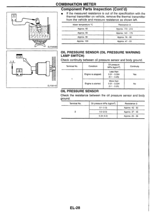 193
193 194
194 195
195 196
196 197
197 198
198 199
199 200
200 201
201 202
202 203
203 204
204 205
205 206
206 207
207 208
208 209
209 210
210 211
211 212
212 213
213 214
214 215
215 216
216 217
217 218
218 219
219 220
220 221
221 222
222 223
223 224
224 225
225 226
226 227
227 228
228 229
229