Page 1493 of 2490
Automatic Transmission/Transaxle External Controls - 4.0L NA V8 -
AJ27/3.2L NA V8 - AJ26 - Selector Lever Switch
Removal and Installation
Removal
Installation
1. Disconnect battery ground cable.
Remove the battery cover.
2. Remove the gear shift knob, (44.15.06).
3. Remove the console finisher veneer panel, (76.47.26).
4. Remove the 'J Gate' surroun d for access, (76.25.24).
5. Remove the D to 4 switch.
Press the retaining tangs to release.
1. Fitting a new D to 4 switch is the reverse of the removal
procedure.
2. Connect the battery and fit the battery cover.
Reset the radio and the clock.
Page 1494 of 2490
Automatic Transmission/Transaxle External Controls - 4.0L NA V8 -
AJ27/3.2L NA V8 - AJ26 - Selector Lever Knob
Removal and Installation
Removal
Installation
1. Remove the select or lever knob.
1. Slacken the ferrule, rotate clock-wise.
2. Rotate the knob coun ter-clockwise to remove.
1. Refer to the illustration
1. Fit the knob.
2. Tighten the ferru le to the specified torque figure.
Page 1498 of 2490
19. Inst
all the slide plate.
Install
the four sl
ide plate screws.
20 . Fi
t the gear shift assembly.
Inst
all th
e four nuts.
21 . Asse
mble the cable to the gear shift assembly.
1. Locate the outer cable.
2. Fit and tighten the cable securing nut to the specified torque figure.
22. Adjust, or verify, the cable in accordance with 44.15.07.
23. Further installation is the reve rse of the removal procedure.
24. Connect the battery and fit the battery cover.
Reset the radio an
d the clock.
Page 1512 of 2490
Automatic Transmission/Transaxle External Contro ls - 4.0L SC V8 - AJ26 -
Kickdown Switch
Removal and Installation
Removal
Installation
1. Disconnect the kickdown switch multiplug.
Move the carpet for access.
2. Remove the kickdown switch.
Rotate counter-clockwise.
1. Installation is th e reverse of the re moval procedure.
2. The kickdown switch MUST be adjusted in accordance with
(44.15.38).
Page 1521 of 2490
Automatic Transmission/Transaxle External Contro ls - 4.0L SC V8 - AJ26 -
Selector Lever Knob
Removal and Installation
Removal
Installation
1.
Disconnect the vehicle battery ground lead.
2. Remove the select or lever knob.
1. Slacken the ferrule, rotate clockwise.
2. Rotate the knob coun ter-clockwise to remove.
1. Refer to the illustration.
1. Fit the knob.
2. Refer to the illustration.
Page 1738 of 2490

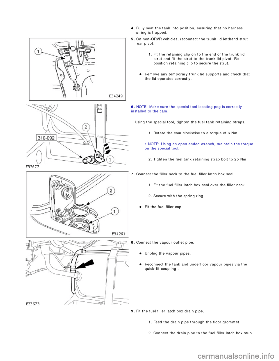
4. Full
y seat the tank into positi
on, ensuring that no harness
wiring is trapped.
5. On non-
ORVR vehicles, reconnec
t the trunk lid lefthand strut
rear pivot.
1. Fit the retaining clip on to the end of the trunk lid strut and fit the strut to the trunk lid pivot. Re-
position retaining clip to secure the strut.
Re
move any temporary trunk lid supports and check that
the lid operates correctly.
6. NOTE
: Make sure the special tool locating peg is correctly
installed to the cam.
Using the special tool, tighten the fuel tank retaining straps.
1. Rotate the cam clockwise to a torque of 6 Nm.
• NOTE: Using an open ended wrench, maintain the torque
on the special tool.
2. Tighten the fuel tank reta ining strap bolt to 25 Nm.
7. Connect the fi
ller neck to the fuel filler latch box seal.
1. Fit the fuel filler latch box seal over the filler neck.
2. Secure with the spring ring
F i
t the fuel filler cap.
8. Connect the vapour outlet pip
e.
Unplug the v
a
pour pipes.
Reconn
ect th
e tank and underfloor vapour pipes via the
quick-fit coupling .
9. Fit the fuel filler latch box drain pipe.
1. Feed the drain pipe th rough the floor grommet.
2. Connect the drain pipe to the fuel filler latch box stub
Page 1743 of 2490

Accelerati
on Control - Accelerator Cable Adjustment
Gen
eral Procedures
1.
Load the Approved Jaguar Diagno stic System with power train
data logger.
2. Connect the Approved Jaguar Diag nostic System to the vehicle.
3. W
ith 'Disable Network Integrity Test - YES/ NO' displayed on
the screen select YES.
4. With new menu displayed on the screen, select ' Engine
Management'.
5. Turn the ignition to ON.
R
emove any previously selected data logger parameters.
6. On data logger select PPS11 an d PPS2 (Pedal demand sensors
1 and 2).
7. On Sedan models only, remove the bulkhead covers on both
sides and the engine compartment rear cover.
8. Cut, remove and discard the ra tchet strap which retains the
throttle cable to the abutment bracket.
9. Ensure there is no tension on the throttle cable by releasing
the throttle cable adjustment nut from the abutment bracket.
10. Record the voltages for both sensors, PPS11 and PPS2.
11. Partially insert the throttle cable adjustment nut into the
abutment bracket.
12. Recheck the voltages for both sensors, PPS11 and PPS2.
13. Where the voltages at step 12 are higher than the voltages
taken at step 10, contin ue to step 15 below.
14. Where the voltages at step 12 are the same as the voltages
taken at step 10, contin ue to step 16 below.
15. Rotate the adjustment nut clockwise (as viewed from the
front of the vehicle) until the same voltages are indicated as in
step 10. Continue to turn thro ugh a part revolution until the
sides of the nut are vertical. Tu rn through a further 90 degrees,
then fully insert the nut into the abutment bracket.
16. Rotate the adjustment nut anti-clockwise (as viewed from the
front of the vehicle) until the indicated voltage starts to
increase. Then rotate the nut clockwise through a part
revolution until the sides are ve rtical. Turn through a further 90
degrees, then fully insert the nut into the abutment bracket.
17. Fit a new ratchet strap to secure the throttle cable adjusting
nut to the abutment bracket.
18. Operate the throttle pedal through 20 full cycles to settle the
cable. Check the voltages now shown, remain the same as in
steps 15 and 16.
19. Check and where necessary adjust the kickdown switch. For
additional information, refer to Section 307
-05A Automatic Transmissi
on/Transaxle External Controls
Sectio
n
307
-05
B
Au
tomatic Transmission/Tra
nsaxle External Controls
.
20
.
On Sedan models only, refit the engine compartment rear
cover and the bulkhead co vers on both sides.
21. Switch the ignition OFF and disconnect the Approved Jaguar
Diagnostic System.
Page 1764 of 2490

Clima
te Control System - General Inform
ation - Manifold Gauge Set Connection
Ge
neral Procedures
Mani
fol
d.
Low Side Pressure Gauge.
High Side Pressure Gauge.
1.
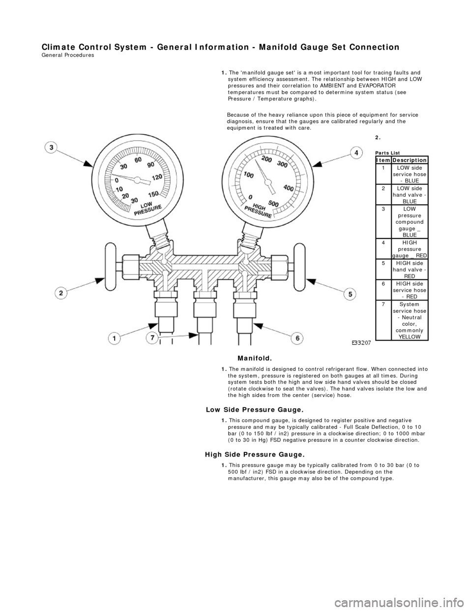
The 'ma
nifold gauge set' is a most important tool for tracing faults and
system efficiency assessment. The relationship between HIGH and LOW
pressures and their correlation to AMBIENT and EVAPORATOR
temperatures must be compared to determine system status (see
Pressure / Temperature graphs).
Because of the heavy reliance upon this piece of equipment for service
diagnosis, ensure that the gauges are calibrated regularly and the
equipment is treated with care.
2.
Parts
List
ItemDescri
ption1LOW side
serv
ice hose
- BLUE
2LOW side
ha
nd valve -
BL
UE3LOW
pres
sure
compound
gauge _ BLUE
4HI GH
pressure
gauge _ RED
5HI GH
side
hand valve -
RED6HI GH
side
service hose
- RED
7Sys t
em
service hose
- Neutral color,
commonly YELLOW
1. The manifold is designed to control refrigerant flow. When connected into
the system, pressure is registered on both gauges at all times. During
system tests both the high and low side hand valves should be closed
(rotate clockwise to seat the valves). The hand valves isolate the low and
the high sides from the center (service) hose.
1. This compound gauge, is designed to register positive and negative
pressure and may be typically calibrate d - Full Scale Deflection, 0 to 10
bar (0 to 150 lbf / in2) pressure in a clockwise direction; 0 to 1000 mbar
(0 to 30 in Hg) FSD negative pressu re in a counter clockwise direction.
1. This pressure gauge may be typically calibrated from 0 to 30 bar (0 to
500 lbf / in2) FSD in a clockwise direction. Depending on the
manufacturer, this gauge may also be of the compound type.