Page 1051 of 2490
The
automatic belt tensioner consists of an idler pulley which is
free to rotate on a bearing, located at the end of a spring-
loaded pivot arm.
The pivot arm can be turned counter-clockwise (viewed from th e front of the engine) for belt removal and installation.
A belt-wear indicator is incorporated on th e rear horizontal face of the pivot arm.
It
em
De
scription
1Bel
t Wear Indicator
2Re
new Belt Indicator
3N
ew Belt Maximum Length
4N
ew Belt Minimum Length
Au
tomatic Belt Tensioner
Page 1053 of 2490

Accessory Drive - Acce
ssory
Drive Belt4.0L NA V8 - AJ27/3.2L NA V8 -
AJ26
Re
moval and Installation
Remov
al
Installation
1.
O
pen the engine compartment and fit paintwork protection
sheets.
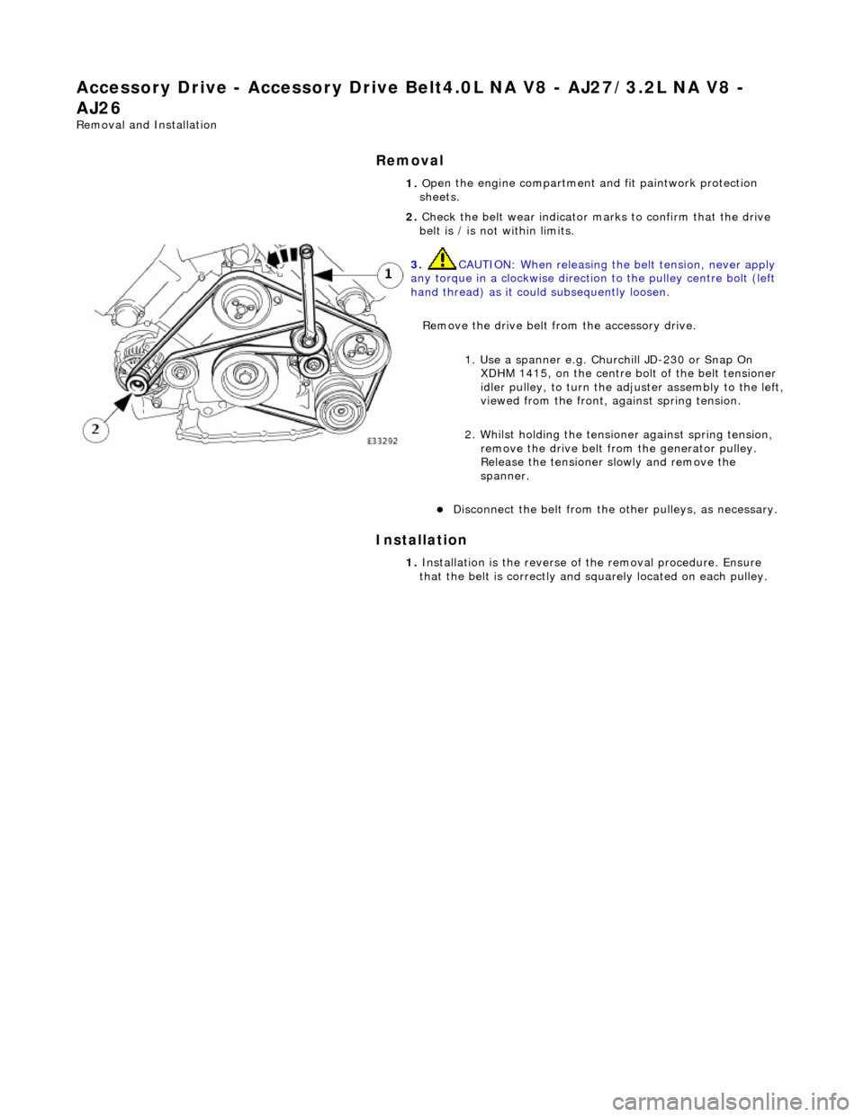
2. Check the belt wear indicator ma rks to confirm that the drive
belt is / is not within limits.
3. CAUTI
ON: When releasing the
belt tension, never apply
any torque in a clockwise direction to the pulley ce ntre bolt (left
hand thread) as it could subsequently loosen.
Remove the drive belt fro m the accessory drive.
1. Use a spanner e.g. Churchill JD-230 or Snap On XDHM 1415, on the centre bo lt of the belt tensioner
idler pulley, to turn the adju ster assembly to the left,
viewed from the front, against spring tension.
2. Whilst holding the tensioner against spring tension, remove the drive belt from the generator pulley.
Release the tensioner sl owly and remove the
spanner.
D
isconnect the belt from the ot
her pulleys, as necessary.
1. In
stallation is the
reverse of the remova l procedure. Ensure
that the belt is correctly and sq uarely located on each pulley.
Page 1054 of 2490

Accessory Drive - Accessory Drive Belt
4.0L SC V8 - AJ26
Re
mo
val and Installation
Remov
a
l
Installation
1.
Op
en the engine compartment and fit paintwork protection
sheets.
2. Remove the supercharger driv e belt, for access. Refer to
operation 18.50.08.
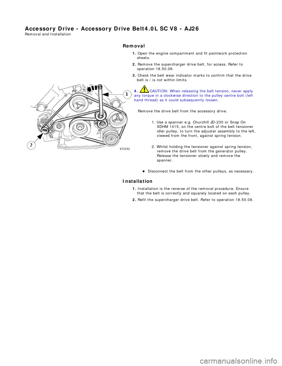
3. Check the belt wear indicator ma rks to confirm that the drive
belt is / is not within limits.
4. CAUTIO
N: When releasing the
belt tension, never apply
any torque in a clockwise direction to the pulley ce ntre bolt (left
hand thread) as it could subsequently loosen.
Remove the drive belt fro m the accessory drive.
1. Use a spanner e.g. Churchill JD-230 or Snap On XDHM 1415, on the centre bo lt of the belt tensioner
idler pulley, to turn the adju ster assembly to the left,
viewed from the front, against spring tension.
2. Whilst holding the tensioner against spring tension, remove the drive belt from the generator pulley.
Release the tensioner sl owly and remove the
spanner.
D i
sconnect the belt from the ot
her pulleys, as necessary.
1. Ins
tallation is the
reverse of the remova l procedure. Ensure
that the belt is correctly and sq uarely located on each pulley.
2. Refit the supercharger drive belt. Refer to operation 18.50.08.
Page 1062 of 2490
Starting System - Starting System
Description and Operation
Manufacturer - NipponDenso
Type - RA1.4.
Weight - 3.75 kg (8.27 lb)
Output - 1.4 kW
Rated Time - 30 seconds
Rotation - Clockwise, viewed from pinion end
The starter is of the pre-engaged type; loca ted at the rear left-side of the engine.
When the starter is operated from the key-switch, the engagement lever moves the pinion into mesh with the engine ring
gear teeth, the electrical contacts within the solenoid complete the high power circuit and the starter motor operates to turn
the engine.
Starter Relay
The starter motor control relay is, relay nu mber 5, located inside the engine compartment enclosure (left side of vehicle
RHD and right side of vehicle on LHD).
Page 1071 of 2490
I
nstallation
8.
The u
pper bolt may be removed (a
fter loosening) using a 3/8"
square drive 13 mm socket, ex tensions and U.J as shown.
1. Installation is the reverse of the removal procedure. Tighten
the starter motor securing bolts to 38-48 Nm.
2. Refit the steering rack as detail ed in Operation 57.10.01. Refill
the reservoir with the reco mmended fluid and bleed the
steering system.
3. Lower the ramp. Remove the protection sheets and close the
engine compartment cover.
4. Connect the battery and fit the battery cover.
R
eset the radio informat
ion and the clock.
Page 2
of 2
Page 1158 of 2490

The fuel fil
ler cap is the same as
that used on non-ORVR systems.
The check valve assembly is a push fit into the end of the fuel filler tube and is accessible with the evaporative flange
removed. The valve has a light spring load ing and opens under the inflow of fuel.
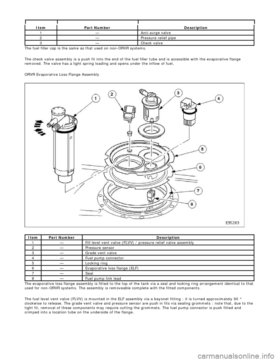
ORVR Evaporative Loss Flange Assembly
The evaporative loss flange assembly is fitted to the top of the tank via a seal and locking ring arrangement identical to that
used for non-ORVR systems. The assembly is re moveable complete with the fitted components.
The fuel level vent valve (FLVV) is mounted in the ELF assembly via a bayonet fitting : it is turned approximately 90 °
clockwise to release. The grade vent valve and pressure sensor are push in fits via sealing gromme ts : note that, due to the
tight fit, removal of these components may require cutting the grommets. The fuel pump connector is push fitted and
crimped into a location tube on the underside of the flange.
It e
m
Par
t
Number
De
scr
iption
1—An
ti-s
urge valve
2—Pressure rel
i
ef pipe
3—Check v
a
lve
It
e
m
Par
t
Number
De
scr
iption
1—Fi
ll
level vent valve (FLVV) /
pressure relief valve assembly
2—Pres
sure
sensor
3—Grade vent
valve
4—Fue
l
pump connector
5—Lockin
g rin
g
6—Evaporative loss flange (ELF)
7—Seal
8—F
u
el pump link lead
Page 1173 of 2490

Evapor
ative Emissions - Fuel Va
por Vent Valve Housing Seal
Remov
al and Installation
Re
moval
• NO
TE: The Removal and Installation procedur
es below show one type of flange but are applicable to the other evaporative loss systems
described.
Special To
ol(s)
Lock
Ring Wrench - Fuel Tank Flange
412-070 (JD 174)
1. Remove battery. Refer to 86.15.01.
2. WARNING: BEFORE PROCEEDING, IT IS ESSENTIAL THAT THE
WARNING NOTES GIVEN IN SECTIO N 100-00 (UNDER THE HEADING
'SAFETY PRECAUTIONS') ARE READ AND UNDERSTOOD.
Remove fuel tank assembly for access. Refer to operation 19.55.01.
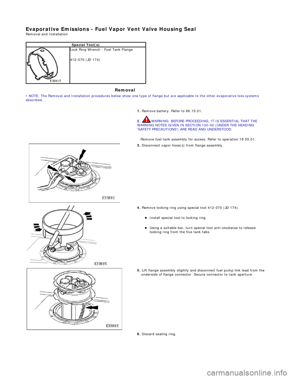
3. Discon
nect vapor hose(s) from flange assembly.
4. Remov
e locking ring using special tool 412-070 (JD 174).
Insta
ll special tool to locking ring.
Usi
ng a suitable bar, turn special tool anti-clockwise to release
locking ring from the five tank tabs.
5. Lift
flange assembly slightly and disconnect fuel pump link lead from the
underside of flange connector. Secure connector to tank aperture.
6. Discard sealing ring.
Page 1174 of 2490
Installation
1.
Insta ll n
ew sealing ring. Make sure it is seated correctly.
2. Connect fuel pump link lead to flange connector.
3. Align and install evaporative loss flange. Make sure sealing ring remains
correctly seated.
4. Insta ll a
nd
fully seat
locking ring
using the
special tool.
Insta ll
special
tool with
bar t
o
locking
ring.
Turn
clock w
ise
until
raised
tabs on
locking
ring locate
against
the fixed
tabs on
the tank.
5. Connect vapor hose(s).
6. Install fuel tank. Refer to operation 19.55.01.
7. Install battery. Refer to 86.15.01 and 86.15.15.
8. Carry out a leak test of the evaporative emissions system.