Page 1862 of 2490
Clock - Clock
Diagnosis and Testing
Tests Using the Portable Diagnostic Unit
Refer to PDU User Guide
The complexity of the electronics involved with the various Electronic Control Modules and the two multiplexed
communication networks, preclude the use of workshop general electrical test equipment. Therefore, reference should be
made to the PDU User Guide for detailed in structions on testing the clock circuit.
The PDU systematically tests an d analyses the clock and the electrucal connections to it.
Where a fault involving the clock is indicated by the PDU, befo re replacing the clock, some basic diagnostic methods may be
necessary to confirm that connections are good and that wiring is not damaged.
Page 1863 of 2490
Clock - Clock
Removal and Installation
Removal
Installation
1.
Disconnect battery ground cable; refer to 86.15.19.
2. Remove fascia center vent assembly; refer to 82.20.38.
3. Remove clock from fascia center vent assembly.
Displace clock retaining tangs and remove clock.
1. Installation is reverse of removal.
Page 1877 of 2490
Battery, Mounting and Cables - Battery Connect
General Procedures
1.
NOTE: Whether one, or both, cables are disconnected, a
minimum of 30 seconds MUST elapse between disconnection of
the FIRST cable and reconnection of the LAST cable. A clean final
connection must be made; do not allow temporary contact.
Connect the batter y terminal(s).
2. Reset the clock.
3. Enter the radio security code. If necessary, refer to the Sound
System Handbook.
Page 1893 of 2490

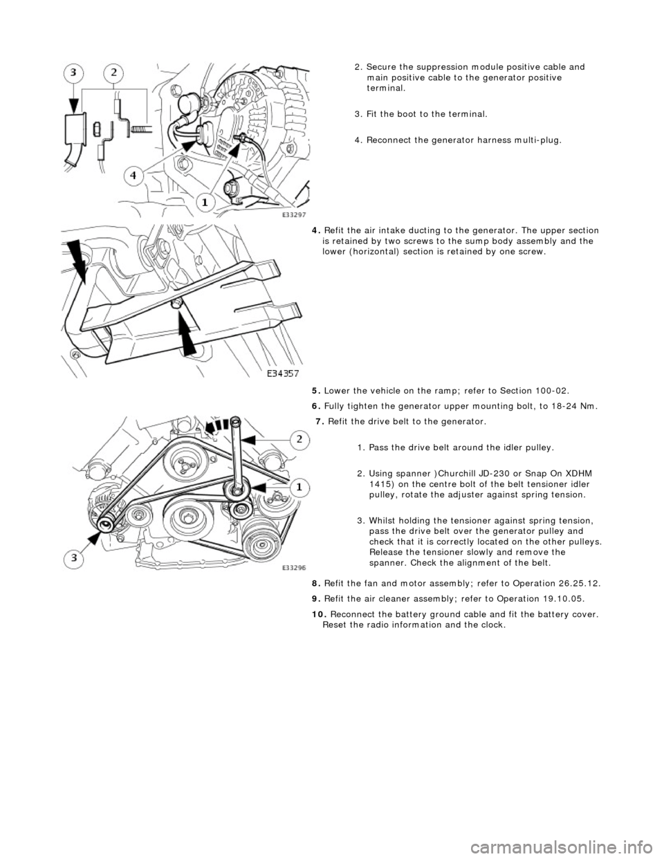
2. Secure the suppression module positive cable and
main positive cable to the generator positive
terminal.
3. Fit the boot to the terminal.
4. Reconnect the generator harness multi-plug.
4. Refit the air intake ducting to the generator. The upper section
is retained by two screws to the sump body assembly and the
lower (horizontal) section is retained by one screw.
5. Lower the vehicle on the ramp ; refer to Section 100-02.
6. Fully tighten the generator upper mounting bolt, to 18-24 Nm.
7. Refit the drive belt to the generator.
1. Pass the drive belt around the idler pulley.
2. Using spanner )Churchill JD-230 or Snap On XDHM 1415) on the centre bolt of the belt tensioner idler
pulley, rotate the adjuster against spring tension.
3. Whilst holding the tensioner against spring tension, pass the drive belt over the generator pulley and
check that it is correctly located on the other pulleys.
Release the tensioner slowly and remove the
spanner. Check the alignment of the belt.
8. Refit the fan and motor assembly ; refer to Operation 26.25.12.
9. Refit the air cleaner assembly; refer to Operation 19.10.05.
10. Reconnect the battery ground cable and fit the battery cover.
Reset the radio inform ation and the clock.
Page 1898 of 2490
1415) on the centre bolt of the belt tensioner idler
pulley, rotate the adjuster against spring tension.
3. Whilst holding the tensioner against spring tension, pass the drive belt over the generator pulley and
check that it is correctly located on the other pulleys.
Release the tensioner slowly and remove the
spanner. Check the alignment of the belt.
9. Fit the supercharger drive belt tensioner; refer to operation
18.50.24.
10. Fit the supercharger drive belt ; refer to operation 18.50.08.
11. Refit the fan and motor asse mbly; refer to Operation
26.25.12.
12. Refit the air cleaner assembly; refer to Operation 19.10.05.
13. Reconnect the battery ground cable and fit the battery cover.
Reset the radio inform ation and the clock.
Page 1907 of 2490
Audio Unit - Capacitor
Removal and Installation
Removal
Installation
1. Disconnect the batt ery ground cable.
Remove the battery cover.
2. Raise the vehicle on a ramp.
3. Remove the suppr ession module.
1. Disconnect the multi-plug from the mounting bracket clip.
2. Disconnect the multi-plug.
3. Remove the bolts which secure the suppression module to the mounting bracket.
4. Remove the su ppression module.
1. Installation is th e reverse of the re moval procedure.
2. Reconnect the battery ground cable and fit the battery cover.
Reset the radio inform ation and the clock.
Page 1912 of 2490
Speakers - A-Pillar Tweeter Speaker LH
Removal and Installation
Removal
Installation
1.
Remove passenger side cantrail and upper 'A' post trim pad;
refer to 76.13.19.
2. Remove tweeter from trim.
Rotate tweeter clockwise to align cut-outs with locating
pegs.
Remove tweeter.
1. Installation is a reversal of the removal procedure.
Page 1913 of 2490
Speakers - A-Pillar Tweeter Speaker RH
Removal and Installation
Removal
Installation
1.
Remove driver side cantrail and upper 'A' post trim pad; refer
to 76.13.20.
2. Remove tweeter from trim.
Rotate tweeter clockwise to align cut-outs with locating
pegs.
Remove tweeter.
1. Installation is a reversal of the removal procedure.