Page 2179 of 2490

Glass, Frames and Mechanisms - Glass, Frames and Mechanisms
Description and Operation
Fixed Glass
The 5 mm thick laminated and tinted glas s windshield is supplied with a moulded rubber seal and stainless trim.The inner
face of the glass adjacent to the seal is directly bonded to the windshield aperture flange, to form a stressed member of the
bodyshell. The 4 mm thick toughened and tinted glass backlight which is similarly bonded to the BIW, incorporates a
heating element and a mounting for the high level stop lamp. The 5 mm tempered and tinted glass quarter light which is
supplied as a complete assembly with stainless trim and seals, is directly bonded to the BIW aperture flanges.
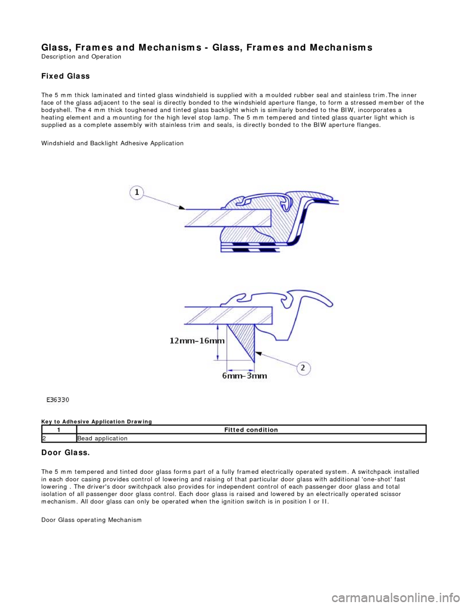
Windshield and Backlight Adhesive Application
Key to Adhesive Application Drawing
Door Glass.
The 5 mm tempered and tinted door glass forms part of a fully framed electrically operated system. A switchpack installed
in each door casing provides control of lowering and raising of that particular d oor glass with additional 'one-shot' fast
lowering . The driver's door switchpack also provides for independent control of each passenger door glass and total
isolation of all passenger door glass control. Each door glas s is raised and lowered by an electrically operated scissor
mechanism. All door glass can only be operated wh en the ignition switch is in position I or II.
Door Glass operating Mechanism
1Fitted condition
2Bead application
Page 2186 of 2490
Glass, Frames and Mechanisms - Front Door Window Regulator and Motor
Removal and Installation
Removal
1. Ensure that door glass is in fully up position.
2. Remove battery cover and disc onnect ground cable from
battery terminal. Refer to 86.15.19.
3. Remove casing/armrest asse mbly from door. Refer to
76.34.01.
4. Remove water shedder carefu lly guiding harness through
penetration, and place adhesive face down on clean polythene
sheet.
5. Position PVC inner weat hershield for access.
6. Remove front door modu le. Refer to 86.80.34.
7. Using linen tape, secure to p of glass to door frame.
8. Disconnect harness mult iplug from lift motor.
9. Slacken and remove screws and nuts securing lift motor to
door.
10. Mark position of door glass gu ide securing screws and slacken and remove screws.
11. Separate motor/regulator assembly from glass, lower into
bottom of door and remove assembly from door.
Page 2191 of 2490

Glass, Frames and Mechanisms - Rear Door Window Glass
Removal and Installation
Removal
1. Remove battery cover and disc onnect ground cable from
battery terminal. Refer to 86.15.19.
2. Remove door casing/armrest as sembly for access. Refer to
76.34.04
3. Remove water shedder carefu lly guiding harness through
penetration, and place adhesive face down on clean polythene
sheet.
4. Position PVC weathe rshield for access.
5. Remove rear door module. Refer to 86.80.33.
6. Using linen tape, secure top of door glass to door frame.
7. Remove rear door glass lift motor. Refer to 86.25.09.
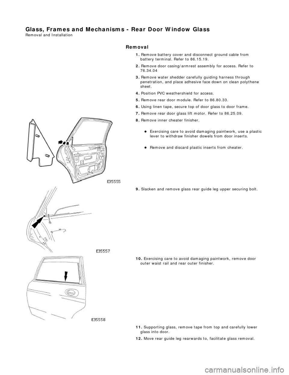
8. Remove inner cheater finisher.
Exercising care to avoid dama ging paintwork, use a plastic
lever to withdraw finisher dowels from door inserts.
Remove and discard plasti c inserts from cheater.
9. Slacken and remove glass rear guide leg upper securing bolt.
10. Exercising care to avoid damaging paintwork, remove door
outer waist rail and rear outer finisher.
11. Supporting glass, remove tape from top and carefully lower
glass into door.
12. Move rear guide leg rearwards to, facilitate glass removal.
Page 2192 of 2490
Installation
13. Withdraw glass upwards through aperture and out via
outboard side of frame.
1. Position glass in aperture.
2. Locate leading edge of glass in seal of front channel.
3. Engage lower rear corner of glas s in seal at top of rear guide
leg.
4. Carefully lower glass into door , ensuring that seals are not
deformed into channels.
Page 2195 of 2490
Glass, Frames and Mechanisms - Rear Door Window Regulator and Motor
Removal and Installation
Removal
1. Ensure that door glass is in fully up position.
2. Remove battery cover and disc onnect ground cable from
battery terminal. Refer to 86.15.19.
3. Remove casing/armrest asse mbly from door. Refer to
76.34.01.
4. Remove water shedder carefu lly guiding harness through
penetration, and place adhesive face down on clean polythene
sheet.
5. Position PVC inner weat hershield for access.
6. Remove rear door module. Refer to 86.80.34.
7. Using linen tape, secure to p of glass to door frame.
8. Disconnect harness mult iplug from lift motor.
9. Slacken and remove screws and nuts securing lift motor to
door.
10. Mark position of door glass gu ide securing screws and slacken and remove screws.
11. Separate motor/regulator assembly from glass, lower into
bottom of door and remove assembly from door.
Page 2235 of 2490
Instrument Panel and Console - Glove Compartment
Removal and Installation
Removal
Installation
1.
Open glovebox.
2. Supporting the glovebox, slac ken and remove the four top
securing screws.
3. Slacken and remove the two glovebox lower outer securing
screws.
4. Withdraw glovebox for access and disconnect the two
illumination harness connectors.
5. Remove glovebox from vehicle.
1. Position glovebox for access and connect illumination harness.
2. Position and fully seat glovebox.
3. Fit but do not tighten the lower securing screws.
4. Fit and fully tighten the upper securing screws.
5. Close glovebox lid.
6. Fully tighten the lower securing screws.
Page 2240 of 2490
Instrument Panel and Console - Instrument Cluster Finish Panel Bezel
Removal and Installation
Removal
1. Adjust steering column to full y extended and lowered position.
2. Remove battery cover and disc onnect ground cable from
battery terminal. Refer to 86.15.19.
3. Remove veneer from instrument panel. Refer to 76.47.24.
4. Using a small screwdriver, de press fog lamp switch upper
retaining tang and release sw itch from gauge surround.
5. Position fog lamp switch fo r access, disconnect harness
multiplug and remove switch.
6. Using a small screwdriver, depress trip keyboard upper
retaining tang and release ke yboard from gauge surround.
7. Position trip keyboard for ac cess and disconnect harness
multiplug.
Page 2242 of 2490

Instrument Panel and Console - Instrument Panel
Removal and Installation
Removal
1. Turn ignition switch to position II.
2. Motor driver and front passenger seats rearward.
3. Position steering wheel in stra ight ahead position and fully
lower and extend steering column.
4. Turn ignition switch to position O.
5. Remove battery cover and disc onnect ground cable from
battery terminal. Refer to 86.15.19.
6. Remove 'J' gate finish er. Refer to 76.25.24.
7. Remove 'J' gate finisher retain ing panel. Refer to 76.25.26.
8. Remove centre console veneer panel. Refer to 76.47.26.
9. Disconnect and remove radio.
10. Remove centre console switch module. Refer to 86.80.32.
11. Remove centre console. Refer to 76.25.01.
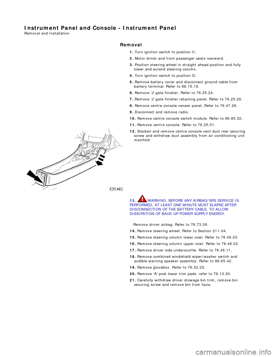
12. Slacken and remove centre cons ole vent duct rear securing
screw and withdraw duct assemb ly from air conditioning unit
manifold.
13. WARNING: BEFORE ANY AIRBAG/SRS SERVICE IS
PERFORMED, AT LEAST ONE MINUTE MUST ELAPSE AFTER
DISCONNECTION OF THE BATTERY CABLE, TO ALLOW
DISSIPATION OF BACK-UP POWER SUPPLY ENERGY.
Remove driver airbag. Refer to 76.73.39.
14. Remove steering wheel. Refer to Section 211-04.
15. Remove steering column lo wer cowl. Refer to 76.46.03.
16. Remove steering column u pper cowl. Refer to 76.46.02.
17. Remove driver side unders cuttle. Refer to 76.46.11.
18. Remove combined windshield wiper/washer switch and
audible warning speaker assembly. Refer to 86.65.42.
19. Remove glovebox. Refer to 76.52.03.
20. Remove 'A' post lower trim pads. refer to 76.13.30.
21. Carefully withdraw driver stowage bin trim, remove bin
securing screw and remove bin from facia.