1998 JAGUAR X308 ESP
[x] Cancel search: ESPPage 663 of 2490

2. Fit the camshaft caps to their respective locations (5 to 9 from the front) and in the correct orientation
(arrow to front of engine).
3. Fit and tighten the cap securing bolts. Tighten evenly,
in stages, to 9 - 11 Nm.
3. Fit the camshaft locking tool 303 - 530 (fitted for following
operation) align the camshaft as necessary.
4. Refit Exhaust Camshaft Sprocket . Refer to Operation 12.65.73.
5. With the camshaft (303 - 530) and crankshaft (303 - 531)
setting tools removed, after the previous operation, adjust the
valve clearances on the exhaus t camshaft. refer to Operation
12.29.48.
6. Move the engine compartment co ver from the service position
and connect the gas struts.
7. Remove the paint protection sheets and close the cover.
8. Connect the battery and fit the battery cover.
Refer to the Battery Reconnection Procedure 86.15.15.
Page 701 of 2490

1. Fit the camshaft to position in the cylinder head, with the timing flats uppermost.
2. Fit the camshaft caps to their respective locations (0 to 4 from the front) and in the correct orientation
(arrow to front of engine).
3. Fit and tighten the cap securing bolts. Tighten evenly,
in stages, to 9 - 11 Nm.
3. Fit the camshaft locking tool 303 - 530 (fitted for following
operation) align the camshaft as necessary.
4. Refit the VVT Unit to the A-Bank. Refer to Operation 12.65.71.
This also includes the VVT Bu sh Carrier Assembly, Primary
Chain and Tensioner.
5. With the camshaft (303 - 530) and crankshaft (303 - 531)
setting tools removed, after the previous operation, adjust the
valve clearances on the inlet camshaft. refer to Operation
12.29.48.
6. Refit the Timing Cover. Re fer to Operation 12.65.01.
7. Move the engine compartment co ver from the service position
and connect the gas struts.
8. Remove the paint protection sheets and close the cover.
9. Connect the battery and fit the battery cover.
Refer to the Battery Reconnection Procedure 86.15.15.
Page 703 of 2490

1.
Fit the camshaft to position in the cylinder head, with
the timing flats uppermost.
2. Fit the camshaft caps to their respective locations (0 to 4 from the front) and in the correct orientation
(arrow to front of engine).
3. Fit and tighten the cap securing bolts. Tighten evenly,
in stages, to 9 - 11 Nm.
3. Fit the camshaft locking tool 303 - 530 (fitted for following
operation) align the camshaft as necessary.
4. Refit the VVT Unit to the A-Bank. Refer to Operation 12.65.70.
This also includes the VVT Bu sh Carrier Assembly, Primary
Chain and Tensioner.
5. With the camshaft (303 - 530) and crankshaft (303 - 531)
setting tools removed, after the previous operation, adjust the
valve clearances on the inlet camshaft. refer to Operation
12.29.48.
6. Refit the Timing Cover. Re fer to Operation 12.65.01.
7. Move the engine compartment co ver from the service position
and connect the gas struts.
8. Remove the paint protection sheets and close the cover.
9. Connect the battery and fit the battery cover.
Re
fer to the Battery Reconnection Procedure 86.15.15.
Page 765 of 2490

sprocket, B-Bank.
Reposition the sprocket (and the VVT unit) for the most
advantageous position for use of the tool.
Remove the tool.
2. Refit the primary timing chain, B-Bank.
1. Fit the primary chain over the crankshaft sprocket and the VVT unit sprocket. There must be no slack on
the drive side of the primary chain and the VVT unit
must not be rotate d on the camshaft.
Slide the VVT and exhaust sprocket fully rearwards onto
the respective camshafts.
3. Fit the primary chain tensioner blade.
1. Position the tensioner blade to the cylinder block.
2. Fit the retaining / pivot bolt and tighten it to 12 - 16 Nm.
4. Refit the primary chain tensione r assembly. Refer to Operation
12.65.55 in this Section.
Use a wedge 303 - 533 (or two if required) between the
primary chain tensioner and te nsioner blade, to take up
the slack in the chain.
5. Tighten the exhaust camshaft sprocket securing bolt.
1. Fit the chain tensioner tool 303 - 532 to the sprocket holes.
1. Apply force to the tool in an anti-clockwise direction
to tension the chain on its drive side.
2. Whilst applying the opposing force to the sprocket
Page 775 of 2490

camshaft sprocket, Bank 2.
Reposition the sprocket to the most advantageous position for use of the tool.
Remove the tool.
2. Install the primary timi ng chain, Bank 2.
1. Install the primary chain over the crankshaft sprocket and the intake camshaft sp rocket. There must be no
slack on the drive side of the primary chain and the
sprockets should not be rotated on the camshafts (or
the tensioning tool may not fit).
Slide the camshaft sprocket s fully rearwards onto the
respective camshafts.
3. Install the primary ch ain tensioner blade.
1. Position the tensioner blade to the cylinder block.
2. Install the retaining / pivo t bolt and tighten it to 12-
16 Nm.
4. Install the primary chain te nsioner assembly. Refer to
Operation 12.65.55.
Use a wedge 303-533 (or two if required) between the
primary chain tensioner and te nsioner blade, to take up
the slack in the chain.
5. Tighten the exhaust camshaft sprocket securing bolt.
1. Install the chain tensioner tool 303-532 to the sprocket holes.
Apply force to the tool in an anti-clockwise direction to
tension the chain on its drive side.
Page 1023 of 2490

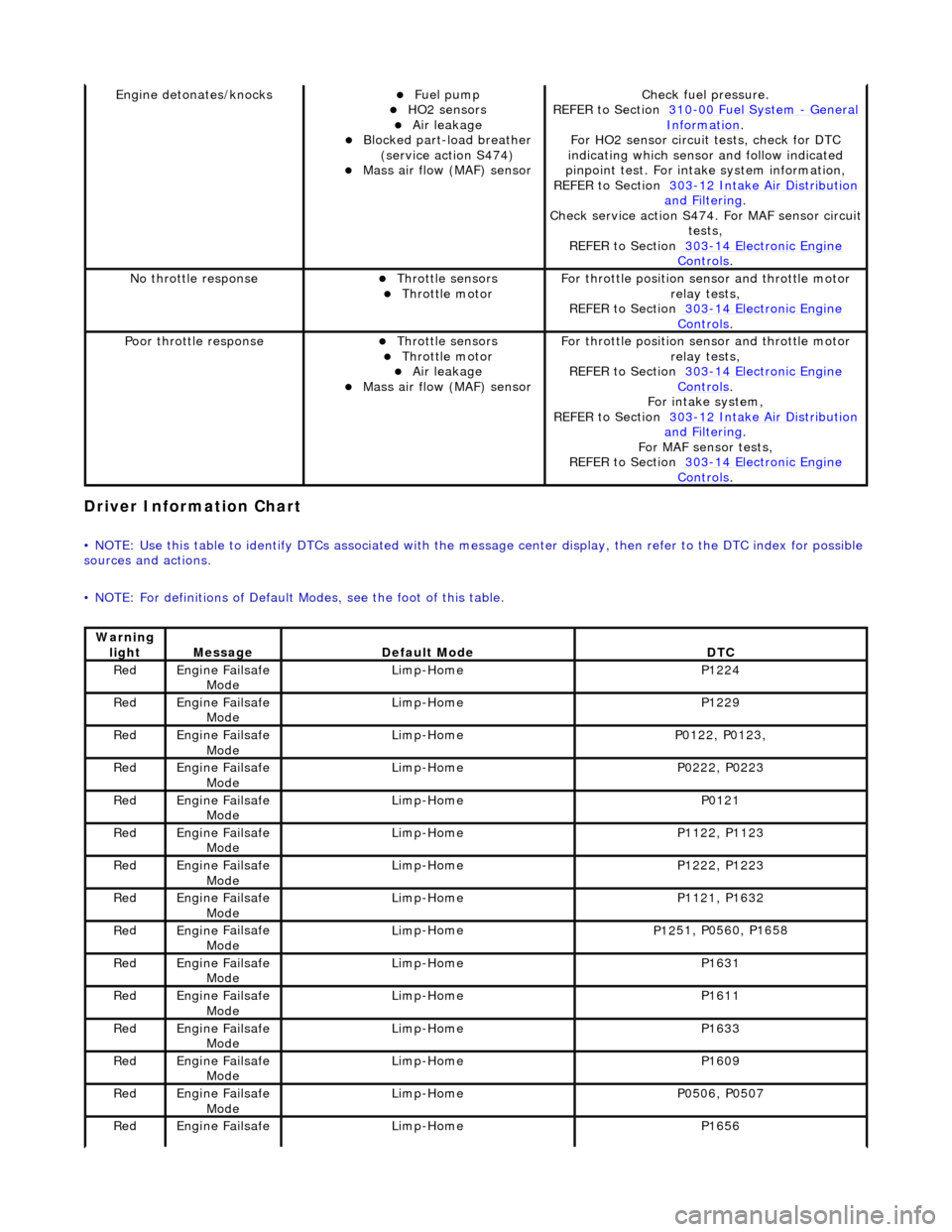
Driver Informa
tion Chart
•
NOTE: Use this table to identify DTCs associated with the me
ssage center display, then refer to the DTC index for possible
sources and actions.
• NOTE: For definitions of Default Modes, see the foot of this table.
Engine deton
ates/knocks
Fue
l pump
HO2 sensors Air leakage Blocked part-load breather
(
service action S474)
Mass ai
r flow (MAF) sensor
Chec
k fuel pressure.
REFER to Section 310
-00
Fuel System
- Gen
eral
Informati
on
.
F
or HO2 sensor circuit
tests, check for DTC
indicating which sensor and follow indicated
pinpoint test. For intake system information,
REFER to Section 303
-1
2 Intake Air Distribution
and F
iltering
.
Check service
action S474. For MAF sensor circuit
tests,
REFER to Section 303
-14 Elec
tronic Engine
Controls.
No
throttle response
Throttl
e sensors
Throttl
e motor
F
or throttle position se
nsor and throttle motor
relay tests,
REFER to Section 303
-14 Elec
tronic Engine
Controls.
Poor throttle responseThrottl
e sensors
Throttl
e motor
Air leakage Mass ai
r flow (MAF) sensor
F
or throttle position se
nsor and throttle motor
relay tests,
REFER to Section 303
-14 Elec
tronic Engine
Controls.
Fo
r intake system,
REFER to Section 303
-1
2 Intake Air Distribution
and F
iltering
.
For MAF
sensor tests,
REFER to Section 303
-14 Elec
tronic Engine
Controls.
Warning
lightMess
age
De
fault Mode
DT
C
Re
d
Engine
Failsafe
Mode
Lim
p-Home
P1224
Re
d
Engine
Failsafe
Mode
Lim
p-Home
P1229
Re
d
Engine
Failsafe
Mode
Lim
p-Home
P01
22, P0123,
Re
d
Engine
Failsafe
Mode
Lim
p-Home
P02
22, P0223
Re
d
Engine
Failsafe
Mode
Lim
p-Home
P0121
Re
d
Engine
Failsafe
Mode
Lim
p-Home
P11
22, P1123
Re
d
Engine
Failsafe
Mode
Lim
p-Home
P12
22, P1223
Re
d
Engine
Failsafe
Mode
Lim
p-Home
P11
21, P1632
Re
d
Engine
Failsafe
Mode
Lim
p-Home
P12
51, P0560, P1658
Re
d
Engine
Failsafe
Mode
Lim
p-Home
P1631
Re
d
Engine
Failsafe
Mode
Lim
p-Home
P1611
Re
d
Engine
Failsafe
Mode
Lim
p-Home
P1633
Re
d
Engine
Failsafe
Mode
Lim
p-Home
P1609
Re
d
Engine
Failsafe
Mode
Lim
p-Home
P05
06, P0507
Re
d
Engine
Failsafe
Lim
p-Home
P1656
Page 1080 of 2490

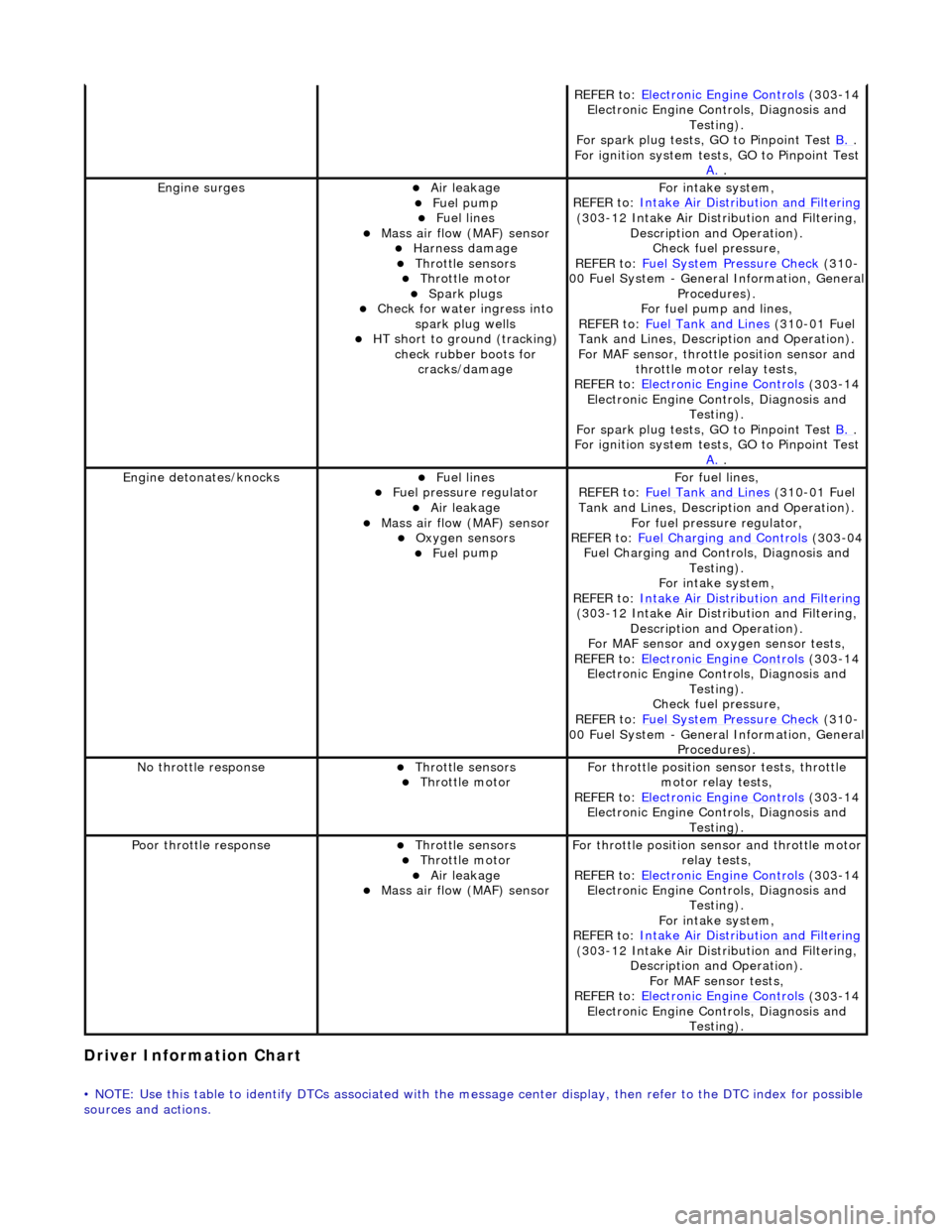
Driver Information
Chart
•
NOTE: Use this table to identify DTCs associated with the me
ssage center display, then refer to the DTC index for possible
sources and actions.
REF E
R to:
Electronic Engine Controls
(303
-14
Electronic Engine Co ntrols, Diagnosis and
Testing).
For spark plug tests, GO to Pinpoint Test B.
.
For ign i
tion system tests, GO to Pinpoint Test
A.
.
Engine s
urges
Air leakage
Fue
l
pump
Fue
l
lines
Mass ai
r fl
ow (MAF) sensor
Harness damage Throttl
e
sensors
Throttl
e
motor
Spark plugs
Check fo
r water ingress into
spark plug wells
HT short to ground (tracking) check rubber
boots for
cracks/damage
Fo r
intake system,
REFER to: Intake Air Distribution and Filtering
(30 3
-12 Intake Air Distribution and Filtering,
Description and Operation). Check fuel pressure,
REFER to: Fuel System Pressure Check
(310
-
00 Fuel System - Genera l Information, General
Procedures).
For fuel pump and lines,
REFER to: Fuel Tank and Lines
(310
-01 Fuel
Tank and Lines, Description and Operation).
For MAF sensor, throttle position sensor and
throttle motor relay tests,
REFER to: Electronic Engine Controls
(303
-14
Electronic Engine Co ntrols, Diagnosis and
Testing).
For spark plug tests, GO to Pinpoint Test B.
.
For ign i
tion system tests, GO to Pinpoint Test
A.
.
Engine detonates/k
nocks
Fue
l
lines
F
u
el pressure regulator
Air leakage
Mass air fl
ow (MAF) sensor
O
xygen senso
rs
Fue
l
pump
F
o
r fuel lines,
REFER to: Fuel Tank and Lines
(310
-01 Fuel
Tank and Lines, Description and Operation).
For fuel pressure regulator,
REFER to: Fuel Charging and Controls
(303
-04
Fuel Charging and Controls, Diagnosis and Testing).
For intake system,
REFER to: Intake Air Distribution and Filtering
(30 3
-12 Intake Air Distribution and Filtering,
Description and Operation).
For MAF sensor and oxyg en sensor tests,
REFER to: Electronic Engine Controls
(303
-14
Electronic Engine Co ntrols, Diagnosis and
Testing).
Check fuel pressure,
REFER to: Fuel System Pressure Check
(310
-
00 Fuel System - Genera l Information, General
Procedures).
No t
hrottle response
Throttl
e
sensors
Throttl
e
motor
Fo
r th
rottle position sensor tests, throttle
motor relay tests,
REFER to: Electronic Engine Controls
(303
-14
Electronic Engine Co ntrols, Diagnosis and
Testing).
Poor throttle responseThrottl e
sensors
Throttl
e
motor
Air leakage Mass air fl
ow (MAF) sensor
F
or throttl
e position se
nsor and throttle motor
relay tests,
REFER to: Electronic Engine Controls
(303
-14
Electronic Engine Co ntrols, Diagnosis and
Testing).
For intake system,
REFER to: Intake Air Distribution and Filtering
(30 3
-12 Intake Air Distribution and Filtering,
Description and Operation). For MAF sensor tests,
REFER to: Electronic Engine Controls
(303
-14
Electronic Engine Co ntrols, Diagnosis and
Testing).
Page 1109 of 2490

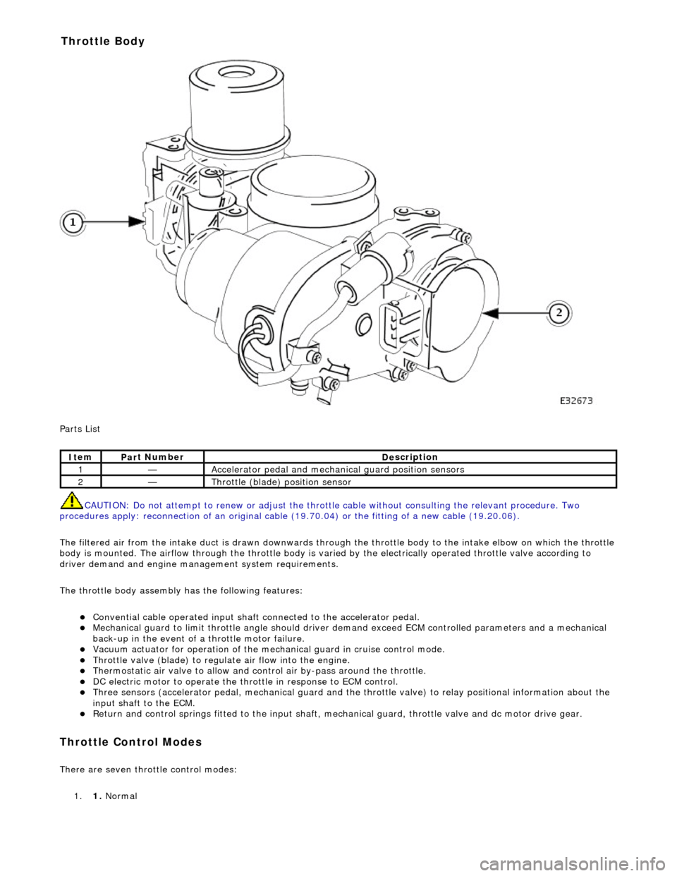
P
arts List
CAUTION: Do not attempt to renew or adjust the throttle cable without consulting the relevant procedure. Two
procedures apply: reconnection of an original cable (19.70.04) or the fitting of a new cable (19.20.06).
The filtered air from the intake duct is drawn downwards through the throttle body to the intake elbow on which the throttle
body is mounted. The airflow through the throttle body is vari ed by the electrically operated throttle valve according to
driver demand and engine mana gement system requirements.
The throttle body assembly has the following features:
Con
vential cable operated input shaft connected to the accelerator pedal.
M
echanical guard to limit throttle angl
e should driver demand exceed ECM co ntrolled parameters and a mechanical
back-up in the event of a throttle motor failure.
Vacuum actuator for operation of the mech anical guard in cru
ise control mode.
Thr
ottle valve (blade) to regula
te air flow into the engine.
Thermostatic air valve to allow and con
t
rol air by-pass around the throttle.
D
C electric motor to operate the thro
ttle in response to ECM control.
Three
sensors (accelerator pedal, mechan
ical guard and the throttle valve) to relay positional information about the
input shaft to the ECM.
R
eturn and control springs fitted to th
e input shaft, mechanical guard, thro ttle valve and dc motor drive gear.
Throttle Cont
rol Modes
There are seven throttle control
modes:
1. 1. Normal
It
em
Par
t Number
De
scription
1—Acce
lerator pedal and mechanic
al guard position sensors
2—Throttl
e (blade)
position sensor
Throttle Body