Page 379 of 2490
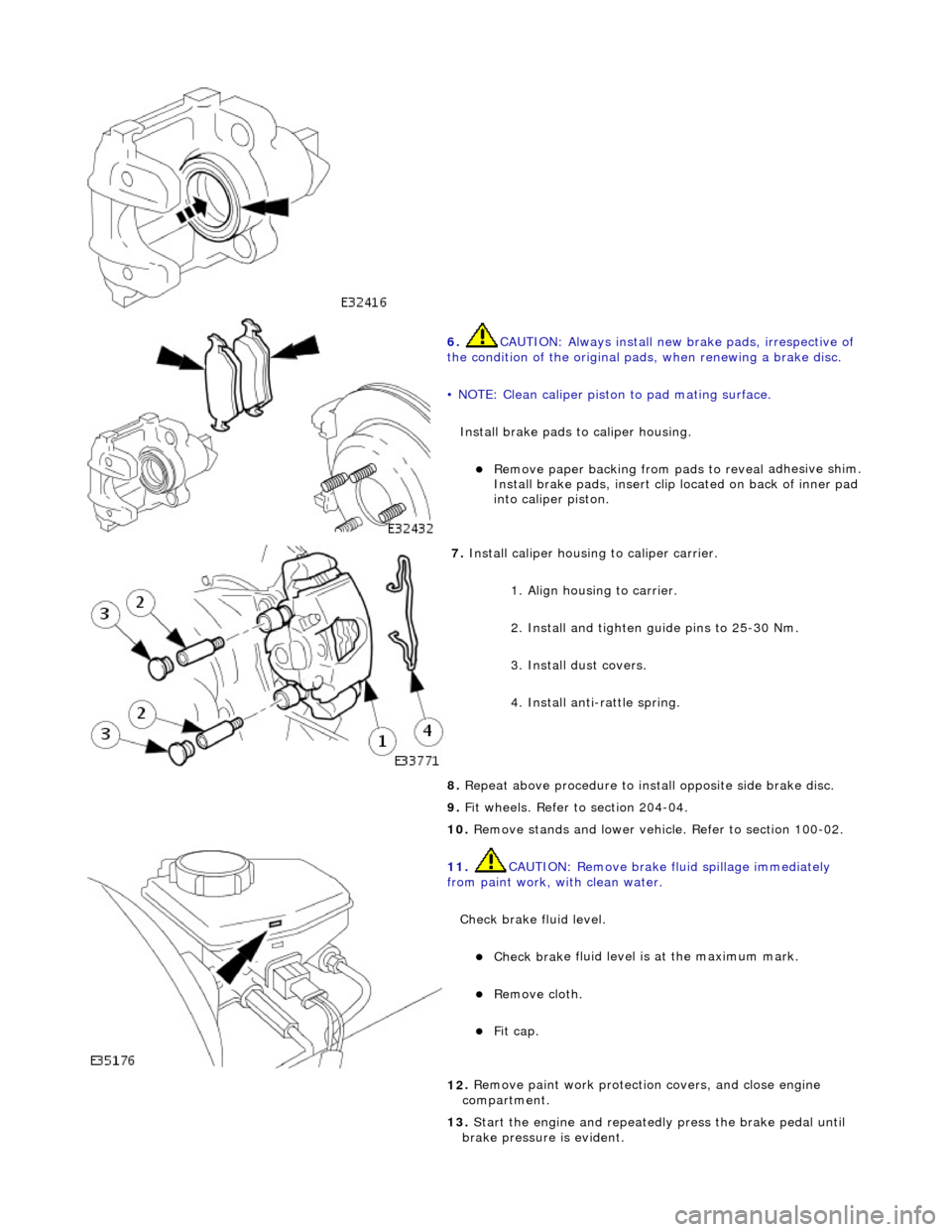
6. CAUTI
ON: Always install new brake pads, irrespective of
the condition of the original pads, when renewing a brake disc.
• NOTE: Clean caliper piston to pad mating surface.
Install brake pads to caliper housing.
Remove paper backing from pads to reveal
adhesive shim.
Install brake pads, in sert clip located on back of inner pad
into caliper piston.
7. Inst
all caliper housing to caliper carrier.
1. Align housing to carrier.
2. Install and tighten gu ide pins to 25-30 Nm.
3. Install dust covers.
4. Install anti-rattle spring.
8. Repeat above procedure to inst all opposite side brake disc.
9. Fit wheels. Refer to section 204-04.
10. Remove stands and lower vehicl e. Refer to section 100-02.
11
.
CAUTION: Remove brake fl uid spillage immediately
from paint work, wi th clean water.
Check brake fluid level.
Check brak
e fluid level is
at the maximum mark.
Re
move cloth.
Fi
t cap.
12
.
Remove paint work protection covers, and close engine
compartment.
13. Start the engine and repeatedly press the brake pedal until
brake pressure is evident.
Page 380 of 2490
Rear Disc
Brake - Brake DiscVehicl
es With: High Performance Brakes
Remo
val and Installation
Remov
a
l
1.
WAR N
INGS:
BRAKE DISCS MUST ALWAYS BE REPLACED IN PAIRS.
BRAKE DUST, IF INHALED CAN DAMAGE YOUR HEALTH.
ALWAYS REMOVE BRAKE DUST USING A VACUUM BRUSH. DO
NOT USE A COMPRESSED-AIR LINE TO DISPERSE BRAKE DUST
INTO THE ATMOSPHERE.
• CAUTIONS:
Replacement of nuts and bolts: Various thread-locking
devices are used on nuts and bolts throughout the vehicle. These
devices restrict the number of ti mes a nut or bolt can be used.
See section 100-00 for information.
The Brembo caliper is aligned to the brake disc when it is
first installed to the vehicle, therefore, care must be taken not to
disturb this alignment. When removing the caliper; remove the
bolts that secure the anchor brac ket to the hub carrier only. DO
NOT loosen any other caliper bolts.
Open engine compartment and fit paint work protection covers
to fenders.
2. Ra
ise rear of vehicle and support
on stands. Refer to section
100-02.
3. Remove rear wheels. Refer to section 204-04.
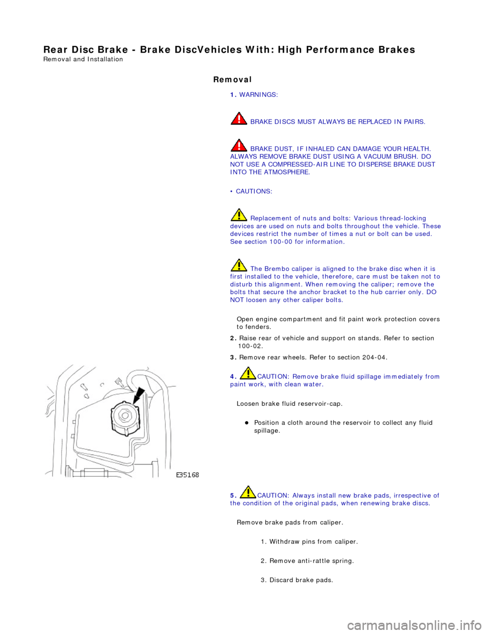
4. CAUTIO
N: Remove brake flui
d spillage immediately from
paint work, with clean water.
Loosen brake fluid reservoir-cap.
Position a cloth around the reser
voir to collect any fluid
spillage.
5. CAUTIO
N: Always install new brake pads, irrespective of
the condition of the original pads, when renewing brake discs.
Remove brake pads from caliper. 1. Withdraw pins from caliper.
2. Remove anti-rattle spring.
3. Discard brake pads.
Page 382 of 2490
In
stallation
10
. R
emove brake dust from calipers, and from area of parking
brake shoes, see WARNING above.
11. Repeat above procedure to remo ve opposite side brake disc.
12. Thoroughly clean the area of both hubs where they mate
against the br ake discs.
1. Inst al
l brake disc to wheel studs.
Make su
re hu
b and brake disc
access holes are aligned.
2. Set the parking brake, refer to operation 70.35.37.
3. Check brake disc run-out. Refer to General Procedures section
206-04.
4. Inst al
l caliper to hub carrier.
Install and tigh
ten bolts to 6
0 Nm.
5. CAUTIONS:
Always install new brake pads, irrespective of the condition
of the original pads, when renewing brake discs.
Retracting the caliper piston may cause the fluid reservoir
to over-flow. Remove brake flui d spillage immediately from paint
work with clean water.
Page 482 of 2490
P a
rts List
The variable ratio rack:
Incorporates teeth
of varying pitch and angle of contact, giving a variable pi
tch circle diameter which is a minimum
at the center of the rack and a maximum at the ends.
R e
duces excessive response to on-center stee
ring inputs during motorway driving.
Causes the steering action to become pro
gressively more
direct as the stee ring wheel is turned from the center
position.
Allows a low n u
mber of turns of the
steering wheel from lock to lock.
Ite
m
Par
t
Number
De
scr
iption
1—Steeri
ng rack
2—Tooth contact an
gle at
center of rack
3—Tooth c o
ntact angle
at ends of rack
Variable Ratio Steering Rack
Page 488 of 2490
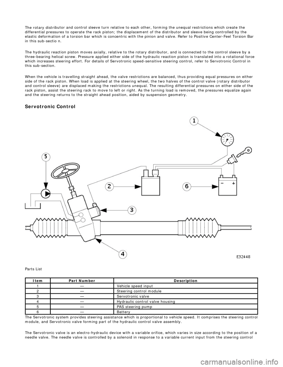
The rotary distri
butor and control sleeve turn relative to ea
ch other, forming the unequal restrictions which create the
differential pressures to operat e the rack piston; the displacement of the di stributor and sleeve being controlled by the
elastic deformation of a torsion bar which is concentric with the pinion and valve. Refer to Positive Center-Feel Torsion Bar
in this sub-sectio n.
The hydraulic reaction piston moves axially, relative to th e rotary distributor, and is connected to the control sleeve by a
three-bearing helical screw. Pressure applied either side of the hydraulic reaction piston is translated into a rotational force
which increases steering effort. For detail s of Servotronic speed-sensitive steering control, refer to Servotronic Control in
this sub-section.
When the vehicle is travelling straight ah ead, the valve restrictions are balanced, thus providing equal pressures on either
side of the rack piston. When load is a pplied at the steering wheel, the two halves of the control valve (rotary distributor
and control sleeve) are displaced making the restrictions unequa l. The resulting differential pressures on either side of the
rack piston, assist the steering rack to mo ve to left or right. As the turning load is removed, the pressures equalize again
and the steering return s to the straight ahead position , aided by suspension geometry.
Serv
otronic Control
P a
rts List
The Servotronic system provides steering assistance which is pr oportional to vehicle speed. It comprises the steering control
module, and Servotronic valve forming part of the hydraulic control valve assembly.
The Servotronic valve is an electro-hydrauli c device with a variable orifice, which varies in size according to the position of a
needle valve. The needle valve is controlled by a solenoid in response to a variable current input from the steering control
Ite
m
Part
Number
Descr
iption
1—Vehi
cl
e speed input
2—Steeri
ng control
module
3—Servotronic valve
4—Hydraulic
control valve housing
5—PAS stee
rin
g pump
6—Batt
ery
Page 489 of 2490
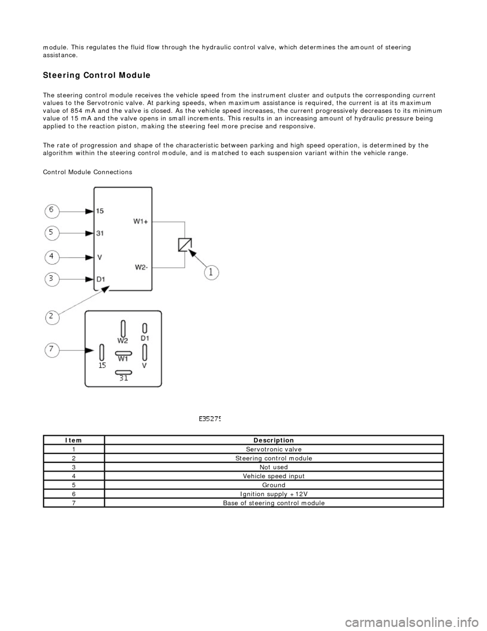
modul
e. This regulates the fluid flow
through the hydraulic control valve, wh ich determines the amount of steering
assistance.
Steering Control Module
The steering control
module re
ceives the vehicle speed from the instrument cluster and outputs the corresponding current
values to the Servot ronic valve. At parking speeds, wh en maximum assistance is required , the current is at its maximum
value of 854 mA and the valve is closed. As the vehicle speed increases, the current progressively decreases to its minimum
value of 15 mA and the valve opens in sma ll increments. This results in an increasing amount of hydraulic pressure being
applied to the reaction piston, making the steering feel more precise and responsive.
The rate of progression and shape of the characteristic between parking and high speed operation, is determined by the
algorithm within the steering control module, and is matched to each suspension variant within the vehicle range.
Control Module Connections
It
em
De
scription
1Servotronic valve
2Steeri
ng control module
3No
t used
4Vehi
cle speed input
5Ground
6Ignition su
pply +12V
7Base of
steering control module
Page 505 of 2490
Steering Column - Steering Column
Description an
d Operation
Stee
ring Wheel
T
he steering wheel assembly incorporates:
The s
peed control switchpack.
The i
n-car entertainment (ICE) switchpack.
The h
orn pad.
The driver ai
r bag module; refer to Section
501
-20A Safety Belt
System
Sectio
n
501
-2
0B Supplemental Restraint
Sy
stem
.
I
CE Switchpack
The
in-car entertainment (ICE) switchpack is installed to the le
ft of the steering wheel center, controlling the ICE functions
and telephone (where fitted). The switchpack overrides the corresponding bu ttons on the ICE control panel and performs
the following functions:
1. 1. Increase the volume of the select ed audio output or telephone.
It
em
Par
t Number
De
scription
1-Spe
ed control switchpack
2-I
CE switchpack
3-Horn pad
4-Air bag lo
cation
It
em
Par
t Number
De
scription
1-Vol
ume increase
2-ICE func
tions/teleph
one mode select
3-Volum
e decrease
4-ICE pres
ets/telephone memory select
Page 516 of 2490
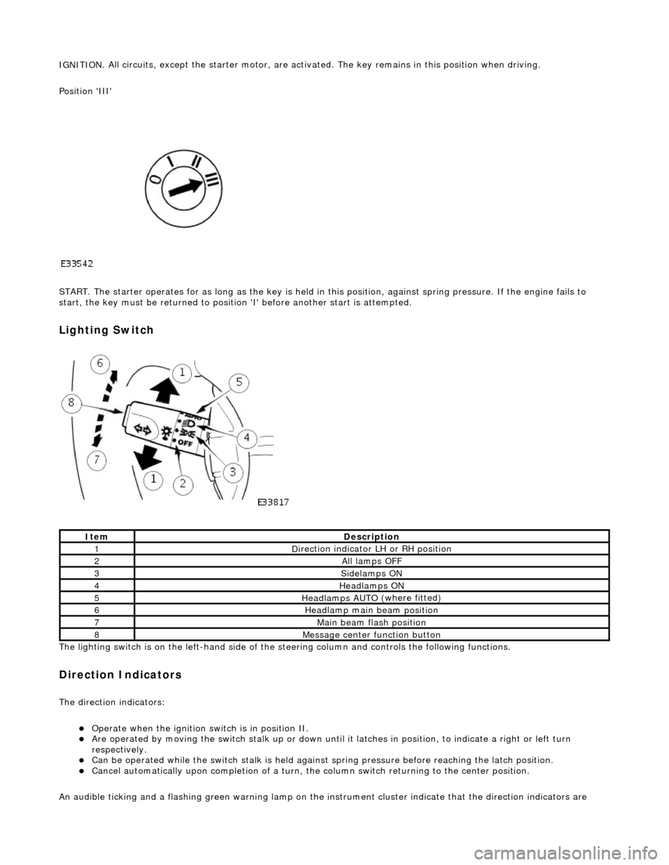
IGNITION.
All circuits, except the star
ter motor, are activated. The key rema ins in this position when driving.
Position 'III'
START. The starter operates for as long as the key is held in this position, ag ainst spring pressure. If the engine fails to
start, the key must be returned to position 'I' befo re another start is attempted.
Lighting Switch
The li
ghting switch is on the left-h
and side of the steering column and controls the following functions.
Direction Indicators
The direction in
dicators:
Operate
when the ignition switch is in position II.
Are operat
ed by movi
ng the switch stalk up or down until it latches in position, to in
dicate a right or left turn
respectively.
Can be o p
erated while the switch stalk is held against
spring pressure before reaching the latch position.
Cancel
automatically upon completion of a turn, the
column switch returning to the center position.
An audible ticking and a flashing green warning lamp on the in strument cluster indicate that the direction indicators are
Ite
m
De
scr
iption
1D
i
rection indicator LH or RH position
2All lamps OFF
3Side
lamps ON
4Headlamps ON
5Headlamps AUT O
(where fitted)
6He
adlam
p main beam position
7Mai
n
beam flash position
8M
e
ssage center function button