Page 1649 of 2490
6.
Connec
t the oxygen sensor multiplugs.
Con
nect the plug(s) to the respective (previously noted)
sensor(s).
Cor
rectly position the multiplu
gs on the mounting bracket.
7. Raise the ramp.
8. Tigh
ten the mounting brac
ket securing bolts.
9. Fit the front muffler; refer to Operation 30.10.18.
10. Lower the ramp.
11. Remove the paintwork protection sheets and close the engine
cover.
Page 1652 of 2490
1. Fit
the oxygen sensor(s).
The downstream sensor is
fitt
ed only for North American
markets.
2. Fit a new gasket to the mani fold mating flange on the
downpipe.
3. Fit
the downpipe catalytic converter.
1. Fit the downpipe assembly to the manifold.
Fit,
but do not fully tighten, the mounting bracket securing
bolts. (Leave loose until the nu ts securing the downpipe to
the exhaust manifold are fitted.)
4. Lower the ramp.
5. Tigh te
n the nuts securing the downpipe flange to the manifold
flange..
6. Connec t
the oxygen sensor multiplugs.
Con
n
ect the plug(s) to the respective (previously noted)
sensor(s).
Cor r
ectly position the multiplu
gs on the mounting bracket.
7. Raise the vehicle on the ramp.
8. Tighten the mounting brac ket securing bolts.
Page 1656 of 2490
5. Connec t
the oxygen sensor multiplugs.
Con
n
ect the plug(s) to the respective (previously noted)
sensor(s).
Cor r
ectly position the multiplu
gs on the mounting bracket.
6. Fi
t the coolant header tank.
1. Reposition the tank and fit the securing nuts.
2. Connect the harness connector
7. Re
fit the centre trim panel and th
e left hand enclosure panel to
the engine compartment.
1. Refit the centre trim panel.
2. Refit the left hand enclosure panel.
8. Raise the ramp.
9. Tighten the mounting brac ket securing bolts.
Page 1660 of 2490
In
stallation
1.
Fit a ne
w gasket to the mani
fold mating flange on the
downpipe.
2. Fit
the downpipe catalytic converter.
1. Fit the downpipe assembly to the manifold.
Fit,
but do not fully tighten, the mounting bracket securing
bolts. (Leave loose until the nu ts securing the downpipe to
the exhaust manifold are fitted.)
3. Lower the ramp.
4. Tigh te
n the nuts securing the downpipe flange to the manifold
flange.
5. Connec t
the oxygen sensor multiplugs.
Con
n
ect the plug(s) to the respective (previously noted)
sensor(s).
Cor r
ectly position the multiplu
gs on the mounting bracket.
6. Fi
t the coolant header tank.
1. Reposition the tank and fit the securing nuts.
2. Connect the harness connector
7. Refit the centre trim panel and th e left hand enclosure panel to
the engine compartment.
Page 1663 of 2490
do
wnpipe.
2. F
it the downpipe catalytic converter.
Fit the down
pipe assemb
ly to the manifold
Fi
t, but do not fully tighten, the mounting bracket securing
bolts. (Leave loose until the nu ts securing the downpipe to
the exhaust manifold are fitted.)
3. Lower the ramp.
4. Tigh
ten the nuts securing the downpipe flange to the manifold
flange..
5. Connec
t the oxygen sensor multiplugs.
Con
nect the plug(s) to the respective (previously noted)
sensor(s).
Cor
rectly position the multiplu
gs on the mounting bracket.
6. Raise the ramp.
7. Tigh
ten the mounting brac
ket securing bolts.
8. Fit the front muffler; refer to Operation 30.10.18.
9. Lower the ramp.
10
.
Remove the paintwork protection sheets and close the engine
cover.
Page 1666 of 2490
3. Lower the ramp.
4. Tighte
n the nuts securing the downpipe flange to the manifold
flange.
5. Connec t
the oxygen sensor multiplugs.
Con
n
ect the plug(s) to the respective (previously noted)
sensor(s).
Cor r
ectly position the multiplu
gs on the mounting bracket.
6. Raise the vehicle on the ramp.
7. Tigh ten th
e mounting brac
ket securing bolts.
8. Connect the downpipe catalytic converter to the front muffler.
1. Position a new gasket to the flange studs at each side.
Page 1753 of 2490

Climate Co
ntrol System - General In
formation - Climate Control System
Description an
d Operation
CAUTION: Observe all relevant safety requirements. Wear suitable eye and skin protection Do not mix HFC 134A and
CFC 12 refrigerants. Do not vent refrigerant directly to atmosphere and always use Jaguar approved recovery, recycle and
recharge equipment. Note the amount of recovered refrigerant; it will indicate the state of the system.
Working Practices
Be aware o
f, and comply with al
l health and safety requirements , whether they be legislative or common sense. This applies
to conditions set both for the operator and workshop.
Before commencing any repair or service procedure, disconnect the vehicle battery ground lead and protect the vehicle,
where appropriate, from dirt or damage.
Work in a well ventilated, clean and tidy area.
Keep all components and tools clean.
Recovery, recycle and recharge equipment must meet, or ex ceed, the requirements detailed in the Specification sub-
section.
Handling Refrigerant
We
ar eye protection at all times. Use gloves and keep all
skin covered that may come into contact with refrigerant.
Should refrigerant come into co ntact with eyes or skin, wash the affected area with cool water and seek medical advice; do
not attempt to treat the condition yourself.
Avoid breathing refrigerant vapor; it may cause irritation to the respiratory system.
CAUTION: Never use high pressure comp ressed air to flush out a system. Under certain ci rcumstances a combination
of HFC 134A refrigerant, compressed air and a source of combus tion (welding and brazing operations in the vicinity), may
result in an explosion and the release of potentially toxic compounds.
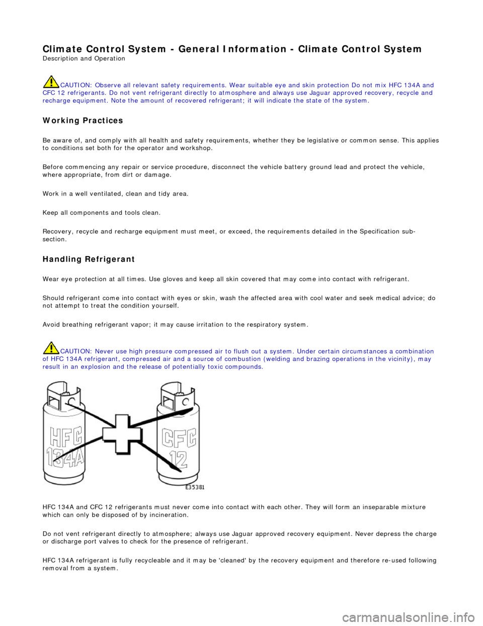
HFC 134A and CFC 12 refrigerants must neve r come into contact with each other. They will form an inseparable mixture
which can only be disposed of by incineration.
Do not vent refrigerant directly to atmo sphere; always use Jaguar approved recove ry equipment. Never depress the charge
or discharge port valves to check for the pr esence of refrigerant.
HFC 134A refrigerant is fully recycleable and it may be 'cleaned' by the recovery equipment and therefore re-used following
removal from a system.
Page 1754 of 2490

WARNING: NEVER USE A CFC 12 ANALYZ
ER OR NAKED FLAME TYPE.
Leak tests should be carried out with a UV spot lamp or an electronic analyzer which is dedicated to HFC 134A refrigerant.
Handling Lubricati
ng Oil
Av
oid breathing lubricant mist; it can cau
s
e irritation to the respiratory system.
Always use fresh oil from a sealed containe r and do not leave oil exposed to the atmosphere for any reason other than to fill
or empty a system. PAG oil is very hygr oscopic (absorbs water) and will rapidly become contaminated by atmospheric
moisture.
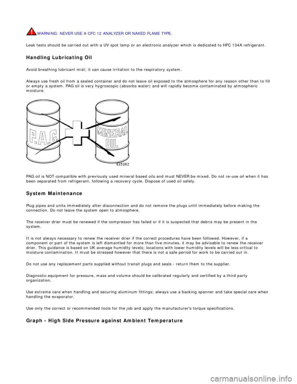
PAG oil is NOT compatible with previously used mineral based oi ls and must NEVER be mixed. Do not re-use oil when it has
been separated from refrigerant, following a re covery cycle. Dispose of used oil safely.
System Maintenance
Plug pipes an
d units immediatel
y after disconnection an d do not remove the plugs until immediately before making the
connection. Do not leave the system open to atmosphere.
The receiver drier must be renewed if the compressor has failed or if it is susp ected that debris may be present in the
system.
It is not always necessary to renew th e receiver drier if the correct procedur es have been followed. However, if a
component or part of the system is left dismantled for more than five minutes, it may be advisable to renew the receiver
drier. This guidance is based on UK average humidity levels; lo cations with lower humidity levels will be less critical to
moisture contamination. It must be stressed however th at there is not a safe period for work to be carried out in.
Do not use any replacement parts su pplied without transit plugs and seals - return them to the supplier.
Diagnostic equipment for pres sure, mass and volume should be calibrated regularly and certified by a third party
organization.
Use extreme care when handling and securi ng aluminum fittings; always use a backing spanner and take special care when
handling the evaporator.
Use only the correct or re commended tools for the job and apply the manufacturer's torque specifications.
Graph - High S
ide Pressure against Ambient Temperature