1998 JAGUAR X308 ESP
[x] Cancel search: ESPPage 1823 of 2490
8.8. Automatic
Symbol indicates when the control of , temperature, fan speed and air distribution are all in Auto mode.
9. 9. External
There are two modes of external ambient temperature selection;
Quick Display. Pressing the button for <1.5 seconds (con firmed by a single bleep) will display the external
temperature for 4 seconds.
Continuous Display. Pressing and holding the button fo r >1.5 seconds (confirmed by two beeps) displays the
external ambient temperature continuously, the value of which will be updated every 4 seconds given that vehicle
road speed is > 25 km/h. Pressing the button again fo r <1.5 seconds resets to the previous display.
• NOTE: Continuous external temperature display will be cancel led when the ignition is switched OFF but not during engine
cranking.
10. 10. A/C
This push-on / push-off button will either select or deselect (as indicated by the state lamp) the refrigeration system.
The refrigeration system is automatically engaged when the Auto button is pressed.
• NOTE: Interior misting of screens may be reduced by continuous operation of th e refrigeration system.
11. 11. Auto
When selected and the state lamp lit, A/C mode will be operat ional and control of vent outlet temperature, fans speed and
air distribution will be automatic.
AUTO mode will disengage should manual air distribution or defrost buttons be operated or the manual fan speed knob be
rotated.
• NOTE: Automatic temperature control is constantly main tained irrespective of selected manual overrides.
12. 12. Defrost
Push-on push-off button, which when engaged will direct all air to the front and side glass at maximum fan speed. The
heated windshield (if fitted) will also be energized for a timed cycle of 6,5 minute s, but may be cancelled by pressing the
HEATED WINDSHIELD (F) button. Pressing 'DEF' again will retu rn to the last setting with automatic temperature control
being maintained.
Directing warm and humid air onto a cold screen can produce interior misting of screens. Operating the climate control
system without the refrigerati on system operating will exacerbate this problem.
• NOTE: Directing cold air onto the screen in warm humid conditions can produce external condensation.
13. 13. Heated Windshield (F)
Pressing the heated windshield button (whe re fitted) will energize the electrically heated windshield elements for a timed
cycle of 6,5 minutes; pressing the button again will cancel the request. Should the engine stall or the ignition be turned
OFF, the timer will be cleare d and the function cancelled.
• NOTE: The heated windshield may be activated with the cl imate control system OFF but the engine must be running.
In very cold ambient temperatures, icing of the interior of the glass is possible when the climate control system is operating
in AUTO mode; to reduce this poss ibility the A/CCM provides automatic operation of the heated windshield.
With the following conditions met, the heated windshield will automatically energize but the state lamp will NOT be lit.
Page 1830 of 2490
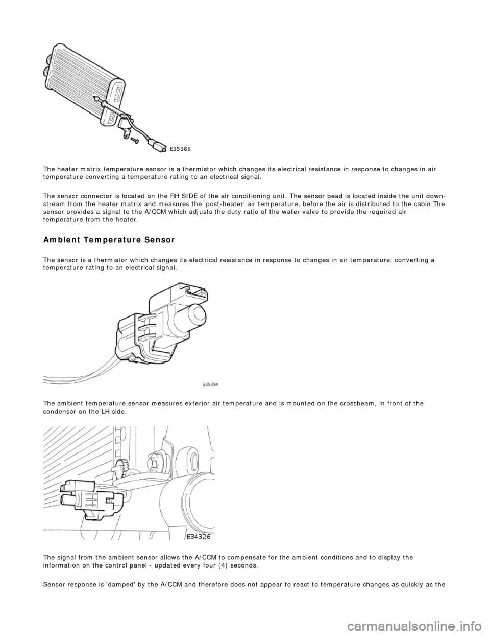
The heater matrix temperature sensor is a thermistor which changes its electrical resistance in response to changes in air
temperature converting a temperature rating to an electrical signal.
The sensor connector is located on the RH SIDE of the air conditioning unit. The sensor bead is located inside the unit down-
stream from the heater matrix and measures the 'post-heater' air temperature, before the air is distribu ted to the cabin The
sensor provides a signal to the A/CCM which adjusts the duty ratio of the water valve to provide the required air
temperature from the heater.
Ambient Temperature Sensor
The sensor is a thermistor which changes its electrical resistance in response to changes in air temperature, converting a
temperature rating to an electrical signal.
The ambient temperature sensor measures exterior air temper ature and is mounted on the crossbeam, in front of the
condenser on the LH side.
The signal from the ambient sensor allo ws the A/CCM to compensate for the ambient conditions and to display the
information on the control panel - updated every four (4) seconds.
Sensor response is 'damped' by the A/CCM and ther efore does not appear to react to temperature chan
ges as quickly as the
Page 1831 of 2490
other sensors. This feature prevents the effects of sudden changes in air outlet temperatures due to factors such as:
Recirculating air from the engine cooling pack at low vehicle speeds Sudden changes in ambient temperature The effects of water splash
Motorised In-car Aspirator.
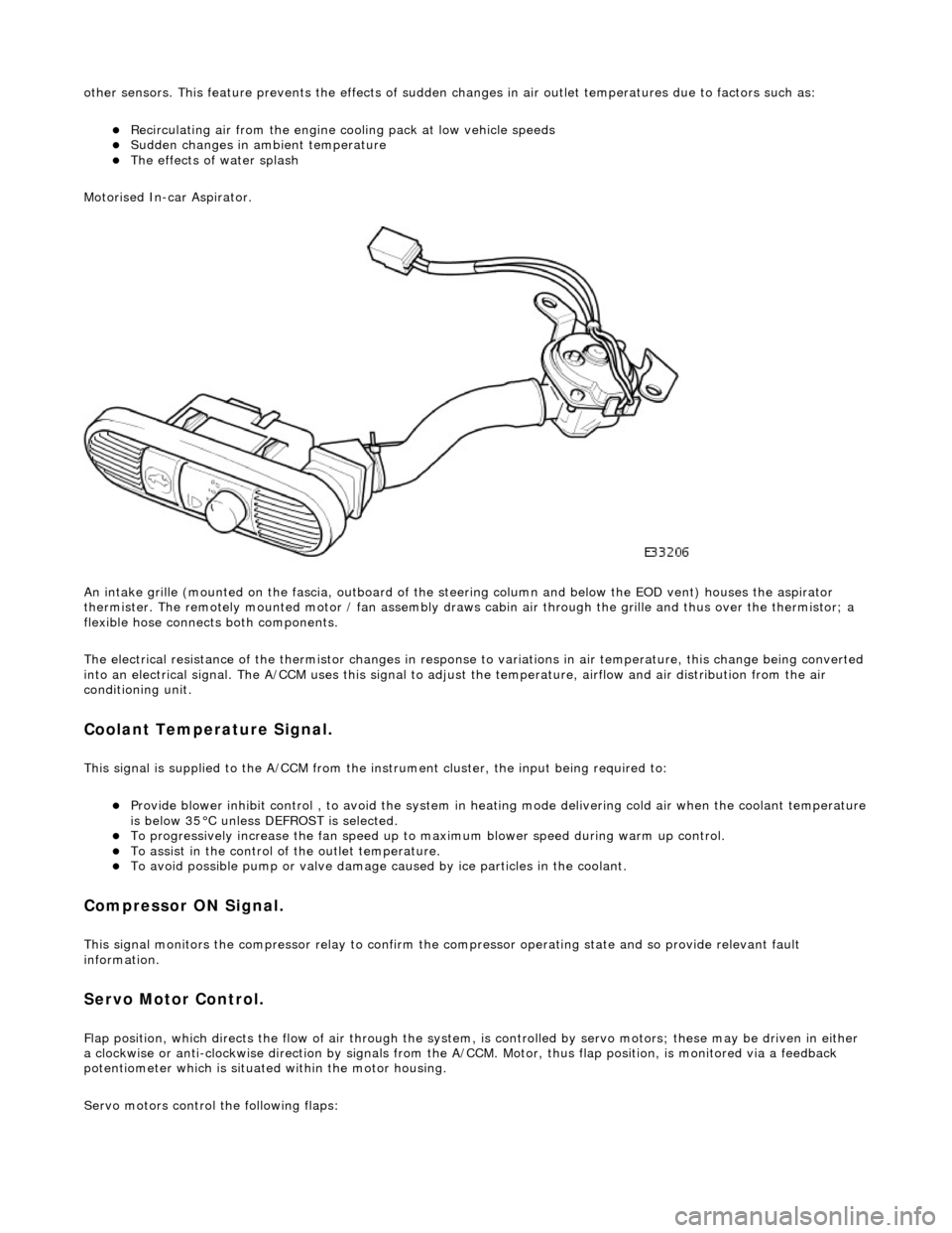
An intake grille (mounted on the fascia , outboard of the steering column and below the EOD vent) houses the aspirator
thermister. The remotely mounted motor / fan assembly draws ca bin air through the grille and thus over the thermistor; a
flexible hose connects both components.
The electrical resistance of the thermistor changes in response to variations in air temperatur e, this change being converted
into an electrical signal. The A/CCM uses this signal to adjust the temperature, airflow and air distribution from the air
conditioning unit.
Coolant Temperature Signal.
This signal is supplied to the A/CCM from the instrument cluster, the input being required to:
Provide blower inhibit control , to avoid the system in heat ing mode delivering cold air when the coolant temperature is below 35°C unless DEFROST is selected. To progressively increase the fan speed up to maximum blower speed during warm up control. To assist in the control of the outlet temperature. To avoid possible pump or valve damage ca used by ice particles in the coolant.
Compressor ON Signal.
This signal monitors the compressor relay to confirm the compressor operating state and so provide relevant fault
information.
Servo Motor Control.
Flap position, which directs the flow of air through the system, is controlled by servo motors; these may be driven in either
a clockwise or anti-clockwise direction by signals from the A/ CCM. Motor, thus flap position, is monitored via a feedback
potentiometer which is situated within the motor housing.
Servo motors control the following flaps:
Page 1859 of 2490
Horn - Horn
Description and Operation
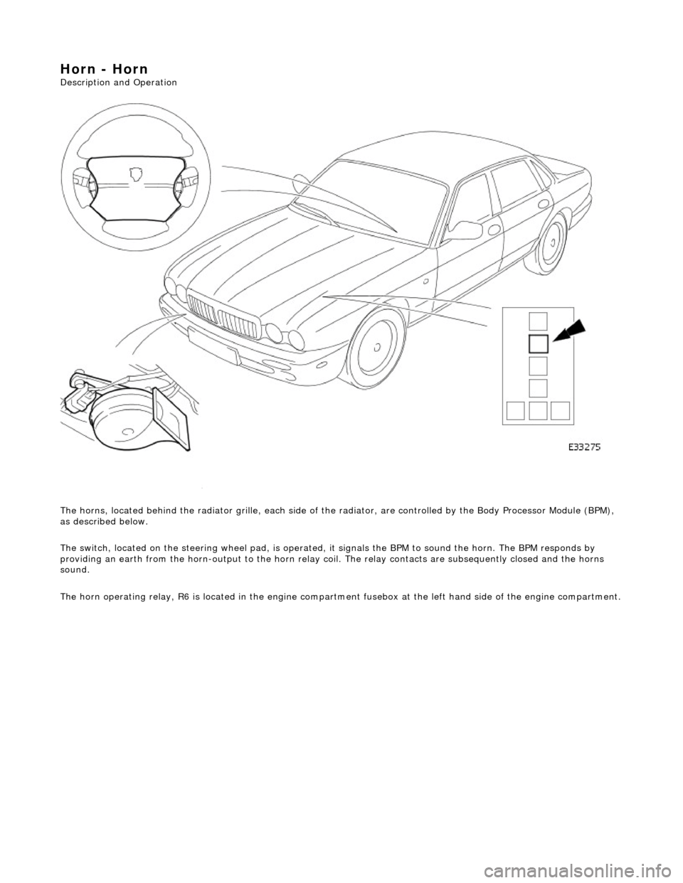
The horns, located behind the radiator gril le, each side of the radiator, are controlled by the Body Processor Module (BPM),
as described below.
The switch, located on the steering wheel pad, is operated, it signals the BPM to sound the horn. The BPM responds by
providing an earth from the horn-output to the horn relay coil. The relay contacts are subsequently closed and the horns
sound.
The horn operating relay, R6 is located in the engine compartm ent fusebox at the left hand side of the engine compartment.
Page 1919 of 2490
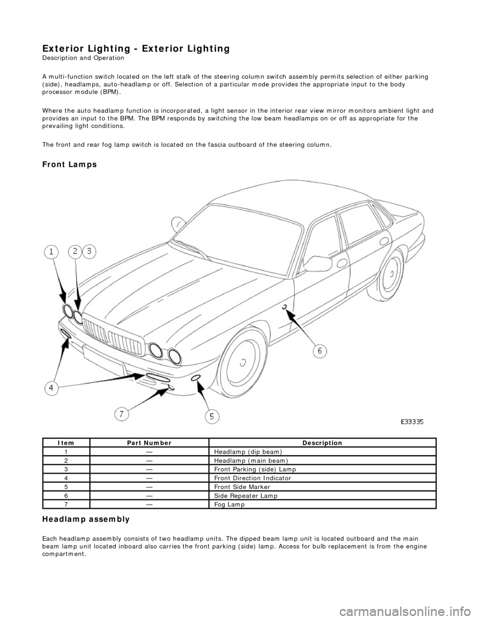
Exterior Lighting - Exterior Lighting
Description and Operation
A multi-function switch located on the left stalk of the steering column switch assembly permits selection of either parking
(side), headlamps, auto-headlamp or off. Selection of a particular mode provides the appropriate input to the body
processor module (BPM).
Where the auto headlamp function is incorporated, a light sensor in the interior rear view mirror monitors ambient light and
provides an input to the BPM. The BPM responds by switching the low beam headlamps on or off as appropriate for the
prevailing light conditions.
The front and rear fog lamp switch is located on the fascia outboard of the steering column.
Front Lamps
Headlamp assembly
Each headlamp assembly consists of tw o headlamp units. The dipped beam lamp unit is located outboard and the main
beam lamp unit located inboard also carries the front parking (side) lamp. Access for bulb replacement is from the engine
compartment.
ItemPart NumberDescription
1—Headlamp (dip beam)
2—Headlamp (main beam)
3—Front Parking (side) Lamp
4—Front Direction Indicator
5—Front Side Marker
6—Side Repeater Lamp
7—Fog Lamp
Page 1920 of 2490
Direction indicator and side marker lamps
Each front direction indicator and side marker lamp is retained in the bumper cover by a lug at one end and a spring clip at
the other end. The side marker lamps are not electrically connected for certain markets.
The side repeater lamps are secured by sp ring clips on the lower edge of the lamp unit. In certain markets Jaguar leaper
badges are substituted for side repeater lamps.
Fog lamps
The fog lamps are located in recesses in the front bump er and secured by three screws. The la mps which are not
interchangeable left to right, are accessed from the rear of the bumper.
Operation
All lamps are controlled by the BPM which provides an appropriate output in response to an input received when a selected
switch is operated.
All lamps receive an input direct from th e BPM with the exception of the main be am, dip beam and front fog lamps which
receive an input from the BPM vi a the respective relays and fuses; refer to section 418-01.
Fault analysis must be undertaken using the PDU. Refer to Diagnosis and Testing.
Consult the relevant Electrical Guid e for details of circuit operation.
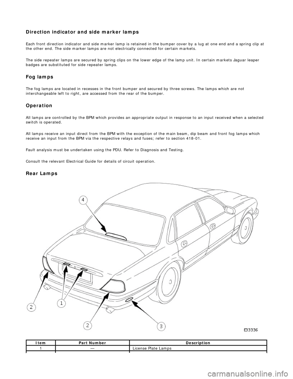
Rear Lamps
ItemPart NumberDescription
1—License Plate Lamps
Page 1921 of 2490
License plate lamps
Each license plate bulb is accessible after removing the relevant lens. The license plate lamps can be accessed following
removal of the trunk lid liner and upper trim finisher.
Rear lamp assembly
Each rear lamp assembly incorporates a stop/tail lamp, a fog lamp, a reversing lamp and a direction indicator lamp. Access
for bulb replacement is from the trunk.
Side markers
Each side marker is retained in the bumper cover by a lug on one end of the unit and a spring clip at the other end. The unit is not electrically connected for all markets.
High mounted stop lamp
The high mounted stop lamp (HMSL) is secu red to studs on the center lower edge of the backlight and provides illumination
using five bulbs.
Operation
All lamps are controlled by the BPM which pr ovides an appropriate output in response to an input received when a selected
switch is operated.
The side marker lamps receive an input from the BPM via relay 3 and fuse F21. The license plate lamps receive an input
from the BPM via relay 3 and fuse F19. The rela y and fuses are located in the trunk fuse-box.
The tail lamps receive an input direct from the BPM.
The stop, reversing and rear fog lamps are controlled by the security and locking module (SLM) which receives inputs via
the SCP network from the BPM.
The HMSL is not controlled by the SLM; it receives input from the brake switch via relay 5 and fuse F8 in the trunk fuse-box.
The BPM and SLM monitor the stop lamps (n ot HMSL) and tail lamps for failure.
Fault analysis must be undertaken using the PDU, refer to Diagnosis and Testing.
Consult the relevant Electrical Guid e for details of circuit operation.
2—Rear Lamp Assembly
3—Rear Side Marker
4—High Mounted Stop Lamp
Page 1962 of 2490
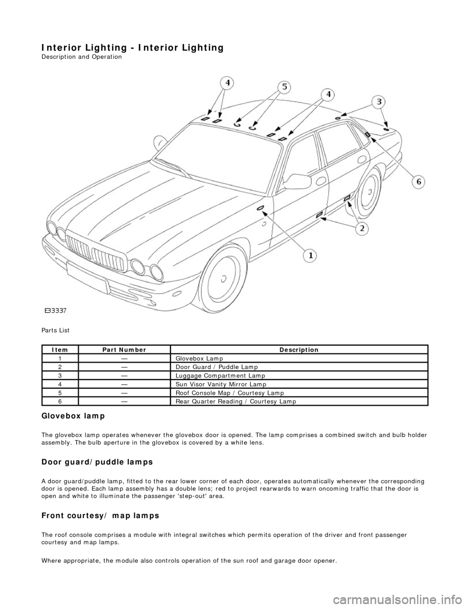
Interior Lighting - Interior Lighting
Description and Operation
Parts List
Glovebox lamp
The glovebox lamp operates whenever the glovebox door is opened. The lamp comprises a combined switch and bulb holder assembly. The bulb aperture in the glovebox is covered by a white lens.
Door guard/puddle lamps
A door guard/puddle lamp, fitted to the rear lower corner of each door, operates automatically whenever the corresponding
door is opened. Each lamp assembly has a double lens; red to project rearwards to warn oncoming traffic that the door is
open and white to illuminate the passenger 'step-out' area.
Front courtesy/ map lamps
The roof console comprises a module with integral switches which permits operation of the dr iver and front passenger
courtesy and map lamps.
Where appropriate, the module also controls operation of the su n roof and garage door opener.
ItemPart NumberDescription
1—Glovebox Lamp
2—Door Guard / Puddle Lamp
3—Luggage Compartment Lamp
4—Sun Visor Vanity Mirror Lamp
5—Roof Console Map / Courtesy Lamp
6—Rear Quarter Reading / Courtesy Lamp