1998 JAGUAR X308 ESP
[x] Cancel search: ESPPage 1972 of 2490
Daytime Running Lamps (DRL) - Daytime Running Lamps (DRL)
Diagnosis and Testing
Tests Using the Portable Diagnostic Unit
Refer to PDU User Guide
The complexity of the electronics involved with the Body Pr ocessor and the multiplexed communication networks which are
associated with it, preclude the use of wo rkshop general electrical test equipment. Therefore, reference should be made to
the PDU User Guide for detail ed instructions on testing the Daytime Running Function.
The Daytime Running function is exactly the same as for the normal operation of the side lamps (or dipped beam, where
specified) in as much as the body processor drives the same lamps from the same outputs.
The body processor has been programmed to respond to an alternative set of cond itions in order to operate the lamps,
instead of waiting for a signal from the normal light switch.
The conditions which have to be set are; ignition switch se t to position II or III and sidelight switch set to OFF. The
sidelights, side marker lamps (if fitted and enabled), tail lights and number plate lights will all be switched ON.
The PDU systematically tests and analyses all functions of the daytime running lamps.
Where a fault is indicated, before replac ing a component, some basic diagnostic methods may be necessary to confirm that
connections are good and that wiring is not damaged.
Page 1989 of 2490

Wiring Harnesses - Wiring Harness
Description and Operation
Introduction
CAUTION: Do not use any other heat shrink sleeve other than the approved glue lined heat shrink sleeve mentioned
in the repair procedure.
The purpose of this document is to promote quick and efficient minor repair to harness connectors or cables using approved
methods and the wiring harness repair kit. Repairs may only be made to cables and connectors which have been
mechanically, not electrically damaged. It also applies wher e the whole extent of the damage can be clearly identified and
rectified.
Care and neatness are essential requir ements in making a perfect repair.
Caution:
At the time of this first issue of the Harness Repair Guide, do not approve re pairs to any of the following circuits:
Any media orientated system transport network harnesses. Supplement restraint system (SRS) firing circuits (Air bags). Link lead assembles, which are unique to safety critical circuits such as anti-lock brake system (ABS) and
thermocouple circuits. An example of this is the ABS wheel speed sensors with moulded connectors.
4. Screened cables, leads and wiring harness(s).
If any harness(s) with defective electrical connector te rminals or wires from the above circuits are a concern,
new components must be installed.
Repair Kit
CAUTION: Where the repair procedure indica tes that a glue lined heat shrink sleeve should be applied, apply sufficient
heat to the glue lined heat shrink to melt the glue in order to provide a water tight seal. Do not over heat the glue lined
heat shrink sleeve so that the wiring harness insulation becomes damaged.
The wiring harness repair kit has been produced which comprises:
Pre-terminated wiring harness(s) of different sizes and types Three sizes of butt splice connectors A selection of colored cable identification sleeves Two sizes of glue lined heat shrink sleeves Crimping pliers A wire cutter and insulation stripper An electrical connector terminal extraction handle and tips
A suitable heat source, fo r shrinking heat shrink sleeves will be required.
The pre-insulated diamond grip range of el ectrical connector terminals and in-line, butt splice connectors contained within
the wiring harness repair kit are the only acceptable product for the repairs of wi ring harnesses. The butt connectors not
only grip the wire but also the insu lation, making a very secure joint.
If an electrical connector terminal is not included in the wiring harness repair kit then approval for the repair is NOT given
and in these circumstances a new wi ring harness must be installed.
Pre-Terminated Wiring Harness( s) and Butt Splice Connectors
All pre-terminated wiring harness(s) and butt splice connectors in the wiring harness repair kit are contained in bags which
can be resealed after use. Each bag is marked with the part number of the items stored within the bag. Each storage
compartment in the wiring harness repair kit is identified with the corresponding part number. Make sure that pre-
terminated wiring harness(s) and connectors are not mixed up it is advisable to only open one bag at a time and to reseal
Page 1995 of 2490
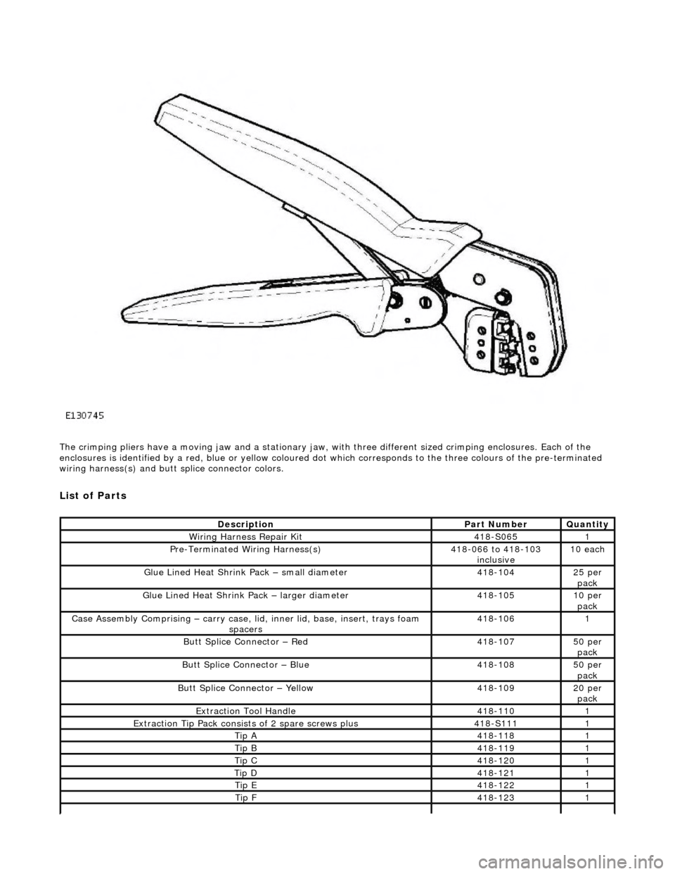
The crimping pliers have a moving jaw and a stationary jaw, with three different sized crimping enclosures. Each of the
enclosures is identified by a red, blue or yellow coloured dot which correspon ds to the three colours of the pre-terminated
wiring harness(s) and butt splice connector colors.
List of Parts
DescriptionPart NumberQuantity
Wiring Harness Repair Kit 418-S0651
Pre-Terminated Wiring Harness(s)418-066 to 418-103
inclusive 10 each
Glue Lined Heat Shrink Pack – small diameter418-10425 per
pack
Glue Lined Heat Shrink Pack – larger diameter418-10510 per pack
Case Assembly Comprising – carry case, li d, inner lid, base, insert, trays foam
spacers418-1061
Butt Splice Connector – Red 418-10750 per pack
Butt Splice Connector – Blue 418-10850 per
pack
Butt Splice Connector – Yellow 418-10920 per pack
Extraction Tool Handle 418-1101
Extraction Tip Pack consists of 2 spare screws plus 418-S1111
Tip A418-1181
Tip B418-1191
Tip C418-1201
Tip D418-1211
Tip E418-1221
Tip F418-1231
Page 2007 of 2490
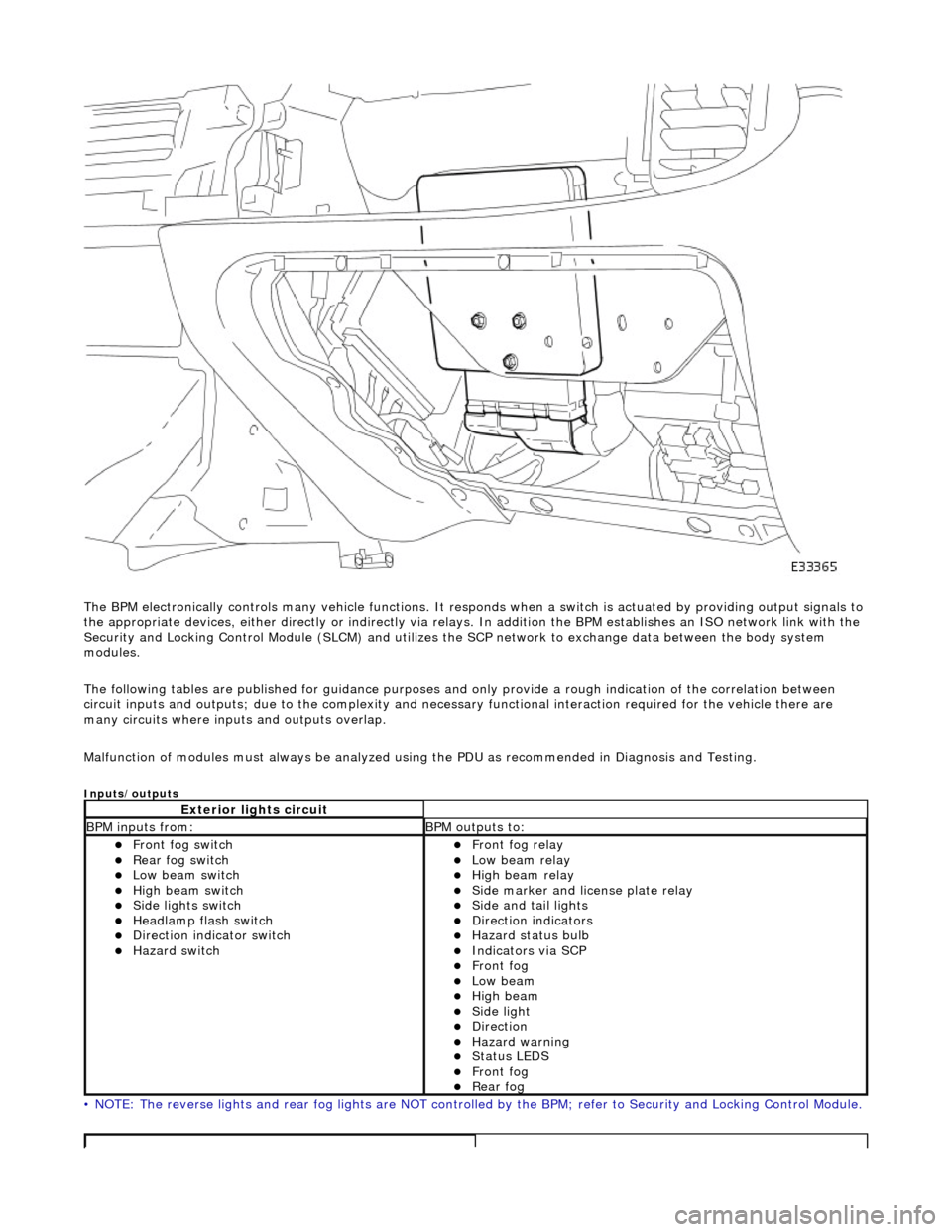
The BPM electronically controls many vehicle functions. It responds when a switch is actuated by providing output signals to
the appropriate devices, either di rectly or indirectly via relays. In addition the BPM establishes an ISO network link with the
Security and Locking Control Module (SLC M) and utilizes the SCP network to exchange data between the body system
modules.
The following tables are publis hed for guidance purposes and only provide a rough indication of the correlation between
circuit inputs and outputs; due to the complexity and necess ary functional interaction required for the vehicle there are
many circuits where inpu ts and outputs overlap.
Malfunction of modules must always be analyzed using the PDU as recommended in Diagnosis and Testing.
Inputs/outputs
• NOTE: The reverse lights and rear fog lights are NOT controlled by the BPM; refer to Security and Locking Control Module.
Exterior lights circuit
BPM inputs from: BPM outputs to:
Front fog switch Rear fog switch Low beam switch High beam switch Side lights switch Headlamp flash switch Direction indicator switch Hazard switch
Front fog relay Low beam relay High beam relay Side marker and license plate relay Side and tail lights Direction indicators Hazard status bulb Indicators via SCP Front fog Low beam High beam Side light Direction Hazard warning Status LEDS Front fog Rear fog
Page 2099 of 2490
Exterior Trim and Ornamentation - Exterior Trim
Description and Operation
Body Front
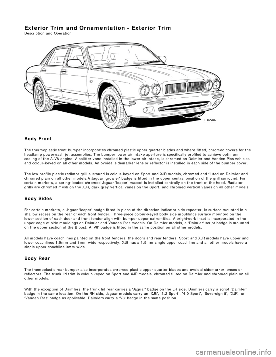
The thermoplastic front bumper incorporates chromed plastic upper quarter blades and where fitted, chromed covers for the headlamp powerwash jet assemblie s. The bumper lower air intake aperture is specifically profiled to achieve optimum
cooling of the AJV8 engine. A splitter vane installed in the lowe r air intake, is chromed on Daimler and Vanden Plas vehicles
and colour-keyed on all other models. An ov oidal sidemarker lens or reflector is installed in each side of the bumper cover.
The low profile plastic radiator grill surround is colour-keyed on Sport and XJR mo dels, chromed and fluted on Daimler and
chromed plain on all other models .A Jaguar 'growler' badge is fitted in the upper central positi on of the grill surround. For
certain markets, a spring-loaded chromed Ja guar 'leaper' mascot is installed centrally on the front of the hood. Radiator
grills are chromed mesh on the XJR, dark grey vertical vanes on the Sport, and chromed ve rtical vanes on all other models.
Body Sides
For certain markets, a Jaguar 'l eaper' badge fitted in place of the direction indicator side re peater, is surface mounted in a
shallow recess on the rear of each fro nt fender. Three-piece colour-keyed body side mouldings surface mounted on the
lower section of each door and front fender align with bumper upper extremities. A brightwork inset is incorporated in the
upper edge of side mouldings on Daimler and Vanden Plas models. On Daimler models, a 'Daimler' script badge is mounted
on the upper section of the B post. A 'V8' badge is fitted in the same position on all other models.
All models have coachlines painted on th e front fenders, the doors and rear fender s. Sport and XJR models have upper and
lower coachlines 1.5mm an d 3mm wide respectively, XJ8 has a 1.5mm single upper coachline and all other models have a
single upper coachline 3mm wide.
Body Rear
The themoplastic rear bumper also inco rporates chromed plastic upper quarter blades and ovoi dal sidemarker lenses or
reflectors. The trunk lid trim is colour-keyed on Sport and XJ R models, chromed fluted on Daimler and chromed plain on all
other models.
With the exception of Daimlers, the trunk lid rear carries a 'Jaguar' badge on the LH side. Daimlers carry a script 'Daimler'
badge in the same location. On th e RH side, Jaguar models carry an 'XJ8', '3.2 Sport', '4.0 Sport', 'Sovereign 8', 'XJR', or
'Vanden Plas' badge as applic able. Daimlers carry a 'V8' badge in the same position.
Page 2273 of 2490
Handles, Locks, Latches and Entry Systems - Handles, Locks, Latches and
Entry Systems
Description and Operation
Door Lock Mechanism
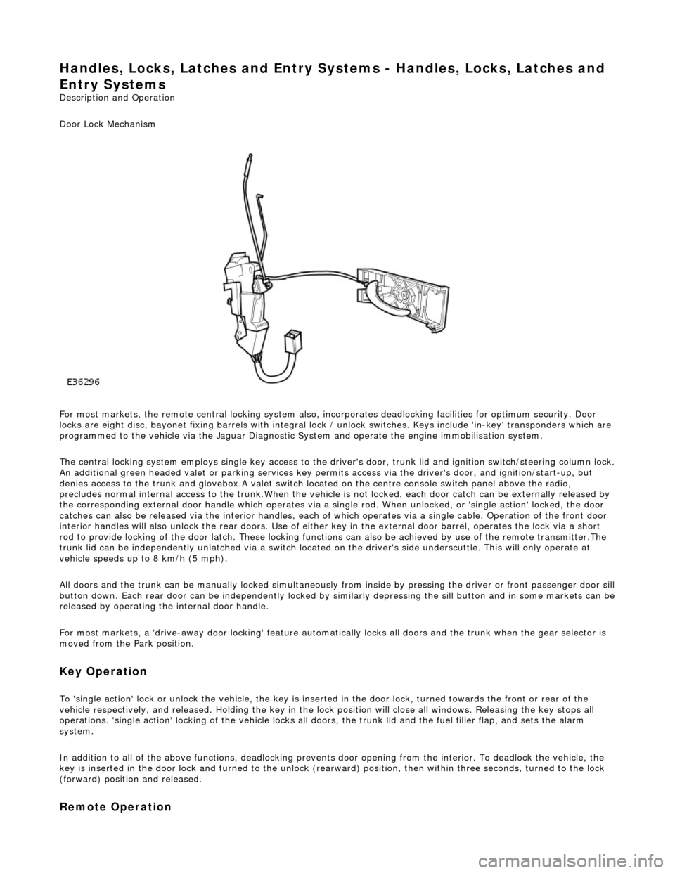
For most markets, the remote central locking system also, in corporates deadlocking facilities for optimum security. Door
locks are eight disc, bayonet fixing barrels with integral lock / unlock switches. Keys include 'in-key' transponders which are
programmed to the vehicle via the Jaguar Diagnostic Sy stem and operate the engine immobilisation system.
The central locking system employs single key access to the driv er's door, trunk lid and ignition switch/steering column lock.
An additional green headed valet or park ing services key permits access via the driver's door, and ignition/start-up, but
denies access to the trunk and glovebox.A valet switch located on the centre console switch panel above the radio,
precludes normal internal access to the trunk.When the vehicle is not locked, each door catch can be externally released by
the corresponding external door handle which operates via a si ngle rod. When unlocked, or 'single action' locked, the door
catches can also be released via the interior handles, each of which operates via a single cable. Operation of the front door
interior handles will also unlock the rear doors. Use of either key in the external door barrel, operates the lock via a short
rod to provide locking of the door latch. These locking functions can also be achieved by use of the remote transmitter.The
trunk lid can be independently unlatched via a switch located on the driver's side underscuttle. This will only operate at
vehicle speeds up to 8 km/h (5 mph).
All doors and the trunk can be manually lock ed simultaneously from inside by pressing the driver or front passenger door sill
button down. Each rear door can be independently locked by si milarly depressing the sill button and in some markets can be released by operating the internal door handle.
For most markets, a 'drive-away door locking' feature automati cally locks all doors and the trunk when the gear selector is
moved from the Park position.
Key Operation
To 'single action' lock or unlock the vehicle, the key is inserted in the door lock , turned towards the front or rear of the
vehicle respectively, and released. Holding the key in the lock position will close all windows. Releasing the key stops all
operations. 'single action' locking of the vehicle locks all doors, the trunk lid and the fuel filler flap, and sets the alarm
system.
In addition to all of the above functions, deadlocking prevents door opening from th e interior. To deadlock the vehicle, the
key is inserted in the door lock and turned to the unlock (rearw ard) position, then within three seconds, turned to the lock
(forward) position and released.
Remote Operation
Page 2307 of 2490
cooling duct.
The windshield washer is operated by pressing the button at the end of the wiper control stalk switch. Pressing and
releasing the button operates the washer for 1 to 1.4 seconds and the wiper completes three sweeps. An optional drip wipe
function adds a further sweep of the wiper after a 4 second delay, to clear residual fluid from the windshield. If the button is
held depressed, the washer and wiper will operate continuous ly for up to 20 seconds. When the button is released, the
wiper will again complete three further sweeps.
Headlamp Powerwash
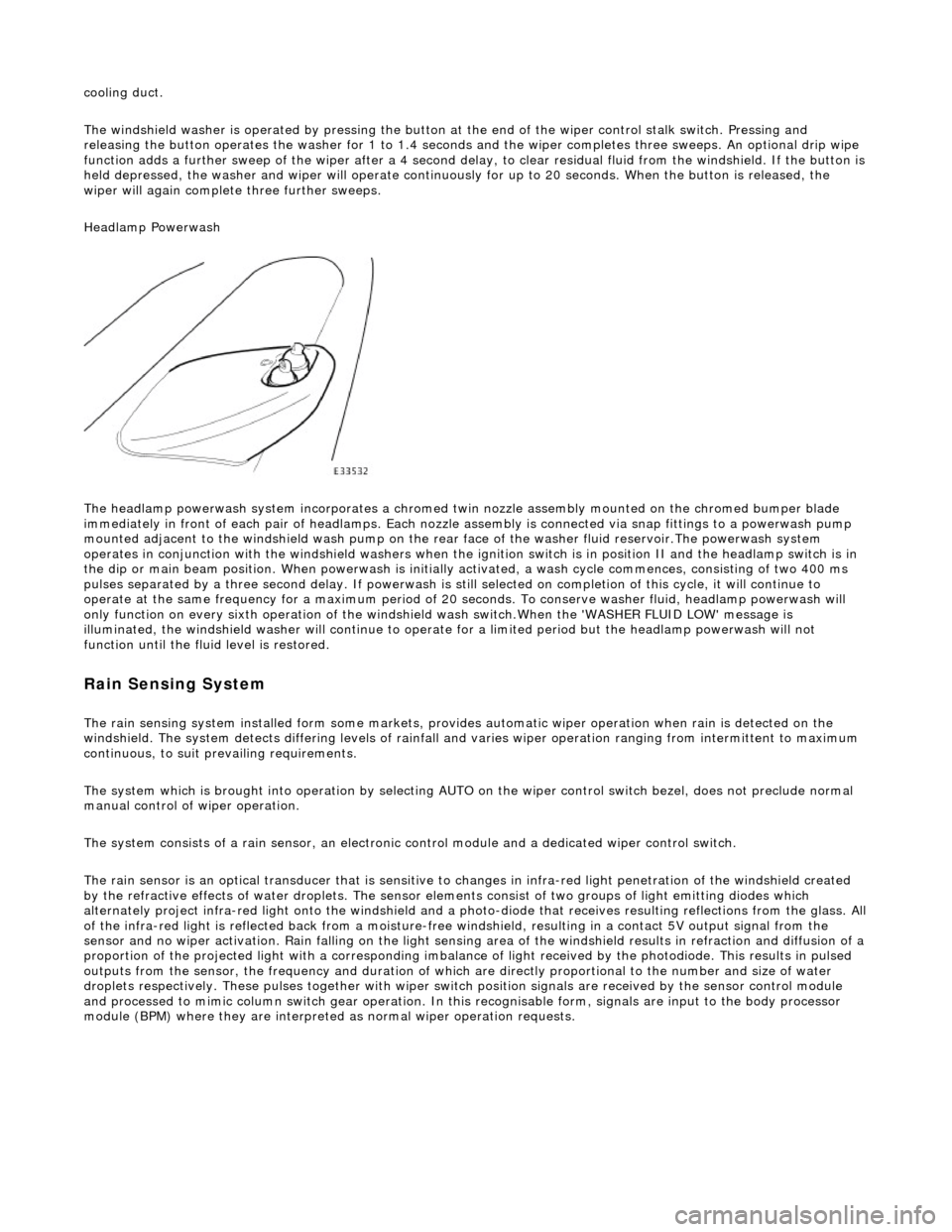
The headlamp powerwash system incorporates a chromed twin nozzle assembly mounted on the chromed bumper blade
immediately in front of each pair of he adlamps. Each nozzle assembly is connected via snap fittings to a powerwash pump
mounted adjacent to the windshield wash pump on the rear face of the washer fluid reservoir.The powerwash system
operates in conjunction with the windshield washers when the ignition switch is in position II and the headlamp switch is in
the dip or main beam position. When powerwash is initially activated, a wash cycle commences, consisting of two 400 ms
pulses separated by a three second delay. If powerwash is still selected on completion of this cycle, it will continue to
operate at the same frequency for a maximum period of 20 se conds. To conserve washer fluid, headlamp powerwash will
only function on every sixth operation of the windshie ld wash switch.When the 'WASHER FLUID LOW' message is
illuminated, the windshield washer will continue to operat e for a limited period but the headlamp powerwash will not
function until the fluid level is restored.
Rain Sensing System
The rain sensing system installed form so me markets, provides automatic wiper operation when rain is detected on the
windshield. The system detects differing le vels of rainfall and varies wiper operation ranging from intermittent to maximum
continuous, to suit prevailing requirements.
The system which is brought into operation by selecting AUTO on the wiper control switch bezel, does not preclude normal
manual control of wiper operation.
The system consists of a rain sensor, an electronic control module and a dedicated wiper control switch.
The rain sensor is an optical transducer that is sensitive to changes in infra-red light penetration of the windshield created
by the refractive effects of water drople ts. The sensor elements consist of two groups of light emitting diodes which
alternately project infra-red light onto th e windshield and a photo-diode that receiv es resulting reflections from the glass. A ll
of the infra-red light is reflected back from a moisture-free windshield, resulting in a contact 5V output signal from the
sensor and no wiper activation. Rain falling on the light sensing area of the wi ndshield results in refraction and diffusion of a
proportion of the projected light with a corresponding imbalance of light received by the photodiode. This results in pulsed
outputs from the sensor, the frequency and duration of which are directly proportional to the number and size of water
droplets respectively. These pulses together with wiper switch position signals are received by the sensor control module
and processed to mimic column switch gear operation. In this recognisable form, signals are input to the body processor
module (BPM) where they are interprete d as normal wiper operation requests.
Page 2370 of 2490
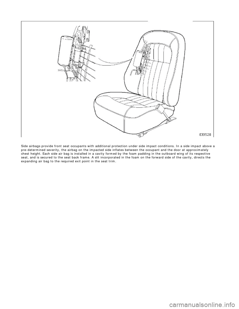
Side airbags provide front seat occupants with additional protection under side impa ct conditions. In a side impact above a
pre-determined severity, the ai rbag on the impacted side inflates between the occupant an d the door at approximately
chest height. Each side air bag is installe d in a cavity formed by the foam padding in the outboard wing of its respective
seat, and is secured to the seat back frame . A slit incorporated in the foam on the forward side of the cavity, directs the
expanding air bag to the required exit point in the seat trim.