Page 2326 of 2490
8. Conne
ct key interlock solenoid harness multiplug.
9. Connect key t
ransponder exciter
coil multiplug and using new
tie straps, secure mu ltiplug to harness.
10 . Conne
ct wiper/washer switch mu
ltiplug, and fit multiplug onto
retaining bracket.
11. Fit driver side underscu ttle. Refer to 76.46.11.
12. Fit steering column uppe r cowl. Refer to 76.46.02.
13. Fit steering column lower cowl. Refer to 76.46.03
14. Fit steering wheel.
15. Fit driver airbag module. Refer to 76.73.39.
16. Fit groun
d cable to battery te
rminal and fit battery cover.
Refer to 86.15.15.
Page 2329 of 2490
Roof Opening Panel - Motor Synchronization
General Procedures
1.
Remove sliding roof trim panel for access. Refer to 76.82.19.
2. Remove battery cover and disc onnect ground cable from
battery terminal. Refer to 86.15.19.
3. Remove roof console for ac cess. Refer to 76.13.69.90.
4. Remove sliding roof panel cont rol module. Refer to 86.76.07.
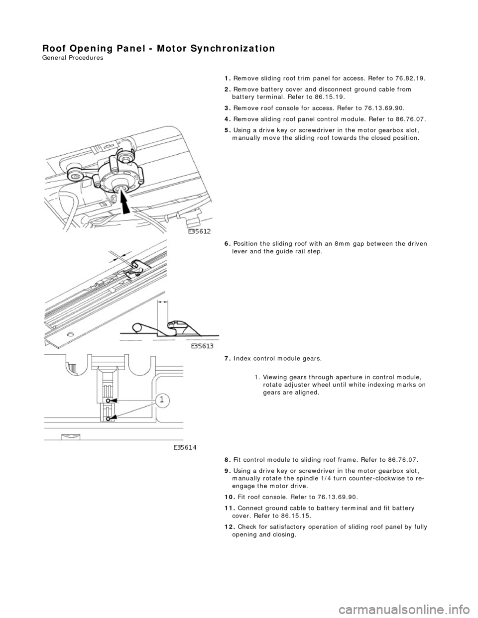
5. Using a drive key or screwdriver in the motor gearbox slot,
manually move the sliding roof towards the closed position.
6. Position the sliding roof with an 8mm gap between the driven
lever and the guide rail step.
7. Index control module gears.
1. Viewing gears through aperture in control module, rotate adjuster wheel until white indexing marks on
gears are aligned.
8. Fit control module to sliding r oof frame. Refer to 86.76.07.
9. Using a drive key or screwdriver in the motor gearbox slot,
manually rotate the spindle 1/4 turn counter-clockwise to re-
engage the motor drive.
10. Fit roof console. Refer to 76.13.69.90.
11. Connect ground cable to batt ery terminal and fit battery
cover. Refer to 86.15.15.
12. Check for satisfactory operation of sliding roof panel by fully
opening and closing.
Page 2344 of 2490
Bumpers - Front Bumper
Removal and Installation
Removal
WARNING: ENSURE THAT ALL PERSONNEL AND EQUIPMENT ARE CLEAR OF AREA BEFORE OPERATING RAMP.
1. Position vehicle on 4-post ramp.
2. Remove battery cover and disc onnect ground cable from
battery terminal. Refer to 86.15.19
3. Remove radiator surround and grill. Refer to 76.55.15 and
76.55.03.
4. Raise ramp to working height.
5. Using wheel-free lifts, remove front wheels.
6. Remove wheelarch liners for access.
7. Remove undertray. Refer to 76.22.90.
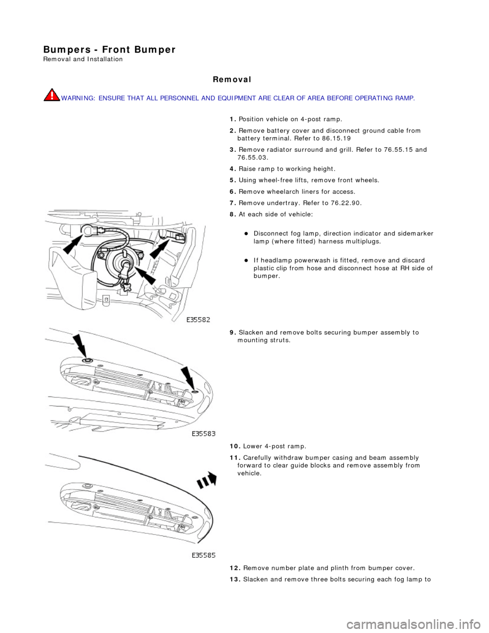
8. At each side of vehicle:
Disconnect fog lamp, directio n indicator and sidemarker
lamp (where fitted) harness multiplugs.
If headlamp powerwash is fitted, remove and discard
plastic clip from hose and disconnect hose at RH side of
bumper.
9. Slacken and remove bolts securing bumper assembly to
mounting struts.
10. Lower 4-post ramp.
11. Carefully withdraw bumper casing and beam assembly
forward to clear guide blocks and remove assembly from
vehicle.
12. Remove number plate and plinth from bumper cover.
13. Slacken and remove three bolts securing each fog lamp to
Page 2347 of 2490
Bumpers - Front Bumper and Bumper Cover
Removal and Installation
Removal
WARNING: ENSURE THAT ALL PERSONNEL AND EQUIPMENT ARE CLEAR OF AREA BEFORE OPERATING RAMP.
Installation
1. Position vehicle on 4-post ramp.
2. Remove battery cover and disc onnect ground cable from
battery terminal. Refer to 86.15.19.
3. Remove radiator surround and grill. Refer to 76.55.15 and
76.55.03.
4. Raise ramp to working height.
5. Using wheel-free lifts, remove front wheels.
6. Remove wheelarch liners for access.
7. Remove undertray. Refer to 76.22.90.
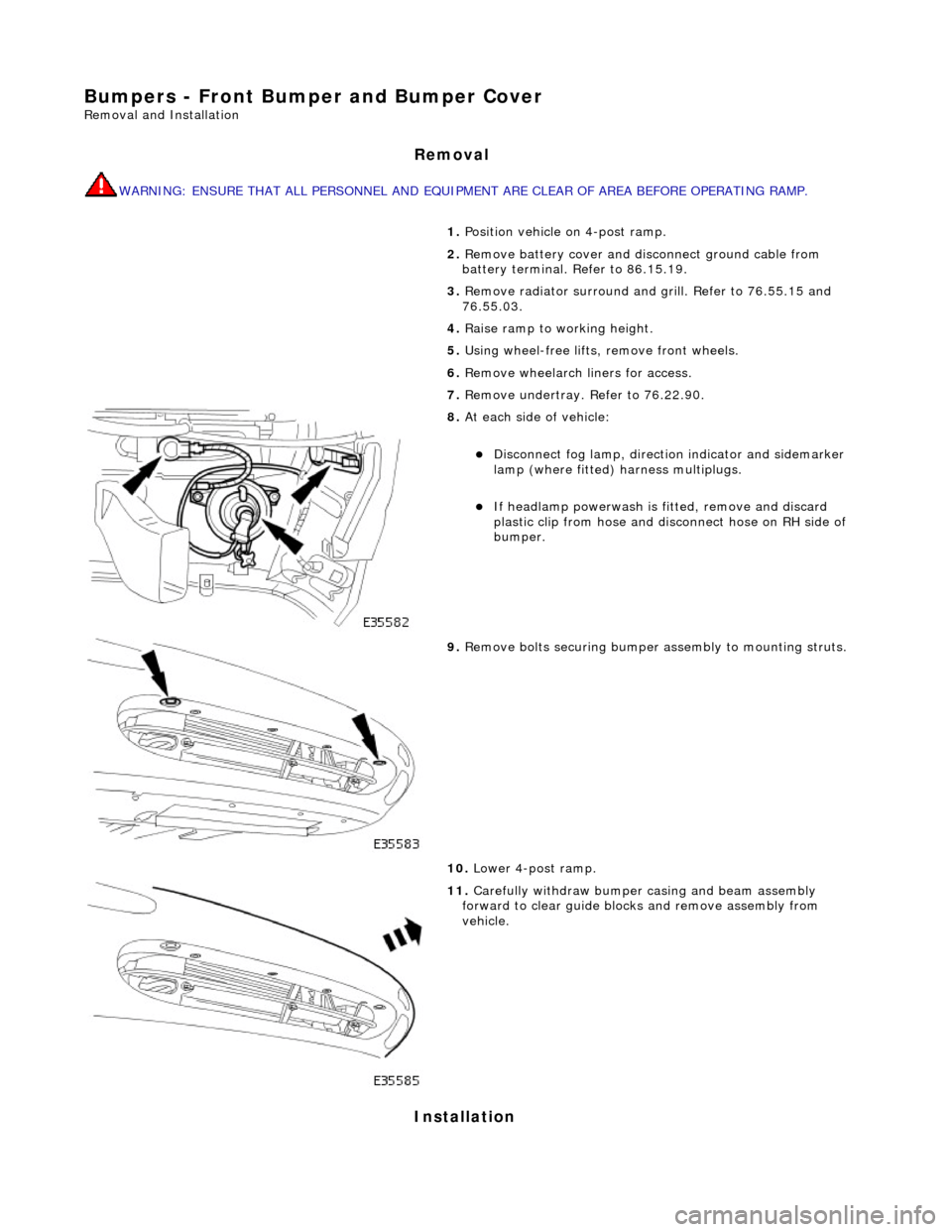
8. At each side of vehicle:
Disconnect fog lamp, directio n indicator and sidemarker
lamp (where fitted) harness multiplugs.
If headlamp powerwash is fitted, remove and discard
plastic clip from hose and disconnect hose on RH side of
bumper.
9. Remove bolts securing bumper assembly to mounting struts.
10. Lower 4-post ramp.
11. Carefully withdraw bumper casing and beam assembly
forward to clear guide blocks and remove assembly from
vehicle.
Page 2348 of 2490
1.
WARNING: ENSURE THAT ALL PERSONNEL AND
EQUIPMENT ARE CLEAR OF AREA BEFORE OPERATING RAMP.
Carefully slide bumper assembly onto fender guide blocks.
2. Raise ramp to working height.
3. Install but do not fully tighten bo lts securing bumper to struts.
4. Check clearance between top of bumper and bottom of fender.
If necessary, remove bumper, adjust guide blocks to achieve
correct clearance and refit bumper.
5. Connect harness multiplugs to foglamps, direction indicators
and where fitted side marker lamps.
6. Install harnesses in retaining clips at each side of cover.
7. Install powerwash hoses to jet assemblies and secure with new
plastic clips. Refer to Section 501.16.
8. Install radiator grill and su rround. refer to 76.55.03 and
76.55.15.
9. Check and as necessary adjust bumper cover to fender,
headlamps and radiator grill surround clearances. Refer to
Description and Operation in this section.
10. Fully tighten bumper assembly to strut securing bolts.
11. Install wheelarch liners.
12. Install undertray. Refer to 76.22.90.
13. Lower 4-post ramp.
14. Install road wheels and lower wheel-free lifts.
Page 2349 of 2490
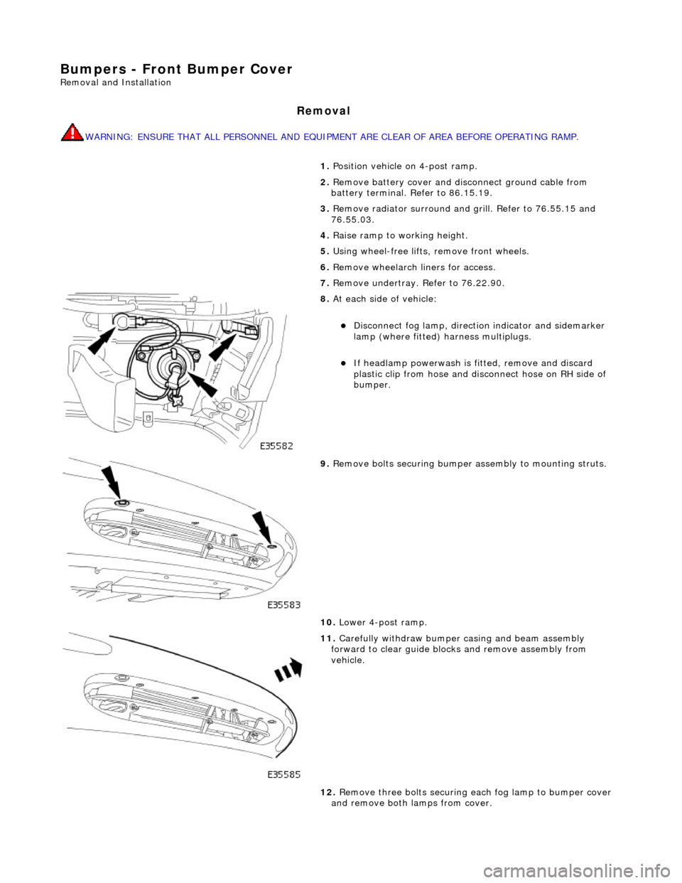
Bumpers - Front Bumper Cover
Removal and Installation
Removal
WARNING: ENSURE THAT ALL PERSONNEL AND EQUIPMENT ARE CLEAR OF AREA BEFORE OPERATING RAMP.
1. Position vehicle on 4-post ramp.
2. Remove battery cover and disc onnect ground cable from
battery terminal. Refer to 86.15.19.
3. Remove radiator surround and grill. Refer to 76.55.15 and
76.55.03.
4. Raise ramp to working height.
5. Using wheel-free lifts, remove front wheels.
6. Remove wheelarch liners for access.
7. Remove undertray. Refer to 76.22.90.
8. At each side of vehicle:
Disconnect fog lamp, directio n indicator and sidemarker
lamp (where fitted) harness multiplugs.
If headlamp powerwash is fitted, remove and discard
plastic clip from hose and disconnect hose on RH side of
bumper.
9. Remove bolts securing bumper assembly to mounting struts.
10. Lower 4-post ramp.
11. Carefully withdraw bumper casing and beam assembly
forward to clear guide blocks and remove assembly from
vehicle.
12. Remove three bolts securing each fog lamp to bumper cover
and remove both lamps from cover.
Page 2352 of 2490
16.
Install wheelarch liners.
17. Install undertray. Refer to 76.22.90.
18. Lower 4-post ramp.
19. Install road wheels and lower wheel-free lifts.
20. Position number plate plinth on bumper and install securing
screws.
21. Install number plate.
22. Connect ground cable to batter y terminal and install battery
cover. Refer to 86.15.15.
Page 2360 of 2490
Safety Belt System - Safety Belt System
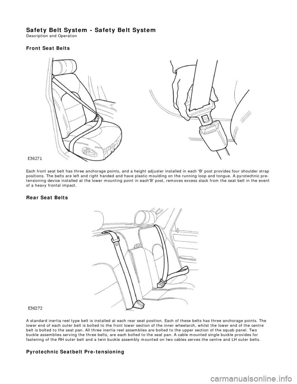
Description and Operation
Front Seat Belts
Each front seat belt has three anchorage points, and a height adjuster installed in each 'B' post provides four shoulder strap
positions. The belts are left and right ha nded and have plastic moulding on the r unning loop and tongue. A pyrotechnic pre-
tensioning device installed at the lower mounting point in each 'B' post, removes excess slack from the seat belt in the event
of a heavy frontal impact.
Rear Seat Belts
A standard inertia reel type belt is installed at each rear seat position. Each of these belts has three anchorage points. The
lower end of each outer belt is bolted to the front lower section of the inner wheelarch, whilst the lower end of the centre
belt is bolted to the seat pan. All thr ee inertia reel assemblies are bolted to the upper section of the squab panel. Two
buckle assemblies serving the three belts, are each bolted to the seat pan. A cable mounted single buckle provides for
fastening of the RH outer belt and a twin buckle assembly mounted on two cables serves the centre and LH outer belts.
Pyrotechnic Seatbelt Pre-tensioning