Page 2387 of 2490
Key to Plan
Standard Wheelbase Body Dimensions- Side View
KeyLocation
1Front face body-bumper strut/mounting point
2Rearmost hole, vee-mount to crush tube
3Front Master Datum Plan, centre li ne of front crossmember rear mount ing at main floor RH longitudinal
4Rearmost hole, transmission mounting at main floor RH longitudinal
5Handbrake rear lever bracket fixings
6Rear Master Datum Plan, rear longitudinal
7Tapped boss, rear suspension 'A' frame mounting bush
8Rear suspension spring-pan damper mounting
9Rear suspension differential strut mounting
10Rear face body-bumper strut/mounting point
11Driveshaft centre bearing mounting
Page 2388 of 2490
Key to SideView
Long Wheelbase Body Dimensions-Plan
KeyLocation
1Front face body-bumper strut/mounting point
2Front Master Datum Vertical, centre line of front crossmember rear mounting
3Transmission mountings at the main floor longitudinal
4Handbrake rear lever bracket fixings
5Rear Master Datum Vertical,, rear longitudinal
6Tapped boss, rear suspensi on 'A' frame mounting bush
7Rear suspension spring-pan damper mounting
8Rear suspension differential strut mounting
9Rear face body-bumper strut/mounting point
10Wheel centre to bumper cover face
11Wheelbase
12Wheel Centre to Bumper Cover Face
13Driveshaft centre bearing mounting
Page 2389 of 2490
Key to Plan
Long Wheelbase Body Dimensions- Side View
KeyLocation
1Front face body-bumper strut/mounting point
2Rearmost hole, vee-mount to crush tube
3Front Master Datum Plan, centre line of front crossmember rear mount ing at main floor RH longitudinal
4Rearmost hole, transmission mounting at main floor RH longitudinal
5Handbrake rear lever bracket fixings
6Rear Master Datum Plan, rear longitudinal
7Tapped boss, rear suspension 'A' frame mounting bush
8Rear suspension spring-pan damper mounting
9Rear suspension differential strut mounting
10Rear face body-bumper strut/mounting point
11Driveshaft centre bearing mounting
Page 2390 of 2490
Key to SideView
KeyLocation
1Front face body-bumper strut/mounting point
2Front Master Datum Vertical, centre line of front crossmember rear mounting
3Transmission mountings at the main floor longitudinal
4Handbrake rear lever bracket fixings
5Rear Master Datum Vertical,, rear longitudinal
6Tapped boss, rear suspensi on 'A' frame mounting bush
7Rear suspension spring-pan damper mounting
8Rear suspension differential strut mounting
9Rear face body-bumper strut/mounting point
10Wheel centre to bumper cover face
11Wheelbase
12Wheel Centre to Bumper Cover Face
13Driveshaft centre bearing mounting
Page 2416 of 2490

Replacement bumper cover assemblies includer side armatures, which should be removed from discarded bumper
assemblies and rout ed for recycling.
BODY SIDE MOULDINGS
Description
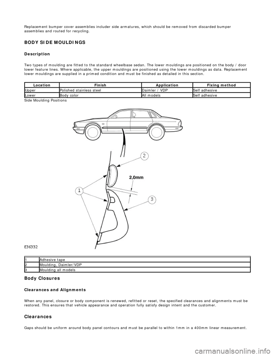
Two types of moulding are fitted to the standard wheelbase sedan. The lower mouldings are positioned on the body / door
lower feature lines. Where applicable, the upper mouldings are positioned using the lower mouldings as data. Replacement
lower mouldings are supplied in a primed condition and must be finished as detailed in this section.
Side Moulding Positions
Body Closures
Clearances and Alignments
When any panel, closure or body component is renewed, refitted or reset, the specified clearances and alignments must be
restored. This ensures that vehicle appearance and operation fully satisfy design intent and the customer.
Clearances
Gaps should be uniform around body panel contours and must be parallel to within 1mm in a 400mm linear measurement.
LocationFinishApplicationFixing method
UpperPolished stainless steelDaimler / VDPSelf adhesive
LowerBody colorAll modelsSelf adhesive
1Adhesive tape
2Moulding, Daimler/VDP
3Moulding all models
Page 2422 of 2490
8. Remove generator front cooling duct.
Remove bolt.
Move duct rearwards to rele ase tang from undertray.
Release front duct from rear vertical duct.
9. Remove scrivets or screws se curing undertray to bumper
cover. Discard scrivets.
10. Remove and discard tiestrap securing undertray to body
brace.
11. At each side of vehicle, remo ve and discard scrivet securing undertray to wheelarch liner.
12. Remove undertray from vehicle.
13. Remove both front road wheels. Refer to Section 100-02.
14. Remove both front road springs. Refer to 60. 20.02.
15. Disconnect wheel speed sensor harness connectors.
Page 2423 of 2490
1. Sever and discard tiestraps securing front wheel
speed sensor harness to upper wishbone.
2. Disconnect harness connector from sensor.
Repeat procedure to disconnect opposite side wheel speed
sensor harness.
16. CAUTION: Do not suspend caliper from brake hose as
this will damage the hose.
Remove brake calipers from carriers.
1. Remove caliper spring clip.
2. Remove guide pin dust caps.
3. Slacken and withdraw guide pins.
4. Remove caliper from carrier and tie to suspension mounting bracket.
Repeat procedure to remove opposite side front brake
caliper.
17. Remove filler cap from power steering fluid reservoir.
18. Disconnect steering rack transducer harness front connector.
Release harness connector from body retaining clip.
Disconnect connector.
19. Sever and discard tiestrap secu ring return pipe, harness (RHD
only) and rubber support to steering rack.
Page 2436 of 2490
30. Connect steering harness.
Route harness connector to body front location.
Connect steering ha rness connector.
Install connector in body retaining clip.
31. Connect wheel speed sensor harness.
1. Connect wheel speed sensor harness to sensor.
2. Using new tiestraps secure wheel speed sensor harness to upper wishbone.
Repeat procedure to connect opposite side wheel speed
sensor.
32. Install brake calipers.
1. Install caliper on carrier.
2. Install guide pins.
3. Install guide pin dust caps.
4. Install caliper spring clip.
Repeat procedure to install opposite side front brake
caliper.
33. Install both front road sp rings. Refer to 60. 20.02.
34. Using screws or new scrivets , secure undertray to front
bumper cover.