Page 2279 of 2490

Installation
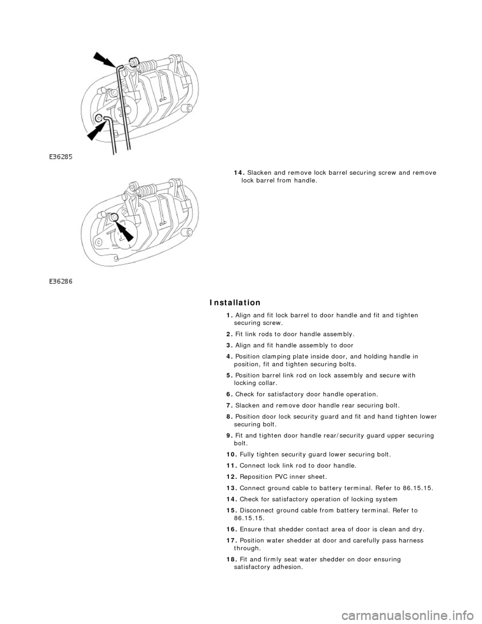
14. Slacken and remove lock barre l securing screw and remove
lock barrel from handle.
1. Align and fit lock barrel to door handle and fit and tighten
securing screw.
2. Fit link rods to door handle assembly.
3. Align and fit handle assembly to door
4. Position clamping plate inside door, and holding handle in
position, fit and tighten securing bolts.
5. Position barrel link rod on lock assembly and secure with
locking collar.
6. Check for satisfactory door handle operation.
7. Slacken and remove door handle rear securing bolt.
8. Position door lock security guard and fit and hand tighten lower
securing bolt.
9. Fit and tighten door handle rear /security guard upper securing
bolt.
10. Fully tighten security guard lower securing bolt.
11. Connect lock link rod to door handle.
12. Reposition PVC inner sheet.
13. Connect ground cable to battery terminal. Refer to 86.15.15.
14. Check for satisfactory operation of locking system
15. Disconnect ground cable from battery terminal. Refer to
86.15.15.
16. Ensure that shedder contact area of door is clean and dry.
17. Position water shedder at door and carefully pass harness
through.
18. Fit and firmly seat water shedder on door ensuring
satisfactory adhesion.
Page 2283 of 2490

Installation
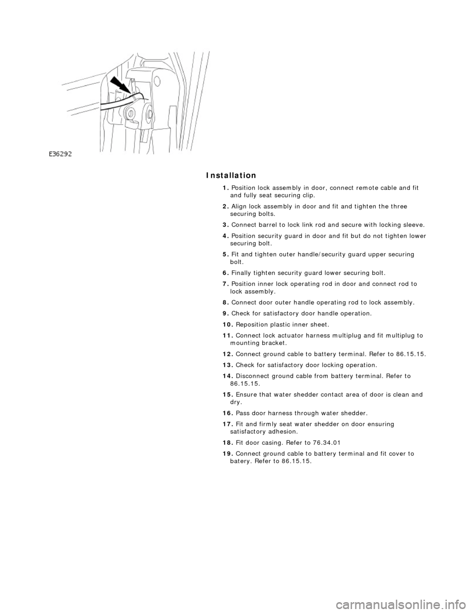
1. Position lock assembly in door, connect remote cable and fit
and fully seat securing clip.
2. Align lock assembly in door and fit and tighten the three
securing bolts.
3. Connect barrel to lock link rod and secure with locking sleeve.
4. Position security guard in door and fit but do not tighten lower
securing bolt.
5. Fit and tighten outer handle/security guard upper securing
bolt.
6. Finally tighten security guard lower securing bolt.
7. Position inner lock operating ro d in door and connect rod to
lock assembly.
8. Connect door outer handle operating rod to lock assembly.
9. Check for satisfactory door handle operation.
10. Reposition plastic inner sheet.
11. Connect lock actuator harness multiplug and fit multiplug to
mounting bracket.
12. Connect ground cable to battery terminal. Refer to 86.15.15.
13. Check for satisfactory door locking operation.
14. Disconnect ground cable from battery terminal. Refer to
86.15.15.
15. Ensure that water shedder contact area of door is clean and
dry.
16. Pass door harness through water shedder.
17. Fit and firmly seat water shedder on door ensuring
satisfactory adhesion.
18. Fit door casing. Refer to 76.34.01
19. Connect ground cable to battery terminal and fit cover to
batery. Refer to 86.15.15.
Page 2284 of 2490
Handles, Locks, Latches and Entry Systems - Glove Compartment Lid
Handle
Removal and Installation
Removal
Installation
1.
Remove glovebox lid. Refer to 76.52.02.
2. Remove the glove box ha ndle and lock barrel.
1. Holding the handle in the open position, remove it from the mounting bracket by carefully prising the RH
support outwards.
2. Remove the handle return spring.
3. Releasing the retaining tangs, remove the lock barrel.
1. Install glove box handle and lock barrel to lid.
1. Install handle return spring ensuring that it engages in the lid mounting slot.
2. Position lock rods inwards and Install and fully seat handle in right-hand mounting bracket.
3. Install lock barrel to lid.
2. Install glovebox lid. Refer to 76.52.02.
Page 2286 of 2490
6.
Fit bias spring to operating arm ensuring it is fully seated and
tensioned, with ends positioned each side of pillar.
7. Fit operating arm and bias spring assembly to barrel and
secure with 'C' clip.
8. Fit lock barrel assembly to housing.
9. Position lock assembly in handle and fit and tighten securing
screw.
10. Fit key and check lock function.
11. Remove key from lock.
12. Fit handle and lock assembly to glovebox lid.. Refer to 76.52
08.
Page 2288 of 2490
Installation
7. Disconnect lock barrel link rod.
8. Disconnect lock motor link rod.
9. Withdraw lock assembly from trunk , release trunk open
switch retaining tang and remove switch from lock assembly.
1. Fit and fully seat trunk open switch to lock assembly.
2. Position lock assembly in trunk and connect lock barrel and
Page 2289 of 2490
lock motor link rods.
3.
Fit and tighten lock assembly securing bolt.
4. Connect lock switch multiplug and install in mounting clip.
5. Reposition trunk lid liner and secure with new fasteners.
6. Position lock finisher and fi t and tighten securing bolts.
7. Fit and fully seat covers over finisher securing bolts.
8. Fit trunk light. Refer to 86.45.16.
Page 2291 of 2490
Installation
8.
Remove motor and bracket assembly from trunk lid
9. Slacken and remove bolts securing lock motor to mounting
bracket and separate motor from bracket.
1. Position motor on mounting bracket and fit and tighten
securing bolts.
2. Position motor/bracket assembly in trunk lid and connect lock
link rod and harness multiplug.
3. Finally position motor/bracket as sembly in trunk lid and fit and
tighten securing bolts.
4. Position trunk lid liner and fit and fully seat new fasteners.
5. Position finisher over trunk lock.
6. Fit and tighten finisher securing bolts and fit bolt covers..
7. Connect ground cable to battery terminal and fit battery cover.
Refer to 86.15.15.
Page 2295 of 2490
Installation
7. Disconnect lock barrel link rod.
8. Disconnect lock motor link rod.
9. Withdraw lock assembly from trunk , release trunk open
switch retaining tang and remove switch from lock assembly.
1. Install and fully seat trunk open switch to lock assembly.
2. Position lock assembly in trunk and connect lock barrel and