Page 2219 of 2490

Instrument Panel and Console - Instrument Panel and Instrument Panel
Console
Description and Operation
Fascia
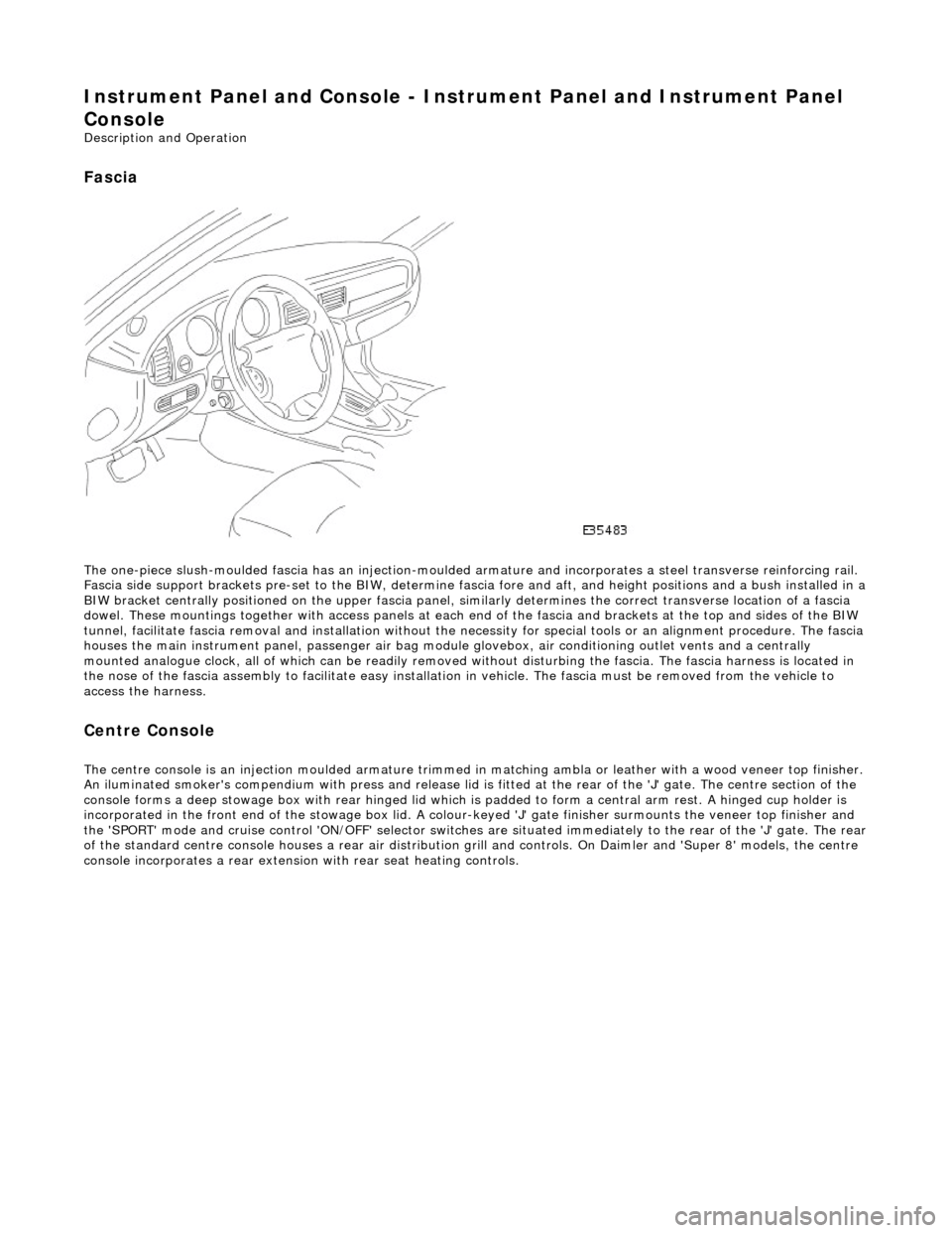
The one-piece slush-moulded fascia has an injection-moulded ar mature and incorporates a steel transverse reinforcing rail.
Fascia side support brackets pre-set to th e BIW, determine fascia fore and aft, and height position s and a bush installed in a
BIW bracket centrally positioned on the upper fascia panel, similarly determines the correct transverse location of a fascia
dowel. These mountings together with access panels at each en d of the fascia and brackets at the top and sides of the BIW
tunnel, facilitate fascia removal and instal lation without the necessity for special tools or an alignment procedure. The fasci a
houses the main instrument panel, pass enger air bag module glovebox, air conditioning outlet vents and a centrally
mounted analogue clock, all of which can be readily removed wi thout disturbing the fascia. The fascia harness is located in
the nose of the fascia assembly to facilitate easy installati on in vehicle. The fascia must be removed from the vehicle to
access the harness.
Centre Console
The centre console is an injection moulded armature trimmed in matching ambla or leather with a wood veneer top finisher.
An iluminated smoker's compendium with pr ess and release lid is fitted at the rear of the 'J' gate. The centre section of the
console forms a deep stowage box with rear hinged lid which is padded to form a central arm rest. A hinged cup holder is
incorporated in the front end of the stowage box lid. A colour-keyed 'J' gate finisher surmounts the veneer top finisher and
the 'SPORT' mode and cruise control 'ON/OFF' selector switches are situated immediately to the rear of the 'J' gate. The rear
of the standard centre console houses a re ar air distribution grill and controls. On Daimler and 'Super 8' models, the centre
console incorporates a rear extensio n with rear seat heating controls.
Page 2220 of 2490

Instrument Panel and Console - Audio Unit Housing
Removal and Installation
Removal
Installation
1.
Remove centre console veneer pa nel. Refer to operations in
this section.
2. Withdraw radio from console for access, disconnect multiplugs
and aerial lead and remo ve radio from vehicle.
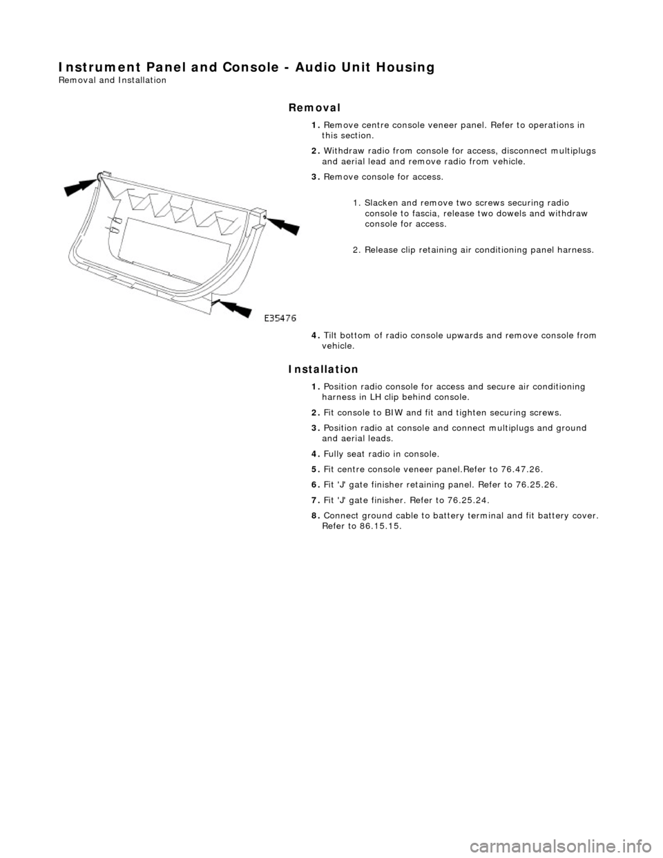
3. Remove console for access.
1. Slacken and remove tw o screws securing radio
console to fascia, release two dowels and withdraw
console for access.
2. Release clip retaining air conditioning panel harness.
4. Tilt bottom of radio console upwards and remove console from
vehicle.
1. Position radio console for access and secure air conditioning
harness in LH clip behind console.
2. Fit console to BIW and fit an d tighten securing screws.
3. Position radio at console and connect multiplugs and ground
and aerial leads.
4. Fully seat radio in console.
5. Fit centre console veneer panel.Refer to 76.47.26.
6. Fit 'J' gate finisher retain ing panel. Refer to 76.25.26.
7. Fit 'J' gate finisher . Refer to 76.25.24.
8. Connect ground cable to battery terminal and fit battery cover.
Refer to 86.15.15.
Page 2222 of 2490
2.
Position air conditioning panel and console at centre console
and connect multiplugs.
3. Fully seat air conditioning pa nel and console on BIW bracket
and fit and tighten securing screw.
4. Fit radio and console. Refer to operations in this section.
5. Fit centre console veneer panel. Refer to operations in this
section.
6. Fit 'J' gate surround. Refer to operations in this section.
7. Fit 'J' gate finisher. Refer to operations in this section.
8. Connect ground cable to battery terminal and fit battery cover.
Refer to 86.15.15.
9. Return 'J' gate selector to position 'P'.
Page 2226 of 2490
multiplug.
11.
Where applicable, install console rear extension. Refer to
76.25.05.
12. Fit and firmly seat air distribu tion control grill to rear of
console.
13. Move 'J' gate selector to 'P'.
14. Connect ground cable to batt ery terminal and fit battery
cover. refer to 86.15.15.
Page 2227 of 2490

Instrument Panel and Console - Floor Console Ashtray
Removal and Installation
Removal
Installation
1.
Remove battery cover and disc onnect ground cable from
battery terminal. Refer to 86.15.19.
2. Remove center console for access . Refer to operations in this
section.
3. Open ashtray lid and remove cigar lighter.
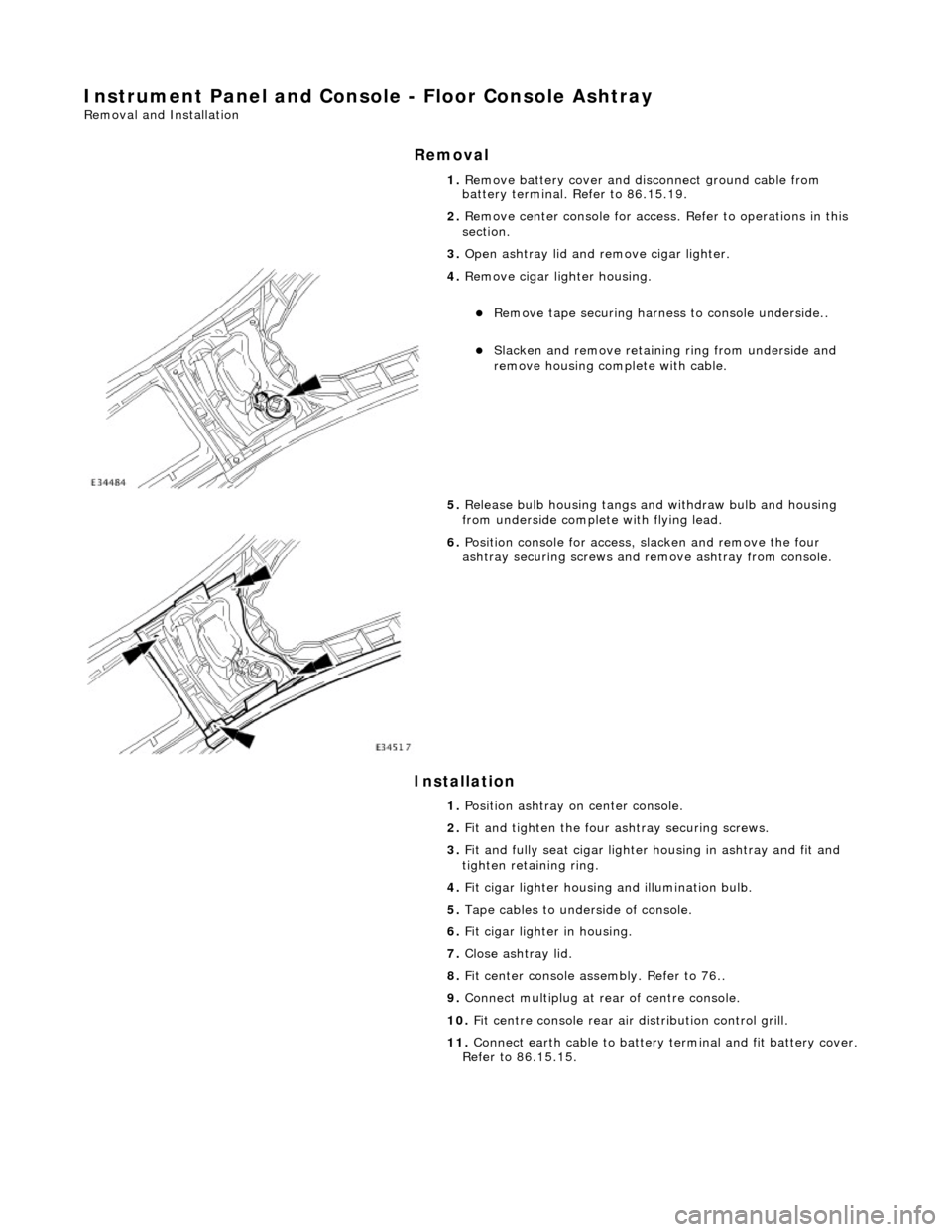
4. Remove cigar lighter housing.
Remove tape securing harnes s to console underside..
Slacken and remove retaining ring from underside and
remove housing complete with cable.
5. Release bulb housing tangs and withdraw bulb and housing
from underside complete with flying lead.
6. Position console for access, slacken and remove the four
ashtray securing screws and remove ashtray from console.
1. Position ashtray on center console.
2. Fit and tighten the four ashtray securing screws.
3. Fit and fully seat cigar lighter housing in ashtray and fit and
tighten retaining ring.
4. Fit cigar lighter housing and illumination bulb.
5. Tape cables to underside of console.
6. Fit cigar lighter in housing.
7. Close ashtray lid.
8. Fit center console assembly. Refer to 76..
9. Connect multiplug at rear of centre console.
10. Fit centre console rear air distribution control grill.
11. Connect earth cable to battery te rminal and fit battery cover.
Refer to 86.15.15.
Page 2228 of 2490
Instrument Panel and Console - Floor Console Extension
Removal and Installation
Removal
Installation
1. Using a thin plastic lever at th e edge and exercising care to
avoid damage to surface, remove veneer panel from rear
extension.
2. Slacken and remove the two rear extension securing screws.
3. Remove rear seat heater switches.
Position rear extension for access and slacken and remove
screw retaining switches.
Mark both harness multip lugs to ensure correct
reconnection and disconnect multiplugs.
4. Remove heater switches.
1. Position rear seat heater switches in rear extension.
2. Noting identity of multiplugs as marked during removal, connect
harness multiplugs to heater switches.
3. Position switches in console extension and fit and tighten
retaining screw.
4. Position and fully seat extension at rear of console and fit and
tighten securing screws.
5. Carefully fit veneer panel to rear extension.
Page 2230 of 2490
Installation
1. Position veneer panel on consol e, ensuring that front tongue
locates correctly in console upper slot.
2. Fit and fully seat new bush es in retaining panel.
3. Position retaining panel complete with SPORT mode and cruise
control ON/OFF switches for ac cess and connect multiplugs.
4. fully seat retaining panel and fi t and tighten securing nuts and
screws.
5. Fit 'J' gate surround finisher. Refer to 76.25.24.
6. Move gear selector to position P.
7. Connect cable to battery earth te rminal and fit battery cover.
Refer to Section 86.15.15.
Page 2231 of 2490
In
strument Panel and Console - Floor Console Finish Panel Bracket
Rem
oval and Installation
Remov
al
Installation
1.
Remove 'J' gate finisher. Refer to 76.25.24.
2.
Slacken and remove the two front nuts and two rear screws
securing the retaining panel.
3.
Position retaining panel for access, disconnect SPORT mode and
cruise control ON/OFF switch multiplugs and remove retaining
panel complete with switches.
4. Remove switches from retaining panel.
5.
Remove and discard bushes from retaining panel.
1. Fit and fully seat new bushes in retaining panel.
2. Fit and fully seat SPORT mode and cruise control ON/OFF
switches in retaining panel.
3. Position retaining panel for access and connect SPORT mode and
cruise control ON/OFF switch multiplugs.
4. Fully seat retaining panel and fit and tighten securing nuts and
screws.
5. Fit 'J' gate surround finisher. Refer to 76.25.24.